Z9F-TPMS203OTRTire Pressure Monitoring System
SHANGHAI BAOLONG AUTOMOTIVE CORPORATION
Click to zoom
Application Details
- Equipment Class
- DSC - Part 15 Security/Remote Control Transmitter
- Date of Grant
- Apr 14, 2014
- Application Purpose
- Original Equipment
- Date of Application
- Apr 14, 2014
- Equipment Note
- Tire Pressure Monitoring System
- Frequency Range
- 433.92000000 - 433.92000000
- Country
- China
Documents & Files
Document Text
Text extracted from the exhibit documents filed with the FCC. Open a document above to read the original.
Users Manual
1 TABLE OF CONTENTS 1.1 INTRODUCTION ................................................................................................................................2 1.2 WORKING MODE ..............................................................................................................................2 1.2.1 NORMAL PRESSURE INSPECTING............................................................................................................. 2 1.2.2 LOW PRESSURE WARNING MODE............................................................................................................. 2 1.2.3 AIR LEAKAGE WARNING MODE........................................................................................................ 2 1.2.4 STATIONARY WORKING MODE········································································································2 1.2.5 HIGH TEMPERATURE WARNING MODE··························································································3 1.2.6 LOW FREQUENCE AWAKING MODE································································································3 1.3 INSTALLATION TRANSMITTER ................................................................................................................ 3 1.3.1 INSTALLATION TRANSMITTER...............................................................................................................................3 1.3.2 INSTALLATION ID MODULE.................................................................................................................................... 8 1.3.3 REMOVING TRANSMITTER.................................................................................................................................... 8 1.4 PARAMETERS OF THE PRODUCTS ...............................................................................................8 1.5 FCC's AUNTHENTICATION ANNOUNCEMENT...............................................................................9 1.6 EUROPEAN REGULATIONS ANNOUNCEMENTS ..........................................................................9 1.7 CE DIRECTIVE ANNOUMCEMENT ..................................................................................................9 2 1.1 INTRODUCTION 1.1.1 Patchy Installation Method Magnetic Installation Method 1.2 WORKING MODE 1.2.1 NORMAL PRESSURE INSPECTING If the pressure and temperature of tire is normal(when the pressure is over 4bar and the temperature is below 80°C), the transmitter will send pressure and temperature data every 30 seconds. 1.2.2 LOW PRESSURE WARNING MODE If the pressure of tire is between 0.66 Bar and 4 Bar, the transmitter will send pressure data every 4 seconds including low pressure warning sign. 1.2.3 AIR LEAKAGE WARNING MODE Transmitter: Mounted inside the tire on the centre of wheel using magnet or patch to continuously monitor tire’s pressure and temperature every 10-second and transmit data via RF to the integrated display at 30-second intervals when tires are normal or immediately when the tires are abnormal. ID Module: ID module is an international patented innovative technology used to identify tire’s position without any activation tool or complicated operation. Each ID module has an exclusive transmitter with the same ID code. The ID module is mounted in the display and Trailer ID box to register transmitter’s ID code into the display that will recognize wheel positions as well as the baseline pressures for all tires. 3 If over 0.33 Bar / 4.78PSI pressure loss in 16 seconds: the sensor will send data with quick leakage icon immediately; If over 0.16bar/2.32PSI pressure loss in 8 seconds: the sensor will send data without quick leakage icon immediately. 1.2.4 STATIONARY WORKING MODE If the pressure is below 0.66Bar, the sensor will not send any data and enter into stationary working mode. 1.2.5 HIGH TEMPERATURE WARNING MODE If the temperature is over 80°C, the sensor will send temperature data with high temperature warning icon. 1.2.6 LOW FREQUENCE AWAKING MODE Use the handled tool to awake the sensor to find out its ID number, pressure and temperature data. 1.3 INSTALLATION TRANSMITTER • Before installation, make sure you identify each pair of transmitter and ID module. We have two installation methods: magnetic installation method and patchy installation method. For magnetic installation method, there is a pair of transmitters & ID modules along with two magnets packed in a small box, they have the same ID code. For patchy installation method, there is also a pair of transmitters & ID modules along with a patch packed in a small box, they have the same ID code. For example: DF102027. Install the transmitter in the wheel with magnets or patch. Then install the ID modules in the corresponding position of display and trailer ID box. 1.3.1 Installation Transmitter 1.3.1.1 Remove the wheel from the vehicle and then remove the tire. Clean the area where the transmitter is to be installed. 1.3.1.2 Installation the transmitter 4 1> Patchy installation method Carefully cut the plastic cover without cutting the patch 5 Once the sensor is correctly in place with the mounting holes lined up with the mounting bracket, replace the screws to secure the sensor to the mounti: The final installation is shown in the following picture: Mounting hole and Mounting screw 6 2> Magnetic Installation Method Clean the magnets and the bottom of the sensor: Insert the two magnets into the frame of the sensor’s bottom: Take the rubber cover of the tire and then attach the sensor (shown as in the following picture) to the rim: 7 NOTE: The transmitter must be positioned in the lowest spot possible and installed beside the tire valve in order to know its approximate location after the tire has been mounted. NOTE: When fixing the transmitter on the rim, make sure the section of steel strap installed through the transmitter is complete NOT TOOTHED. 1.3.1.3 Mount the tire on the rim, inflate tire to standard …
Text truncated - open the document above for the full version.
Cover Letter(s)
SHANGHAI BAOLONG AUTOMOTIVE CORPORATION 5500, Shenzhuan Rd, Songjiang District, Shanghai 201619, China. Long Term Confidentiality Request Letter April 02, 2014 MET Laboratories, Inc. 914 West Patapsco Avenue Baltimore, MD 21230 RE: CONFIDENTIALITY REQUEST FOR (Tyre Pressure Monitoring System, Model: TPMS203, FCC ID: Z9F -TPMS203OTR To Whom It May Concern: This letter serves as an official request for confidentiality under sections 0.457 and 0.459 of CFR 47. We have requested that the (Schematics, Operational Description, Block Diagram) required to be submitted with this application be permanently withheld from public review. The above documents are company proprietary information that could never get into the possession of your competition). Please contact me if there is any information you may need. Sincerely,
ID Label/Location Info
FCC ID Label Location
ID Label/Location Info
FCC ID: Z9F-TPMS203OTR IC: 11852A-TPMS203OTR Model: TPMS203
Test Report
ISO/IEC17025 Accredited Lab. Report No: FCC/IC1401044 File reference No: 2014-04-10 Applicant: SHANGHAI BAOLONG AUTOMOTIVE CORPORATION Product: Tyre Pressure Monitoring System Model No: TPMS203 Trademark: Valor, Digitire Test Standards: FCC Part 15 Subpart C, Paragraph 15.231 and RSS-210 Issue 8 Test result: It is herewith confirmed and found to comply with the requirements set up by ANSI C63.4&FCC Part 15 Subpart C, Paragraph 15.231 and RSS-210 Issue 8 regulations for the evaluation of electromagnetic compatibility Approved By Jack Chung Manager Dated: April 10, 2014 Results appearing herein relate only to the sample tested The technical reports is issued errors and omissions exempt and is subject to withdrawal at SHENZHEN TIMEWAY TECHNOLOGY CONSULTING CO LTD 5/F,Block 4, Anhua Industrial Zone.,No.8 TaiRan Rd.CheGongMiao,FuTian District, Shenzhen,CHINA. Tel (755) 83448688 Fax (755) 83442996 Report No: FCC/IC1401044 Page 2 of 30 Date: 2014-04-10 The report refers only to the sample tested and does not apply to the bulk. This report is issued in confidence to the client and it will be strictly treated as such by the Shenzhen Timeway Technology Consulting Co .,Ltd. It may not be reproduced rather in its entirety or in part and it may not be used for adverting. The client to whom the report is issued may, however, show or send it . or a certified copy there of prepared by the Shenzhen Timeway Technology Consulting co .,Ltd to his customer. Supplier or others persons directly concerned. Shenzhen Timeway Technology Consulting co .,Ltd will not, without the consent of the client enter into any discussion of correspondence with any third party concerning the contents of the report. In the event of the improper use of the report. The Shenzhen Timeway Technology Consulting co .,Ltd reserves the rights to withdraw it and to adopt any other remedies which may be appropriate. Special Statement: The testing quality ability of our laboratory meet with "Quality Law of People's Republic of China" Clause 19. The testing quality system of our laboratory meets with ISO/IEC-17025 requirements, which is approved by CNAS. This approval result is accepted by MRA of APLAC. Our test facility is recognized, certified, or accredited by the following organizations: CNAS-LAB Code: L2292 The EMC Laboratory has been assessed and in compliance with CNAS-CL01 accreditation criteria for testing Laboratories (identical to ISO/IEC 17025:1999 General Requirements) for the Competence of testing Laboratories. FCC-Registration No.: 899988 The EMC Laboratory has been registered and fully described in a report filed with the (FCC) Federal Communications commission. The acceptance letter from the FCC is maintained in our files. Registration No.:899988. IC- Registration No.: IC5205A-02 The EMC Laboratory has been registered and fully described in a report filed with the (IC) Industry Canada. The acceptance letter from the IC is maintained in our files. Registration No.: IC 5205A-02. Report No: FCC/IC1401044 Page 3 of 30 Date: 2014-04-10 The report refers only to the sample tested and does not apply to the bulk. This report is issued in confidence to the client and it will be strictly treated as such by the Shenzhen Timeway Technology Consulting Co .,Ltd. It may not be reproduced rather in its entirety or in part and it may not be used for adverting. The client to whom the report is issued may, however, show or send it . or a certified copy there of prepared by the Shenzhen Timeway Technology Consulting co .,Ltd to his customer. Supplier or others persons directly concerned. Shenzhen Timeway Technology Consulting co .,Ltd will not, without the consent of the client enter into any discussion of correspondence with any third party concerning the contents of the report. In the event of the improper use of the report. The Shenzhen Timeway Technology Consulting co .,Ltd reserves the rights to withdraw it and to adopt any other remedies which may be appropriate. Test Report Conclusion Content 1.0 General Details ................................................................................................ 4 1.1 Test Lab Details................................................................................................ 4 1.2 Applicant Details.............................................................................................. 4 1.3 Description of EUT .......................................................................................... 4 1.4 Submitted Sample............................................................................................. 4 1.5 Test Duration.................................................................................................... 5 1.6 Test Uncertainty.................................................................................................5 1.7 Test By.......................................................................................................... 5 2.0 List of Measurement Equipment......................................................................... 5 3.0 Technical Details............................................................................................. 7 3.1 Summary of Test Results..................................................................................... 7 3.2 Test Standards.................................................................................................. 7 4.0 EUT Modification............................................................................................. 7 5.0 Power Line Conducted Emission Test...................................................................... 7 5.1 Schematics of the Test........................................................................................ 7 5.2 Test Method and Test Procedure............................................................................ 7 5.3 Configuration of the EUT.................................................................................... 7 5.4 …
Text truncated - open the document above for the full version.
Test Setup Photos
Radiated emission test view
Contact Information
Applicant
Changwu Xu
Test Firm
Shenzhen Timeway Testing LaboratoriesJack Chung
Technical Specifications
| # | Rule Parts | Frequency Range | Power Output |
|---|---|---|---|
| 1 | 15.231 | 433.92 MHz - 433.92 MHz | - |
Other Applications from SHANGHAI BAOLONG AUTOMOTIVE CORPORATION

Z9F-TPMSC
Sep 08, 2015TPMS Sensor
Equipment Class
DSC - Part 15 Security/Remote Control Transmitter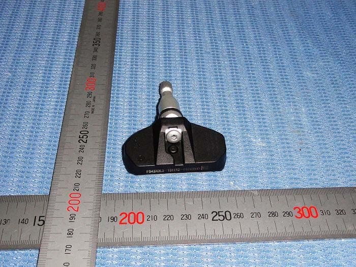
Z9F-201FS43X
Apr 03, 2014Tire Pressure Monitoring System
Equipment Class
DSC - Part 15 Security/Remote Control Transmitter
Z9FTPMS201-JS18G1
Nov 13, 2011Tyre Pressure Monitoring System
Equipment Class
CYY - Communications Receiver used w/Pt 15 Transmitter