Z9O-FAS1505Hub
Ecolab Inc.
Click to zoom
Application Details
- Equipment Class
- DSR - Part 15 Remote Control/Security Device Transceiver
- Date of Grant
- Jun 20, 2012
- Application Purpose
- Original Equipment
- Date of Application
- Jun 19, 2012
- Equipment Note
- Hub
- Frequency Range
- 433.90000000 - 433.90000000
- Company
- Ecolab Inc.
- Country
- United States
Documents & Files
Document Text
Text extracted from the exhibit documents filed with the FCC. Open a document above to read the original.
Users Manual
Bentley WiNET Hub User Guide FAS1505 DOC1037 Revision 0 Document Title UltraClenz, LLC Page 2 Table of Contents Revision History ......................................................................................................................................................... 3 Box Contents ............................................................................................................................................................. 4 Overview .................................................................................................................................................................... 4 Installing the Hub ....................................................................................................................................................... 5 Step 1 – Positioning the Chassis ........................................................................................................................... 5 Step 2 – Drilling the Holes ..................................................................................................................................... 5 Step 3 – Placing the Anchors ................................................................................................................................. 5 Step 4 – Mount the Tag to the Wall ....................................................................................................................... 5 Connecting the Hub to the Power Supply ................................................................................................................. 5 Step 1 – Inserting the Screwdriver ......................................................................................................................... 5 Step 2 – Inserting the Power Supply Wires ........................................................................................................... 6 Note: Please ensure proper polarity before plugging the power supply into an electrical outlet. ............................. 6 Configuring the Hub ................................................................................................................................................... 6 Maintenance of the Hub ............................................................................................................................................ 6 Cleaning ................................................................................................................................................................. 6 Certification and Safety Approvals ............................................................................................................................ 7 FCC ........................................................................................................................................................................ 7 Regulations ............................................................................................................................................................ 7 Warranty .................................................................................................................................................................... 8 Document Title UltraClenz, LLC Page 3 Revision History Revision Date By Description 0 01/25/11 MJB Initial Release D B O T t Document Ti Box Conte 1 1 2 1 Overview The FASxxxx ransmissions tle nts WiNET Hu Power Sup Screws an User’s Gui x WiNet Hub, s from the WiN ub (with Anten pply nd Anchors ide when used Net Tag to the nna) as a compo n e WiNET Gat Figure 1. – Wi Page 4 nent of the W eway (FASxx WiNET Network WiNET wireles xxx) (see Figu Topology ss monitoring ure 1). Ultra C g solution, re Clenz, LLC lays radio Document Title UltraClenz, LLC Page 5 Installing the Hub This procedure will require a small hammer, drill, drill bits, level and a screw driver. Step 1 – Positioning the Chassis Place the leveled WiNet Hub on the mounting location to transfer the drill centers. Step 2 – Drilling the Holes Drill 2 holes with the proper bit. Use standard bits for dry wall and masonry bits for tile applications. Step 3 – Placing the Anchors Gently tap the anchors in place using a hammer. Step 4 – Mount the Tag to the Wall Screw the WiNet Hub tightly to the wall. Connecting the Hub to the Power Supply This procedure will require a small flat-tip screwdriver. Step 1 – Inserting the Screwdriver Insert a small flat-tip screwdriver into the rectangular slot of the power connector marked + (positive) on the back of the hub (see Figure 2). With the tip of the small flat-tip screwdriver, depress the metal tab. Figure 2 Document Title UltraClenz, LLC Page 6 Step 2 – Inserting the Power Supply Wires With the small flat-tip screwdriver in place, insert the wire with the white stripe on it from the power supply (positive wire) (see Figure 3) into the circular opening directly beneath the rectangular slot until it stops and pull out the small flat-tip screwdriver to lock the wire in place. Give the positive wire a slight tug to insure that it is locked into place. Repeat the process for the rectangular slot of the power connector marked - (negative) on the back of the hub with the remaining wire. Note: Please ensure proper polarity before plugging the power supply into an electrical outlet. Configuring the Hub The WiNet Hub requires no configuration. Maintenance of the Hub Cleaning The exterior can be cleaned with a NON abrasive detergent and a NON abrasive damp (not wet) sponge or cloth. The Hub is splash resistant but not water proof. Figure 3 Document Title UltraClenz, LLC Page 7 Certification and Safety Approvals FCC This equipment has been tested and found to comply with the limits for a Class A digital device, pursuant to Part 15 of the FCC Rules. These limits are designed to provide reasonable protection against harmful interference when the equipment is operated in a commercial environment. This equipment generates uses and can…
Text truncated - open the document above for the full version.
Cover Letter(s)
From: Joe Dichoso [mailto:[email protected]] Sent: Tuesday , December 14, 2010 8:55 AM To: Shannon Krause; Raymond Laforge; David Galosky; Rashmi Doshi; Joe Dichoso; Jim Szeliga Cc: [email protected]; Brad Cole; Ric Ogden Subject: KDB 796294, RE: Equipment Approval RE: Ultraclenz Hello Charlie, We have agreement that hospital hand cleansing is a “safety” application under 15.231(a)3 but please note that it is not a “safety of life” alarm condition under 15.231(a)4. Also note that there are different transmission requirements under 15.231(a)3 and 15.231(a)4. Regards, Joe From: Charles C. Johnston [mailto:[email protected]] On Behalf Of Shannon Krause Sent: Thursday , December 09, 2010 1:38 PM To: Joe Dichoso Cc: [email protected]; 'Brad Cole'; 'Ric Ogden' Subject: Equipment Approval RE: Ultraclenz Mr. Dichoso, I appreciate your attention to this matter. For your reference the tracking number is 796294. The equipment, as part of a safety system, is designed for hospitals to prevent the spread of germs and toxics by hand contamination. Government statistics indicate that approximately 300,000 patients die each year by the spread of bacteria due to inadequate hand hygiene – failure to wash or sanitize hands while coming in contact with patients. As discussed: We are preparing for certification testing of a product that we have developed and want to verify that its operation would fall under Section 15.231, paragraph (a). The product is used to protect the health and safety of healthcare workers and patients by reducing the spread of communicable diseases through hand contact . The product monitors the activation of hand cleansing stations to ensure compliance with corporate or government hand sanitization policies. Background Highly infectious communicable diseases transmitted through direct contact, propagated from patient to patient by contact with healthcare workers who are unwitting carriers are a serious problem in healthcare facilities . In the most serious cases this bacteria can be flesh-eating and resistant to antibiotics. The most effective approach to managing this is killing the bacteria on carriers before it can be exposed to the patient. Facilities have instituted hand sanitization policies to respond to this, but its effectiveness today relies on voluntary compliance. Improved performance requires that compliance be verified and enforced on a REAL TIME basis. Description of Product Hand sanitization stations are typically located throughout a healthcare facility . The product we have developed would add a 433.92MHz radio to each station (Tag) so that it can communicate its activity. The Tag transmits a message to a receiving Hub when the hand sanitizer is manually activated. The messages received by the Hub control an alarm when the usage characteristics of the dispenser are not consistent with the policies of the organization, such as when a person enters a room but does not clean his hands within a certain period of time . Since the product is manually activated and controls an alarm based on that activation , we believe it satisfies the requirements described in 15.231 paragraph (a). The intended recipient of the message from the Tag may not be the nearest Hub, so the message may need to be relayed to another Hub one or more hops away. Therefore, each Hub needs to know what other devices are nearby with which it can communicate. To determine this, the system occasionally polls to determine what nodes are within range of the radio. Since this product protects patients from injury by protecting them from being exposed to potentially harmful bacteria, we believe it satisfies the requirement in paragraph 15.231(a)(3) as a product "used in security or safety applications." The operation of the product complies with the technical performance described in paragraphs 15.231(b) and 15.231(c). Again, I thank you for your attention to this matter and any help you may provide. If there are any questions please do not hesitate to contact me. Very Truly Yours, Charles Johnston CEO Ultraclenz, LLC Charles C. Johnston 1440 W. Indiantown Road Suite 350 Jupiter, FL 33458 Tel: 561-354-6300 Fax: 561-354-6301 Email: charlesj@ ventextech.com This communication may contain confidential and/or proprietary information. If you are not the intended recipient of this communication, please notify sender and delete this communication.
Cover Letter(s)
Subject: Response to Inquiry to FCC (Tracking Number 796294) FCC Home | Search | RSS | Updates | E-Filing | Initiatives | Consumers | Find People Office of Engineering and Technology Inquiry: We are preparing for certification testing of a product we have developed and want to verify that it would fall under Section 15.231, paragraph (a). The product is used to reduce the spread of communicable diseases by ensuring compliance with corporate or government hand sanitization policies. A radio in a hand sanitization dispenser (Tag) transmits a message to a receiving Hub when the hand sanitizer is manually activated. The messages received by the Hub control an alarm when the usage characteristics of the dispenser are not consistent with the policies of the organization, such as when a person enters a room but does not clean his hands within a certain period of time. Since the product is manually activated and controls an alarm based on that activation, it would seem to fall under 15.231 paragraph (a). Can you confirm our interpretation of the rules under this section? Regards, Brad Cole Response: From your description, it appears that the device you describe can be certified under rule part 15.231(a). If it is manually activated, it would have to have a switch to initiate the transmission. The rule part is such that data with a control signal is permitted. The device would also to have to comply with the radiated field strength as specified in 15.231 (b). The device must not transmit in the restricted band of operation as shown in rule part 15.205. Rule part 15.231 is as follows; § 15.231 Periodic operation in the band 40.66?40.70 MHz and above 70 MHz. (a) The provisions of this section are restricted to periodic operation within the band 40.66?40.70 MHz and above 70 MHz. Except as shown in paragraph (e) of this section, the intentional radiator is restricted to the transmission of a control signal such as those used with alarm systems, door openers, remote switches, etc. Continuous transmissions, voice, video and the radio control of toys are not permitted. Data is permitted to be sent with a control signal. The following conditions shall be met to comply with the provisions for this periodic operation: (1) A manually operated transmitter shall employ a switch that will automatically deactivate the transmitter within not more than 5 seconds of being released. (2) A transmitter activated automatically shall cease transmission within 5 seconds after activation. (3) Periodic transmissions at regular predetermined intervals are not permitted. However, polling or supervision transmissions, including data, to determine system integrity of transmitters used in security or safety applications are allowed if the total duration of transmissions does not exceed more than two seconds per hour for each transmitter. There is no limit on the number of individual transmissions, provided the total transmission time does not exceed two seconds per hour. (4) Intentional radiators which are employed for radio control purposes during emergencies involving fire, security, and safety of life, when activated to signal an alarm, may operate during the pendency of the alarm condition (5) Transmission of set-up information for security systems may exceed the transmission duration limits in paragraphs (a)(1) and (a)(2) of this section, provided such transmissions are under the control of a professional installer and do not exceed ten seconds after a manually operated switch is released or a transmitter is activated automatically. Such set-up information may include data. (b) In addition to the provisions of §15.205, the field strength of emissions from intentional radiators operated under this section shall not exceed the following: Fundamental frequency (MHz) Field strength of fundamental (microvolts/meter) Field strength of spurious emissions (microvolts/meter) 40.66?40.702,250225 70?1301,250125 130?174 1 1,250 to 3,750 1 125 to 375 174?2603,750375 260?470 1 3,750 to 12,500 1 375 to 1,250 Above 47012,5001,250 1 Linear interpolations. (1) The above field strength limits are specified at a distance of 3 meters. The tighter limits apply at the band edges. (2) Intentional radiators operating under the provisions of this section shall demonstrate compliance with the limits on the field strength of emissions, as shown in the above table, based on the average value of the measured emissions. As an alternative, compliance with the limits in the above table may be based on the use of measurement instrumentation with a CISPR quasi-peak detector. The specific method of measurement employed shall be specified in the application for equipment authorization. If average emission measurements are employed, the provisions in §15.35 for averaging pulsed emissions and for limiting peak emissions apply. Further, compliance with the provisions of §15.205 shall be demonstrated using the measurement instrumentation specified in that section. (3) The limits on the field strength of the spurious emissions in the above table are based on the fundamental frequency of the intentional radiator. Spurious emissions shall be attenuated to the average (or, alternatively, CISPR quasi-peak) limits shown in this table or to the general limits shown in §15.209, whichever limit permits a higher field strength. (c) The bandwidth of the emission shall be no wider than 0.25% of the center frequency for devices operating above 70 MHz and below 900 MHz. For devices operating above 900 MHz, the emission shall be no wider than 0.5% of the center frequency. Bandwidth is determined at the points 20 dB down from the modulated carrier. (d) For devices operating within the frequency band 40.66?40.70 MHz, the bandwidth of the emission shall be confined within the band edges and the frequency tolerance of the carrier shall be ±0.01%. This frequency tolerance shall be maintained for a temperature variation of ?20 degrees to +50 degrees C at normal supply voltage, and f…
Text truncated - open the document above for the full version.
External Photos
EK1442-3 UltraClenz LLC. External Pictures EK1442-3 UltraClenz LLC. External Pictures
Internal Photos
EK1442-3 UltraClenz LLC. Internal Photographs EK1442-3 UltraClenz LLC. Internal Photographs EK1442-3 UltraClenz LLC. Internal Photographs EK1442-3 UltraClenz LLC. Internal Photographs
Test Report
Curtis-Straus LLC is accredited by the American Association for Laboratory Accreditation for the specific scope of accreditation under Certificate Number 1627-01. This report may contain data which is not covered by the A2LA accreditation. ____________________________________________________________ Curtis-Straus LLC, a wholly owned subsidiary of BV CPS One Distribution Center Circle, #1 • •• • Littleton, MA • •• • TEL (978) 486-8880 • •• • FAX (978) 486-8828 page 1 of 15 Test Report Curtis-Straus LLC, a wholly owned subsidiary of BV CPS Report No EK1442-3 Client UltraClenz, LLC Address 1440 W. Indiantown Rd. Suite 350 Jupiter, FL 33458 Phone 561-840-8405 Items tested Hub Assembly FCC ID Z9O-FAS1505 FRN 0021282710 Equipment Type Security Device Transceiver Equipment Code DSR FCC Rule Parts 47 CFR 15.231(a) Test Dates November 8, 2010, December 20-22, 2010, April 12 and 30, 2012 Results As detailed within this report Prepared by Matthew Burman – Test Engineer Authorized by Mairaj Hussain – EMC Supervisor Issue Date June 13, 2012 Conditions of Issue This Test Report is issued subject to the conditions stated in the ‘Conditions of Testing’ section on page 14 of this report. Test Report for UltraClenz, LLC • •• • Report No. EK1442-3 June 13, 2012 ______________________________________________________________________ ____________________________________________________________ Curtis-Straus LLC, a wholly owned subsidiary of BV CPS One Distribution Center Circle, #1 • •• • Littleton, MA • •• • TEL (978) 486-8880 • FAX (978) 486-8828 page 2 of 15 Contents Contents..................................................................................................................................2 Summary.................................................................................................................................3 Test Methodology ....................................................................................................................3 Product Tested - Configuration Documentation .......................................................................4 Test Results ............................................................................................................................5 Fundamental Emission.........................................................................................................5 Bandwidth ............................................................................................................................6 Harmonics and Spurious Emissions.....................................................................................8 Line Conducted Emissions.................................................................................................10 Timing Requirements ............................................................................................................11 Measurement Uncertainty......................................................................................................13 Conditions Of Testing ............................................................................................................14 Form Final Report REV 7-20-07 (DW) Test Report for UltraClenz, LLC • •• • Report No. EK1442-3 June 13, 2012 ______________________________________________________________________ Release Control Record Issue No. Reason for change Date Issued 1 Original Release _____________________________________________________________ Curtis-Straus LLC, a wholly owned subsidiary of BV CPS One Distribution Center Circle, #1 • •• • Littleton, MA • •• • TEL (978) 486-8880 • •• • FAX (978) 486-8828 page 3 of 15 Summary This test report supports an application for certification of a transmitter operating pursuant to 47 CFR 15.231(a). The product is the Hub Assembly. The operating frequency is 433.9MHz. It is powered at 120Vac 60Hz. Line Conducted Emissions was performed. We found that the product met the requirements without modification. The test sample was received in good condition. Test Methodology Testing was perf ormed according to ANSI C63.4-2003 and ANSI C63.10-200 9. Radiated emissions were maximized by rotating the device around its three orthogonal axes, as well as varying the test antenna’s height and polarity. The EUT’s antenna was maximized separately. Frequency range investigated: 0.15MHz – 4.5GHz Measurement distance: 30-4500MHz 3m 0.15-30MHz Conductive Test Report for UltraClenz, LLC • •• • Report No. EK1442-3 June 13, 2012 ______________________________________________________________________ _____________________________________________________________ Curtis-Straus LLC, a wholly owned subsidiary of BV CPS One Distribution Center Circle, #1 • •• • Littleton, MA • •• • TEL (978) 486-8880 • •• • FAX (978) 486-8828 page 4 of 15 Product Tested - Configuration Documentation EUT Configuration Work Order:K1442 Company: UltraClenz, LLC Company Address: 1440 W. Indiantown Rd. Suite 350 Jupiter, FL 33458 Contact:Marina Willis MNSN EUT: FAS1505Sample 1 EUT Description: Hub Assembly EUT Tx Frequency: 433MHz Support Equipment: MNSN Kenwood AC adapterW08-1044Sample 1 EUT Ports: Port LabelPort Type No. of ports No. PopulatedCable TypeShieldedFerritesLength Max Length In/Out NEBS TypeUnpopulated Reason RS-485Serial10Setup Only PowerDC power11twisted pairNonenone1.5m1.5mindoor Software / Operating Mode Description: EUT continues to transmit Test Report for UltraClenz, LLC • •• • Report No. EK1442-3 June 13, 2012 ______________________________________________________________________ _____________________________________________________________ Curtis-Straus LLC, a wholly owned subsidiary of BV CPS One Distribution Center Circle, #1 • •• • Littleton, MA • •• • TEL (978) 486-8880 • •• • FAX (978) 486-8828 page 5 of 15 Test Results Fundamental Emission LIMIT Fundamental Frequency Field Strength of Fundamental (microvolts/meter) Field Strength of Spurious Emission (microvolts/meter) 260-470MHz 3,750 to 12,500 375 to 1,250 [15.2…
Text truncated - open the document above for the full version.
Test Setup Photos
EK1442-3 UltraClenz LLC. Test Setup Photographs Radiated Measurements – Anechoic Chamber Radiated Measurements below 1GHz – OATS EK1442-3 UltraClenz LLC. Test Setup Photographs Radiated Measurements above 1GHz – OATS EK1442-3 UltraClenz LLC. Test Setup Photographs AC Line Conducted Emissions – Front EK1442-3 UltraClenz LLC. Test Setup Photographs AC Line Conducted Emissions – Rear
Contact Information
Applicant
Sherri Tischler(Sr Mgr Regulatory Affairs)
Test Firm
BUREAU VERITAS CONSUMER PRODUCTS SERVICES, INC.Ozgur Ozturk
[email protected]978-486-8880
Technical Specifications
| # | Rule Parts | Frequency Range | Power Output |
|---|---|---|---|
| 1 | 15.231 | 433.9 MHz - 433.9 MHz | - |
Other Applications from Ecolab Inc.
Z9O-53006187
Apr 21, 2026ULTRA ZONE MONITOR
Equipment Class
DSS - Part 15 Spread Spectrum Transmitter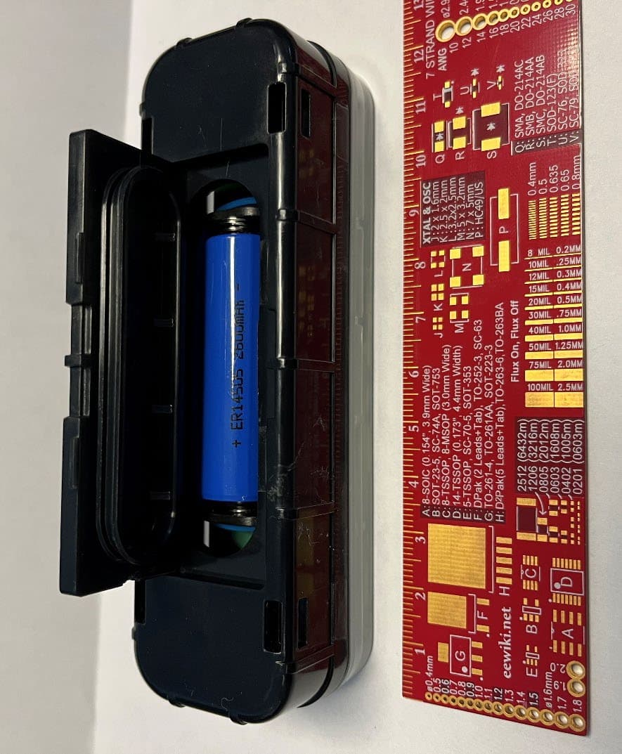
Z9O-53007129
Jan 28, 2026Battery Powered BLE Senso
Equipment Class
DTS - Digital Transmission System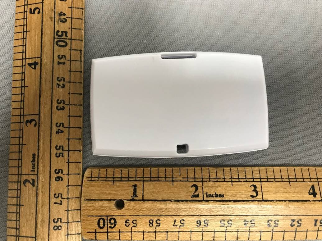
Z9O-53005389
Oct 07, 2023HHCM915-BDG2450
Equipment Class
DXX - Part 15 Low Power Communication Device Transmitter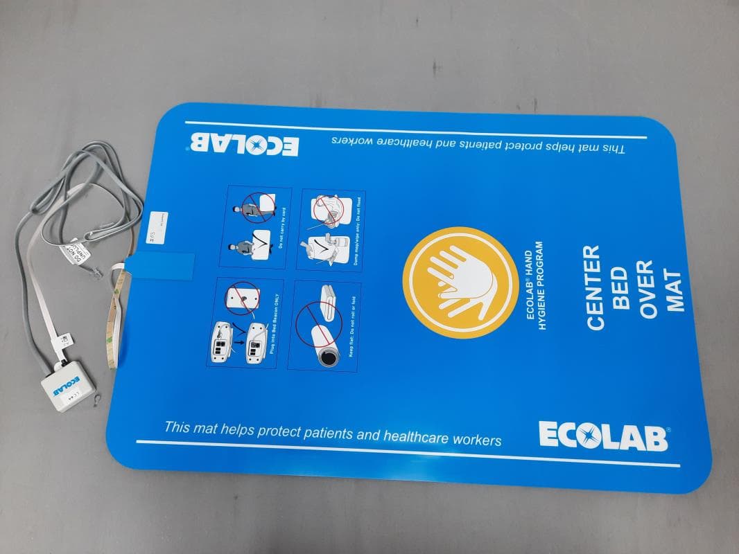
Z9O-92053072
Apr 12, 2023HHCM915 Bed Beacon
Equipment Class
DCD - Part 15 Low Power Transmitter Below 1705 kHz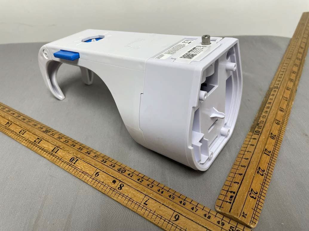
Z9O-92053075
Feb 23, 2022HAND HYGIENE COMPLIANCE MONITORING SYSTEM, 915MHZ, HHCM NEXA POC Holder
Equipment Class
DXT - Part 15 Low Power Transceiver, Rx Verified