Z9O-FAS1521PSS Door Monitor
Ecolab Inc.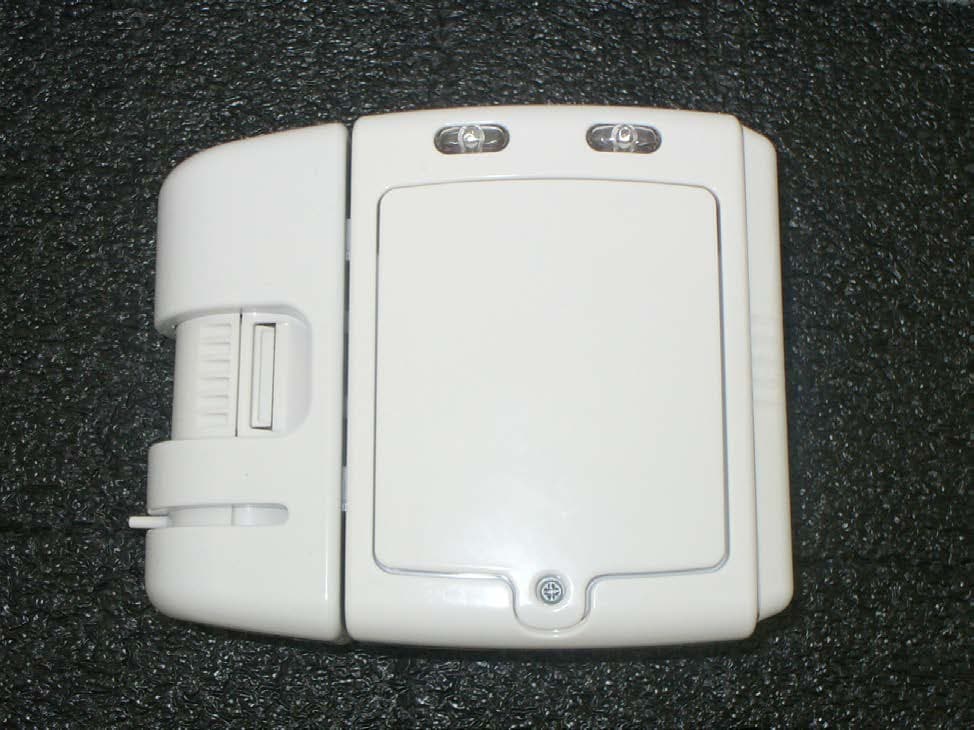
Click to zoom
Application Details
- Equipment Class
- DSR - Part 15 Remote Control/Security Device Transceiver
- Date of Grant
- Jan 28, 2015
- Application Purpose
- Original Equipment
- Date of Application
- Jan 27, 2015
- Equipment Note
- PSS Door Monitor
- Frequency Range
- 433.90000000 - 433.90000000
- Company
- Ecolab Inc.
- Country
- United States
Documents & Files
Document Text
Text extracted from the exhibit documents filed with the FCC. Open a document above to read the original.
Users Manual
Certification Exhibit FCC ID: Z9O-FAS1521 IC: 10060A-FAS1521 FCC Rule Part: 15.231 IC Radio Standards Specification: RSS-210 ACS Project: 14-2067 Manufacturer: UltraClenz, LLC Models: FAS1521-01 User Manual (Part 1 of 2) 3998 FAU Blvd. Suite 310 Boca Raton, FL 33431 Tel: 561-961-5585 Fax: 561-961-5587 PSS Door Monitor PSS Door Monitor User Guide (FAS1521) DOC1059 Revision 2 UltraClenz, LLC DFU Document Title Here UltraClenz, LLC Page 1 Table of Contents `Abstract ...................................................................................................................................................................................... 3 Revision History ........................................................................................................................................................................... 3 Terms, Acronyms and Abbreviations ........................................................................................................................................... 3 1. PSS Door Monitor Features ..................................................................................................................................................... 4 1.1 Component Descriptions - Front View (See Figure 1) ........................................................................................................ 4 1.2 Component Descriptions - Back View (See Figure. 2) ........................................................................................................ 5 2. PSS Door Monitor Led Functionality ........................................................................................................................................ 5 2.1 Hand Hygiene Compliance Warning (Red LED) .................................................................................................................. 5 2.2 Hand Hygiene Compliant - Enter or Exit Area (Green LED) ................................................................................................ 5 2.3 Low Battery Indicator (Red LED) ........................................................................................................................................ 5 2.4 Dead battery Indicator (Red LED) ...................................................................................................................................... 5 3. PSS Door Monitor Configuration Software .............................................................................................................................. 6 3.1 PSS Door Monitor Configuration Software Menu (See Figure.4) ...................................................................................... 6 3.2 Configuration Options........................................................................................................................................................ 7 3.2.1 Operating Mode .......................................................................................................................................................... 7 3.2.2 Mounting Location ...................................................................................................................................................... 7 3.2.3 Interface Options ........................................................................................................................................................ 7 3.2.4 Bypass Mode ............................................................................................................................................................... 7 3.2.5 Alarm Timeout (Increment or Decrement) ................................................................................................................. 7 3.2.6 Pass-through Timeout (Increment or Decrement) ..................................................................................................... 7 3.2.7 Room Entry Counts (Uploaded from the PSS Door Monitor) ..................................................................................... 7 3.2.8 Room Exit Counts (Uploaded from the PSS Door Monitor) ........................................................................................ 8 3.3 Firmware Version (Uploaded from the PSS Door Monitor) ............................................................................................... 8 3.4 Device Address (Uploaded from the PSS Door Monitor) ................................................................................................... 8 3.5 Upload Configuration ......................................................................................................................................................... 8 3.6 Download Configuration .................................................................................................................................................... 8 4. Power-On Self Test Sequence .................................................................................................................................................. 9 5. Entry- Exit Functional Sequences ............................................................................................................................................. 9 6. RS485 to Host Computer ......................................................................................................................................................... 9 7. Changing the PIR Sensor’s Position .......................................................................................................................................... 9 8. PIR Sensor Alignment ............................................................................................................................................................. 10 9. Door Mounting Location ........................................................................................................................................................ 11 Appendix A - USB to RS485 Conv…
Text truncated - open the document above for the full version.
Users Manual
Certification Exhibit FCC ID: Z9O-FAS1521 IC: 10060A-FAS1521 FCC Rule Part: 15.231 IC Radio Standards Specification: RSS-210 ACS Project: 14-2067 Manufacturer: UltraClenz, LLC Models: FAS1521-01 User Manual (Part 2 of 2) 3998 FAU Blvd. Suite 310 Boca Raton, FL 33431 Tel: 561-961-5585 Fax: 561-961-5587 DFU Document Title Here 4. Power-On Self Test Sequence When batteries are installed in the PSS Door Monitor LED, single flash red LED, single flash green LED, single flash red LED, 5. Entry- Exit Functional Sequences Door Entry (Compliant) • Activate the hand sanitizer dispenser • The PSS Door Monitor will flash one green • Enter room Door Exit (Compliant) • Exit the room • PSS Door Monitor red LED will flash • Activate the hand sanitizer • The green LED will flash once 6. RS485 to Host Computer The USB to RS485 Network Interface Kit (part number FAS1502 computer. (See Figures 3 and 5 for the location of the 7. Changing the PIR Sensor’s Position The PIR Sensor can be swapped from the right (See Figures 6, 7and 8) On Self Test Sequence PSS Door Monitor, a power on self test sequence initiates as follows: single flash green LED, single flash red LED, single flash green LED, single flash red LED, and three audible alarm beeps. Exit Functional Sequences anitizer dispenser will flash one green LED h Interface Kit (part number FAS1502-00) is used to connect the PSS Door Monitor computer. (See Figures 3 and 5 for the location of the RS485 connector) Figure 5. RS485 Din Connector Changing the PIR Sensor’s Position The PIR Sensor can be swapped from the right side to the left side depending on the door opening configuration. Figure 6. Right Side PIR RS485 DIN Connector UltraClenz, LLC Page 9 , a power on self test sequence initiates as follows: single flash green and three audible alarm beeps. PSS Door Monitor to the Host side depending on the door opening configuration. RS485 DIN Connector DFU Document Title Here 8. PIR Sensor Alignment The sensor alignment is adjusted by loosening the 1/8” hex screw above the PIR window and by rotating adjustment tab at the bottom of the PIR sensor window room’s door frame or entry path. (See Figures 9 and 10) Figure 7. Left Side PIR Figure 8. PIR Connector is adjusted by loosening the 1/8” hex screw above the PIR window and by rotating adjustment tab at the bottom of the PIR sensor window. It must be positioned so that the PIR window is aimed across the room’s door frame or entry path. (See Figures 9 and 10) Figure 9. Turret Locking Screw PIR Sensor Connector UltraClenz, LLC Page 10 is adjusted by loosening the 1/8” hex screw above the PIR window and by rotating the turret with the so that the PIR window is aimed across the PIR Sensor Connector DFU Document Title Here Figure 10. 9. Door Mounting Location The PSS Door Monitor can be mounted on the wall outside or inside opening. The mounting location of the PSS Door Monitor mounting height and horizontal mounting is button at the top and PIR sensor aiming across making sure the PRI sensor window is clear of door molding and all o Figure 10. PIR Sensor Alignment Tab can be mounted on the wall outside or inside and left or right side of the PSS Door Monitor can be at approximately the same height as the hand dispenser mounting height and horizontal mounting is 2 to 3 inches from entry path. Mount the PSS Door Monitor button at the top and PIR sensor aiming across the door opening. The PSS Door Monitor must be mounted off the wall making sure the PRI sensor window is clear of door molding and all other obstructions (See Figure. 11) Figure 11. Mounting Example UltraClenz, LLC Page 11 left or right side of the patient room’s door the same height as the hand dispenser PSS Door Monitor with bypass must be mounted off the wall ther obstructions (See Figure. 11). DFU Document Title Here UltraClenz, LLC Page 12 Appendix A - USB to RS485 Converter Installation Introduction The USB to RS485 Converter allows the connection of Windows PC based application software to an UltraClenz RS-485 enabled device. The USB to RS485 Converter connects directly to the host PC’s USB port via an A-B USB cable. Power for this device is provided by the PC’s USB port so no external power source is required. The USB to RS485 Converter connects to an RS-485 network via an RJ-11 connector or directly to an UltraClenz device’s data port via a 6-pin MiniDIN cable. Both an RJ-11 and 6-pin MiniDIN connection are provided on the USB to RS485 Converter. Host PC Requirements • Windows XP, Windows 7 or Windows 8 • One Available USB High-Speed (2.0) or Full-Speed Port (3.0) • 1MB of Available Hard Drive Space • Minimum 128M of RAM Installation Follow the steps below to connect the USB to RS485 Converter to the host PC and load the USB driver. The following steps are shown for Windows XP but Windows 7 and 8 are similar. It is possible that Windows 7 or Windows 8 may already have the driver installed. If the Found New Hardware Wizard does not activate, then this is the case and the user may then skip the installation section and go on to configuration section. 1. Locate an available USB port on the host PC 2. Attach the USB cable to the PC’s USB port 3. Attach the other end of the USB cable to the USB to RS485 Converter 4. Window’s “Found New Hardware” Wizard will activate automatically 5. In the Wizard, select “No, not this time” then click Next 6. Insert the USB driver CD into the CD drive 7. Select “Install software automatically (Recommended)” then click Next 8. Click Finish to complete the driver installation After clicking finish, the “Found New Hardware” Wizard will activate again to install the COM port emulation driver. The procedure is the same as that above for installing the USB driver. The above steps need only be performed the first time the USB to RS485 Converter is attached to the host PC. Once the drivers are installed, the host PC will always recognize the USB device. DFU Document Title Here UltraClenz, LLC Page 13 Configuration The USB to RS…
Text truncated - open the document above for the full version.
Cover Letter(s)
5015 B. U. Bowman Dr. Buford, GA 30518 ACS TCB 5015 B.U. Bowman Drive Buford, GA 30518 Re: FCC ID: Z9O-FAS1521 To Whom It May Concern: The following application is submitted on behalf of our client, UltraClenz LLC, for evaluation of their model FAS1521-01for certification under FCC Part 15.231. The UltraClenz LLC PSS door monitor, model FAS1521-01, is a 433 MHz battery operated transceiver. The device is designed to track healthcare worker hand hygiene compliance with respect to a specific hospital room, by recording whether or not a soap or sanitizer dispenser was used during patient room entries and exits. The FCC ID: Z9O-FAS1521 was tested in full to the aforementioned test requirements and was found to be in compliance. Sincerely, Sam Wismer Vice President, Technology Advanced Compliance Solutions, Inc.
External Photos
Certification Exhibit FCC ID: Z9O-FAS1521 IC: 10060A-FAS1521 FCC Rule Part: 15.231 IC Radio Standards Specification: RSS-210 ACS Project: 14-2067 Manufacturer: UltraClenz, LLC Model: FAS1521-01 External Photos 3998 FAU Blvd. Suite 310 Boca Raton, FL 33431 Tel: 561-961-5585 Fax: 561-961-5587 Model: FAS1521-01 FCC ID: Z9O-FAS1521 IC: 10060A-FAS1521 Figure 1: Front View ACS Project: 14-2067 Advanced Compliance Solutions Page 2 Model: FAS1521-01 FCC ID: Z9O-FAS1521 IC: 10060A-FAS1521 Figure 2: Rear View ACS Project: 14-2067 Advanced Compliance Solutions Page 3 Model: FAS1521-01 FCC ID: Z9O-FAS1521 IC: 10060A-FAS1521 Figure 3: Bottom View ACS Project: 14-2067 Advanced Compliance Solutions Page 4 Model: FAS1521-01 FCC ID: Z9O-FAS1521 IC: 10060A-FAS1521 Figure 4: Top View ACS Project: 14-2067 Advanced Compliance Solutions Page 5 Model: FAS1521-01 FCC ID: Z9O-FAS1521 IC: 10060A-FAS1521 Figure 5: Right Side View ACS Project: 14-2067 Advanced Compliance Solutions Page 6 Model: FAS1521-01 FCC ID: Z9O-FAS1521 IC: 10060A-FAS1521 Figure 6: Left Side View ACS Project: 14-2067 Advanced Compliance Solutions Page 7
ID Label/Location Info
Certification Exhibit FCC ID: Z9O-FAS1521 IC: 10060A-FAS1521 FCC Rule Part: 15.231 IC Radio Standards Specification: RSS-210 ACS Project: 14-2067 Manufacturer: UltraClenz, LLC Models: FAS1521-01 Label Information 3998 FAU Blvd. Suite 310 Boca Raton, FL 33431 Tel: 561-961-5585 Fax: 561-961-5587 FCC Label for the PSS Door Monitor FAS1521 FCC Label location for FAS1521 FCC ID: Z9O-FAS1521, IC: 10060A-FAS1521, MODEL:FAS1521-01 THIS DEVICE COMPLIES WITH PART 15 OF THE FCC RULES. OPERATION IS SUBJECT TO THE FOLLOWING TWO CONDITIONS. (1) THIS DEVICE MAY NOT CAUSE HARMEFUL INTERFERENCE, AND (2) THIS DEVICE MUST ACCEPT ANY INTERFERENCE RECIEVED, INCLUDING INTERFERENCE THAT MAY CAUSE UNDESIRED OPERATION. FCC Label location for FAS1521
Internal Photos
Certification Exhibit FCC ID: Z9O-FAS1521 IC: 10060A-FAS1521 FCC Rule Part: 15.231 IC Radio Standards Specification: RSS-210 ACS Project: 14-2067 Manufacturer: UltraClenz, LLC Models: FAS1521-01 Internal Photos 3998 FAU Blvd. Suite 310 Boca Raton, FL 33431 Tel: 561-961-5585 Fax: 561-961-5587 PSS Door Monitor Pictures (FAS1521) Passive infrared Sensor
Test Report
Certification Test Report FCC ID: Z9O-FAS1521 IC: 10060A-FAS1521 FCC Rule Part: 15.231 IC Radio Standards Specification: RSS-210 ACS Report Number: 14-2067.W06.1A Manufacturer: UltraClenz, LLC Model(s): FAS1521-01 Test Begin Date: November 14, 2014 Test End Date: November 14, 2014 Report Issue Date: December 23, 2014 FOR THE SCOPE OF ACCREDITATION UNDER CERTIFICATE NUMBER AT-1533 This report must not be used by the client to claim product certification, approval, or endorsement by ACLASS, ANSI, or any agency of the Federal Government. Reviewed by: Thierry Jean-Charles EMC Engineer Advanced Compliance Solutions, Inc. . This test report shall not be reproduced except in full. This report may be reproduced in part with prior written consent of ACS, Inc. The results contained in this report are representative of the sample(s) submitted for evaluation. This report contains 14 pages 3998 FAU Blvd. Suite 310 Boca Raton, FL 33431 Tel: 561-961-5585 Fax: 561-961-5587 TABLE OF CONTENTS 1 GENERAL ...................................................................................................... 3 1.1 Purpose .............................................................................................................................................. 3 1.2 Product description .......................................................................................................................... 3 1.3 Test Methodology and Considerations ........................................................................................... 3 2 TEST FACILITIES .......................................................................................... 4 2.1 Location ............................................................................................................................................. 4 2.2 Laboratory Accreditations/Recognitions/Certifications ............................................................... 4 2.3 Radiated & Conducted Emissions Test Site Description .............................................................. 5 3 APPLICABLE STANDARD REFERENCES................................................... 6 4 LIST OF TEST EQUIPMENT .......................................................................... 7 5 SUPPORT EQUIPMENT ................................................................................ 8 6 EQUIPMENT UNDER TEST SETUP BLOCK DIAGRAM .............................. 8 6.1 Antenna Requirement – FCC: Section 15.203 ............................................................................... 9 6.2 20dB / 99% Bandwidth: FCC: Section 15.231 (c)(1) / IC RSS-210.A.1.1.3 ................................. 9 6.3 Radiated Spurious Emissions – FCC: Section 15.231 (b)/ IC: RSS-210 A1.1.2..........................11 6.4 Periodic Operation – FCC: CFR 47 15.231(a) / IC: RSS-210 A1.1.1 ..........................................13 7 CONCLUSION .............................................................................................. 13 3998 FAU Blvd. Suite 310 Boca Raton, FL 33431 Tel: 561-961-5585 Fax: 561-961-5587 Model(s): FAS1521-01 FCC ID: Z9O-FAS1521 IC: 10060A-FAS1521 1 GENERAL 1.1 Purpose The purpose of this report is to demonstrate compliance with Part 15 Subpart C of the FCC’s Code of Federal Regulations and Industry Canada’s Radio Standards Specification RSS-210. 1.2 Product description The model FAS1521-01 PSS Door Monitor is designed to track healthcare worker had hygiene compliance with respect to a specific hospital room, by recording whether or not a soap or sanitizer was used during patient room entries and exits. Technical Details Frequency of Operation: 433.9 MHz Number of Channels: 1 Modulation: FSK Data Rate: 250 kbps Antenna / Gain: 1/4 Wave Monopole Antenna / -2.3 dBi Input Voltage: 3 VDC (Size D battery) Manufacturer Information: UltraClenz, LLC 1201 Jupiter Park Drive Jupiter, FL 33458 Test Sample Serial Number(s): 1301-001A-000024 Test Sample Condition: Good 1.3 Test Methodology and Considerations The EUT was evaluated in the orientation of typical orientation for the adujstable sensor set to the right and to the left side of the equipment. The test report documents the configuration leading to the highest emissions. The unit was continually pulsing during the evaluation. The unintentional emissions evaluation is documented separately in a verification test report. ACS Report: 14-2067.W06.1A Advanced Compliance Solutions Page 3 of 14 Model(s): FAS1521-01 FCC ID: Z9O-FAS1521 IC: 10060A-FAS1521 2 TEST FACILITIES 2.1 Location The radiated and conducted emissions test sites are located at the following address: Advanced Compliance Solutions, Inc. 3998 FAU Blvd, Suite 310 Boca Raton, Florida 33431 Phone: (561) 961-5585 Fax: (561) 961-5587 www.acstestlab.com FCC Test Firm Registration #: 475089 Industry Canada Lab Code: 4175C 2.2 Laboratory Accreditations/Recognitions/Certifications ACS is accredited to ISO/IEC 17025 by ANSI-ASQ National Accreditation Board under their ACLASS program and has been issued certificate number AT-1533 in recognition of this accreditation. Unless otherwise specified, all test methods described within this report are covered under the ISO/IEC 17025 scope of accreditation. ACS Report: 14-2067.W06.1A Advanced Compliance Solutions Page 4 of 14 Model(s): FAS1521-01 FCC ID: Z9O-FAS1521 IC: 10060A-FAS1521 2.3 Radiated & Conducted Emissions Test Site Description 2.3.1 Semi-Anechoic Chamber Test Site The EMC radiated test facility consists of an RF-shielded enclosure. The interior dimensions of the indoor semi-anechoic chamber are approximately 48 feet (14.6 m) long by 36 feet (10.8 m) wide by 24 feet (7.3 m) high and consist of rigid, 1/8 inch (0.32 cm) steel-clad, wood core modular panels with steel framing. In the shielded enclosure, the faces of the panels are galvanized and the chamber is self-supporting. 8-foot RF absorbing cones are installed on 4 walls and the ceiling. The steel-clad ground plane is covered with vinyl floor. The turntabl…
Text truncated - open the document above for the full version.
Test Setup Photos
Certification Exhibit FCC ID: Z9O-FAS1521 IC: 10060A-FAS1521 FCC Rule Part: 15.231 IC Radio Standards Specification: RSS-210 ACS Project: 14-2067 Manufacturer: UltraClenz, LLC Model: FAS1521-01 Test Setup Photos 3998 FAU Blvd. Suite 310 Boca Raton, FL 33431 Tel: 561-961-5585 Fax: 561-961-5587 Model: FAS1521-01 FCC ID: Z9O-FAS1521 IC: 10060A-FAS1521 Figure 1: Radiated Emissions – Front View ACS Project: 14-2067 Advanced Compliance Solutions Page 2 Model: FAS1521-01 FCC ID: Z9O-FAS1521 IC: 10060A-FAS1521 Figure 2: Radiated Emissions – Back View ACS Project: 14-2067 Advanced Compliance Solutions Page 3
Contact Information
Applicant
Sherri Tischler(Sr Mgr Regulatory Affairs)
Test Firm
TUV SUD America, Inc.Sam Wismer
Technical Specifications
| # | Rule Parts | Frequency Range | Power Output |
|---|---|---|---|
| 1 | 15.231 | 433.9 MHz - 433.9 MHz | - |
Other Applications from Ecolab Inc.
Z9O-53006187
Apr 21, 2026ULTRA ZONE MONITOR
Equipment Class
DSS - Part 15 Spread Spectrum Transmitter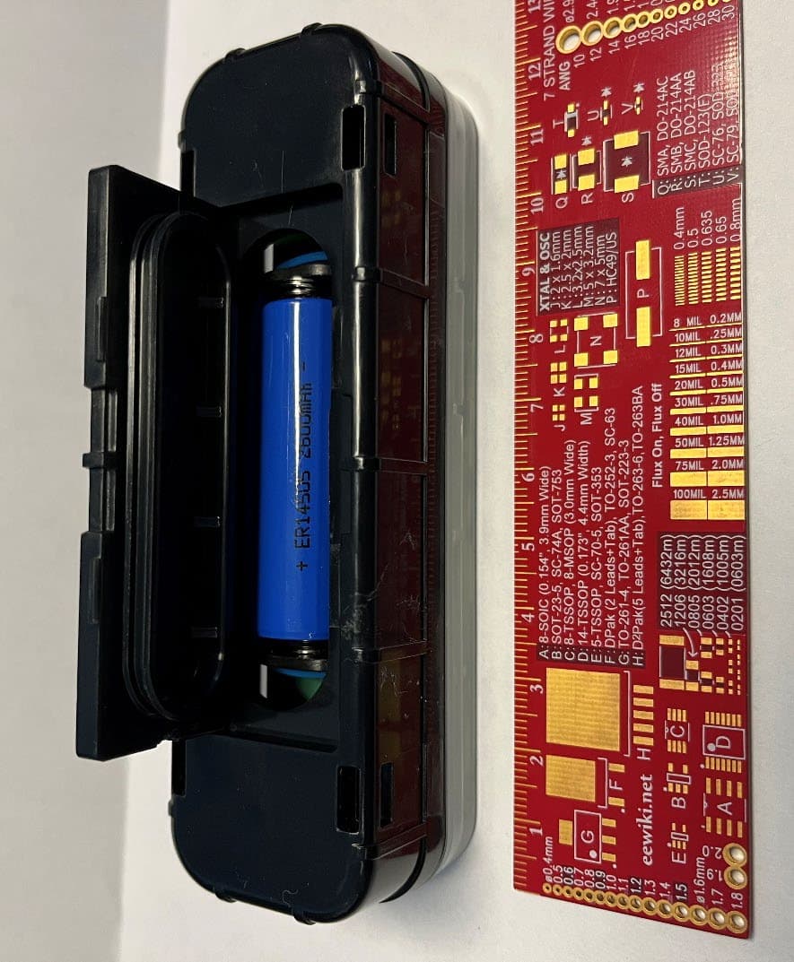
Z9O-53007129
Jan 28, 2026Battery Powered BLE Senso
Equipment Class
DTS - Digital Transmission System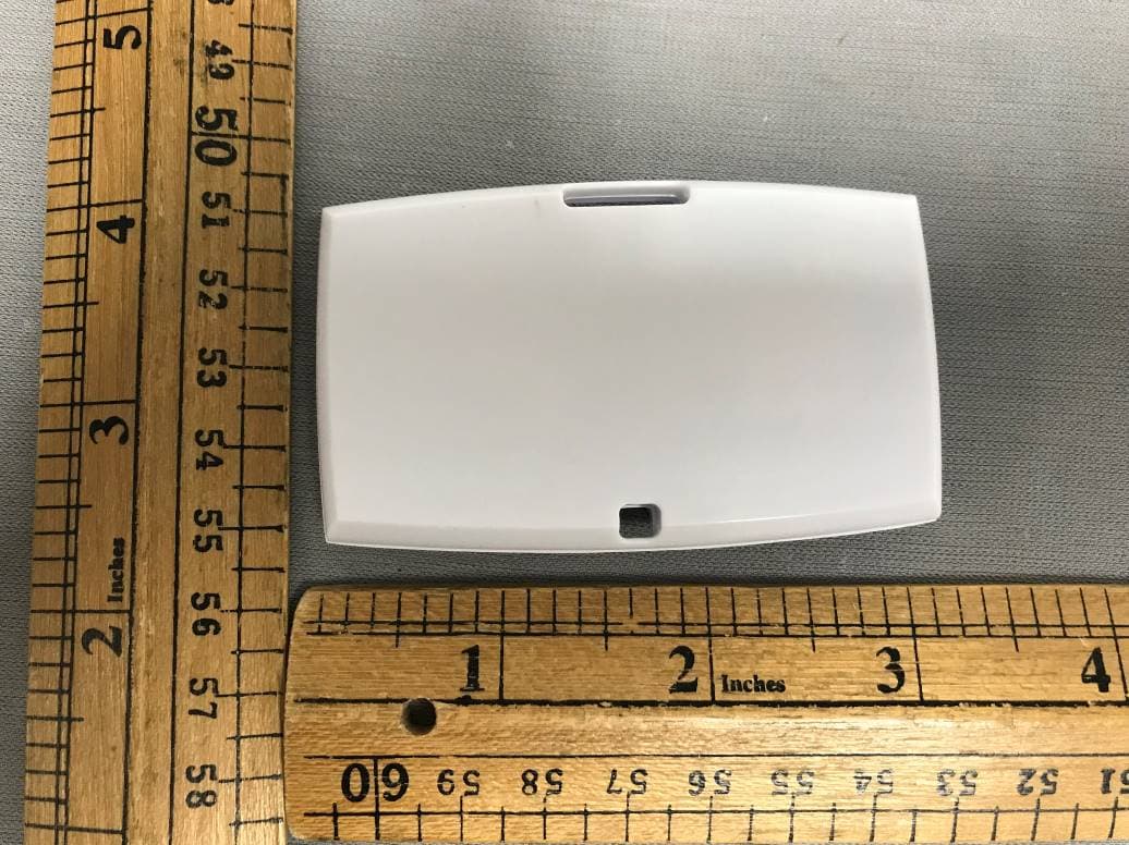
Z9O-53005389
Oct 07, 2023HHCM915-BDG2450
Equipment Class
DXX - Part 15 Low Power Communication Device Transmitter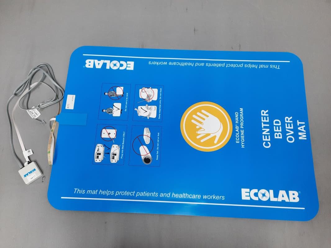
Z9O-92053072
Apr 12, 2023HHCM915 Bed Beacon
Equipment Class
DCD - Part 15 Low Power Transmitter Below 1705 kHz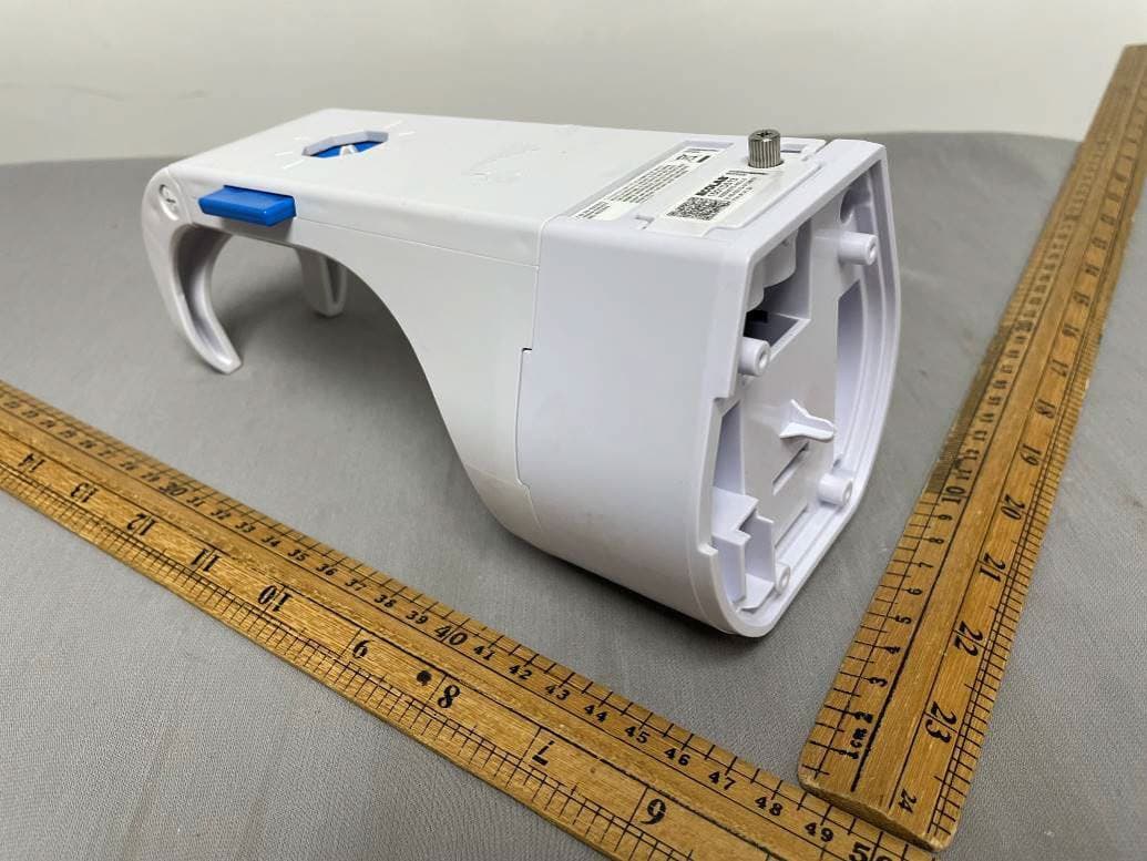
Z9O-92053075
Feb 23, 2022HAND HYGIENE COMPLIANCE MONITORING SYSTEM, 915MHZ, HHCM NEXA POC Holder
Equipment Class
DXT - Part 15 Low Power Transceiver, Rx Verified