Z9W-TNA-30160GHz PTP and PTMP fixed wireless device
8devices
Click to zoom
Application Details
- Equipment Class
- DXX - Part 15 Low Power Communication Device Transmitter
- Date of Grant
- Mar 21, 2023
- Application Purpose
- Original Equipment
- Date of Application
- Mar 21, 2023
- Equipment Note
- 60GHz PTP and PTMP fixed wireless device
- Frequency Range
- 58320.00000000 - 69120.00000000
- Company
- 8devices
- Country
- Lithuania
Documents & Files
Document Text
Text extracted from the exhibit documents filed with the FCC. Open a document above to read the original.
Users Manual
10/20/22, 10:43 AMTNA-30x Operating Manual : Support & Learning Portal https://tachyon-networks.freshdesk.com/support/solutions/articles/67000670226-tna-30x-operating-manual1/8 TNA-30x Operating Manual Modified on: Mon, 10 Oct, 2022 at 2:33 PM This operating manual applies to the TNA-301 and TNA-302 product models. Table of contents Product box contents Meaning of device LEDs Powering your device Device access for initial configuration Making a link Troubleshooting your link Updating firmware Resetting your device Mounting your device i Note: Please be patient the first time you power on your device, as it make take more time than normal to boot up while the device flashes its internal modem firmware. Three blinking signal LEDs will indicate that this process is currently in progress, and should last about 30 seconds to 1 minute. Product box contents Please consider recycling our eco-friendly product packaging. ItemQty TNA-301 or TNA-302 60 GHz unit w/ attached mounting back plate1 PoE adapter and power cable1 Quick start guide insert Meaning of device LEDs 10/20/22, 10:43 AMTNA-30x Operating Manual : Support & Learning Portal https://tachyon-networks.freshdesk.com/support/solutions/articles/67000670226-tna-30x-operating-manual2/8 Signal level LEDs Signal LEDs are updated at a ~4 second interval. BehaviorMeaning All signal LEDs are offThe device is currently operating in AP mode, or the device is powered off. The first LED is on & slowly blinkingThe device is in station mode and is currently scanning. All three LEDs are on & fast blinking The device is currently updating its modem firmware. This only happens at boot after a firmware upgrade. The first LED is on and not blinking The device is in station mode and currently connected to an AP with low signal strength. The first two LEDs are on, not blinking The device is in station mode and currently connected to an AP with medium signal strength. All three LEDs are on, not blinking The device is in station mode and currently connected to an AP with high signal strength. Ethernet port LEDs 2.5G ETH0: The link light will turn on when a link is established, and the power light will turn on once the device is supplied with power. 1G ETH1: The link light will turn on and blink when a link is established, and the PoE out light will turn on when PoE out is enabled in software. Powering your device Input Power i The input power should be 48VDC and a minimum of .5A (24W) is recommended. The TNA-30x can be powered two ways, either via: 1. The Power over Ethernet (PoE) port or via 2. The DC input terminal. 10/20/22, 10:43 AMTNA-30x Operating Manual : Support & Learning Portal https://tachyon-networks.freshdesk.com/support/solutions/articles/67000670226-tna-30x-operating-manual3/8 Both powering methods should not be used at the same time. The input power should be 48VDC in both cases and a minimum of .5A (24W) is recommended. Although not recommended, a lower input voltage may be used (as low as 24VDC). However, there are two main limitations when using a lower input voltage: The cable run should be as short as possible and the use of larger gauge cable such as CAT6+ is highly recommended. On longer cable runs, the voltage drop will be higher due to the higher current needed to meet the needs of the radio. The PoE out is current-limited to .5A. At 24VDC, this is insufficient power for a second TNA-30x. Output Power The TNA-30x has the ability to send passive PoE out of the 1Gbps port to power another device using the input power provided to the TNA-30x. These settings can be found under the Network/Ethernet PoE Out section of the Web UI. The output voltage is the same as the input voltage and supports a maximum of .5A of current (24W total). ! Warning: when using the PoE out feature on the TNA-30x, care should be taken to ensure there is adequate power supply to power both the TNA-30x and the secondary device. The supplied PoE injector may not be adequate to power both devices and may result in unstable operation. ! Warning: passive PoE out on the 1Gbps port can damage non-PoE devices. Do not connect non-PoE devices to the 1Gbps port when PoE out is enabled. Device access for initial configuration i You will need a modern web browser in order to access the device's Web UI to configure your device. 1. First, power on the device. You can do this by using the DC input terminal or by using the included PoE adapter. If using the PoE adapter, plug the power cable attached to the PoE adapter into the wall. Next, plug one side of an ethernet cable into the adapter’s POE port, and the other into the device’s 2.5G ETH0 PoE-in port. 2. Connect your laptop’s ethernet cable into either the data port of the PoE adapter (2.5G) or the ETH1 (1G) port on the device, in order to give your laptop or device connectivity. By default, DHCP client is enabled on the main management network bridge of the device. If your device cannot obtain an IP from an upstream DHCP server, it will fall back to 192.168.1.1, unless otherwise configured. 10/20/22, 10:43 AMTNA-30x Operating Manual : Support & Learning Portal https://tachyon-networks.freshdesk.com/support/solutions/articles/67000670226-tna-30x-operating-manual4/8 3.Log in to your device's local web UI in your web browser at the DHCP-assigned IP, or the fallback IP previously mentioned, using the default credentials of root/admin. Please change the default user credentials after you login for the first time. 4. Go to the configuration settings tab via the main nav menu on the left in order to configure your device. Please refer to the full web UI manual (https://tachyon-networks.freshdesk.com/support/solutions/articles/67000659775-tna-30x- web-ui-manual-v1-10-3-) for details about each setting, or continue reading below about how to make a link. Making a link By default, the TNA-301 is configured to operate in AP mode with the SSID tachyon-ptmp, and the TNA-302 is configured to operate in station mode with the same SSID. This mea…
Text truncated - open the document above for the full version.
Attestation Statements
8devices Add: Antakalnio 17 - 6 Vilnius Lithuania Tel: +37052001014 Email: [email protected] CFR 47 §2.911(d)(5)(i)(ii) Attestation Letter Attestation Letter Date: 2023-02-14 FEDERAL COMMUNICATIONS COMMISSIONS Authorization and Evaluation Division 7435 Oakland Mills Road Columbia, MD 21046 Ref: Attestation Statements CFR 47 §2.911(d)(5)(i)(ii) Filing FCC ID: Z9W-TNA-301 8devices (“the applicant”) certifies that the equipment for which authorization is sought is not “covered” equipment prohibited from receiving an equipment authorization pursuant to section 2.903 of the FCC rules. 8devices (“the applicant”) certifies that as of the date of the filing of the application, the applicant is not identified on the Covered List as an entity producing “covered” equipment. Sincerely, Signature Contact Person: Jonas Sabaliauskas Title: Director Company Name& Address: 8devices& Antakalnio 17 - 6 Vilnius Lithuania
Attestation Statements
Attestation Letter for Agent 2023/02/14 FEDERAL COMMUNICATIONS COMMISSIONS Authorization and Evaluation Division 7435 Oakland Mills Road Columbia, MD 21046 Re f: Attestation Statements Part 2.911 (d)(7) Filing FCC ID: Z9W-TNA-301 8devices certifies that, as of the date of the filing of the application, Iconsigh Inc. is our designated U.S. agent for service of process for the above referenced FCC ID: Z9W-TNA-301 . 8devices agrees to maintain an agent for no less than one year after the grantee has terminated all marketing and importation or the conclusion of any Commission-related proceeding involving the equipment. Iconsigh Inc.accepts, as of the date of the filing of the application, the obligation of the designated U.S. agent for service of process for the above referenced FCC ID. Designated U.S. Agent Information: Company name: Iconsigh Inc. Address: 2310 Homestead Road, Suite C1, Los Altos, CA 94024, USA Contact person: Benjamin Kaur Tel: +1 (408) 320-9867 Email: [email protected] Sincerely, Applicant Name: 8devices U.S. Agent: Iconsigh Inc. Applicant Printed Name: Jonas Sabaliauskas U.S. Agent Printed Name: Benjamin Kaur Applicant Signature: U.S. Agent Signature:
Cover Letter(s)
QA-FR-170-B 8devices Add: Antakalnio 17 - 6 Vilnius Lithuania Tel: +37052001014 Email: [email protected] FCC Authorization Date: 2023-01-16 FEDERAL COMMUNICATIONS COMMISSION Authorization and Evaluation Division 7435 Oakland Mills Road Columbia, MD 21046 Subject: Agent Authorization To whom it may concern: We , 8devices, Hereby authorizes China Certification ICT Co., Ltd (Dongguan) to act on its behalf in all matters relating to application for Equipment authorization, including the signing of all documents relating to these matters. All acts carried out by China Certification ICT Co., Ltd (Dongguan) on our behalf shall have the same effect as our own action. We, the undersigned, hereby certify that we are not subject to a denial of federal benefits, that includes FCC benefits, pursuant to Section 5301 of the Anti-Drug Abuse Act of 1988, 21 U.S.C. 862. This authorization is valid until further written notice from the applicant. Sincerely Yours, Client’s signature Printed Name: Jonas Sabaliauskas Title: Director
Cover Letter(s)
QA-FR-171-A 8devices Add: Antakalnio 17 - 6 Vilnius Lithuania Tel: +37052001014 Email: [email protected] FCC Confidential Authorization Date:2023-01-16 FEDERAL COMMUNICATIONS COMMISSION Authorization and Evaluation Division 7435 Oakland Mills Road Columbia, MD 21046 Subject: Confidentiality Request regarding application for certification of FCC ID: Z9W-TNA-301 In accordance with Sections 0.457 and 0.459 of the Commission’s Rules, (8devices) hereby requests long-term confidential treatment of information accompanying this application as outlined below: •Block Diagram •Schematics •Operation Description The above materials contain proprietary and confidential information not customarily released to the public. The public disclosure of these materials provides unjustified benefits to its competitors in the market. Sincerely, Signature: Printed Name: Jonas Sabaliauskas Title: Director As well as short-term (secrecy cycle: 180 days) confidential treatment of information accompanying this application as outlined below: Internal Photos User’s Manual External Photos Test Set-up Photos
External Photos
EXHIBIT B - EUT EXTERNAL PHOTOGRAPHS Port
Internal Photos
EXHIBIT C - EUT INTERNAL PHOTOGRAPHS Chip1 Chip2 Antenna
RF Exposure Info
China Certification ICT Co., Ltd (Dongguan) Report No.: CR221259869-00A Page 56 of 57 5. RF EXPOSURE EVALUATION 5.1 MAXIMUM PERMISSIBLE EXPOSURE (MPE) 5.1.1 Applicable Standard FCC §15.255(g) & §1.1310 & §2.1091 Regardless of the power density levels permitted under this subpart, devices operating under the provisions of this subpart are subject to the radiofrequency radiation exposure requirements specified in §§ 1.1307(b), 2.1091, and 2.1093 of this chapter, as appropriate. Applications for equipment authorization of devices operating under this section must contain a statement confirming compliance with these requirements for both fundamental emissions and unwanted emissions. Technical information showing the basis for this statement must be submitted to the Commission upon request. Systems operating under the provisions of this section shall be operated in a manner that ensures that the public is not exposed to radio frequency energy levels in excess of the Commission's guidelines. See §1.1307(b)(1) of this chapter. Limits for Maximum Permissible Exposure (MPE) (§1.1310, §2.1091) (B) Limits for General Population/Uncontrolled Exposure Frequency Range (MHz) Electric Field Strength (V/m) Magnetic Field Strength (A/m) Power Density (mW/cm 2 ) Averaging Time (minutes) 0.3–1.34 614 1.63 *(100) 30 1.34–30 824/f 2.19/f *(180/f²) 30 30–300 27.5 0.073 0.2 30 300–1500 / / f/1500 30 1500–100,000 / / 1.0 30 f = frequency in MHz; * = Plane-wave equivalent power density; According to §1.1310 and §2.1091 RF exposure is calculated. 5.1.2 Procedure Prediction of power density at the distance of the applicable MPE limit S = PG/4R² = power density (in appropriate units, e.g. mW/cm 2 ); P = power input to the antenna (in appropriate units, e.g., mW); G = power gain of the antenna in the direction of interest relative to an isotropic radiator, the power gain factor, is normally numeric gain; R = distance to the center of radiation of the antenna (appropriate units, e.g., cm); China Certification ICT Co., Ltd (Dongguan) Report No.: CR221259869-00A Page 57 of 57 5.2 Measurement Result Frequency (GHz) Antenna Gain Conducted output power including Tune-up Tolerance Evaluation Distance (cm) Power Density (mW/cm 2 ) MPE Limit (mW/cm 2 ) (dBi) (numeric) (dBm)(mW) 58.32-69.12 18.00 63.1 1979.43 200.9971 1 Note: The Value of Maximum Conducted Power including Tune-up Tolerance was declared by the customer. Result: The device meet FCC MPE at 20 cm distance. ===== END OF REPORT =====
Test Report
8devices TNA-301 antenna specification Antenna part number: PRM2142 Antenna type: patch array Antenna frequency: 57-71GHz Antenna is built in and cannot be swapped out or changed by customer or technician. Antenna manufacturer: Peraso 2309 Bering Drive San Jose, CA 95131 USA Antenna parameters Antenna gain dBi 18 Azimuth scan range degrees ±45 Elevation scan range degrees ±25 Antenna patterns:
Test Report
TEST REPORT Applicant: 8devices Address: Antakalnio 17 - 6 Vilnius Lithuania FCC ID: Z9W-TNA-301 Product Name: 60GHz PTP and PTMP fixed wireless device Standard(s): 47 CFR Part 15, Subpart C(15.255) ANSI C63.10-2013 The above equipment has been tested and found compliant with the requirement of the relative standards by China Certification ICT Co., Ltd (Dongguan) Report Number: CR221259869-00A Date Of Issue: 2023/3/3 Reviewed By: Sun Zhong Title: Manager Test Laboratory: China Certification ICT Co., Ltd (Dongguan) No. 113, Pingkang Road, Dalang Town, Dongguan, Guangdong, China Tel: +86-769-82016888 China Certification ICT Co., Ltd (Dongguan) Report No.: CR221259869-00A Page 2 of 57 Test Facility The Test site used by China Certification ICT Co., Ltd (Dongguan) to collect test data is located on the No. 113, Pingkang Road, Dalang Town, Dongguan, Guangdong, China. The lab has been recognized as the FCC accredited lab under the KDB 974614 D01 and is listed in the FCC Public Access Link (PAL) database, FCC Registration No. : 442868, the FCC Designation No. : CN1314. The lab has been recognized by Innovation, Science and Economic Development Canada to test to Canadian radio equipment requirements, the CAB identifier: CN0123. Declarations China Certification ICT Co., Ltd (Dongguan) is not responsible for the authenticity of any test data provided by the applicant. Data included from the applicant that may affect test results are marked with a triangle symbol “▲”. Customer model name, addresses, names, trademarks etc. are not considered data. Unless otherwise stated the results shown in this test report refer only to the sample(s) tested. This report cannot be reproduced except in full, without prior written approval of the Company. This report is valid only with a valid digital signature. The digital signature may be available only under the Adobe software above version 7.0. This report may contain data that are not covered by the accreditation scope and shall be marked with an asterisk “★”. China Certification ICT Co., Ltd (Dongguan) Report No.: CR221259869-00A Page 3 of 57 CONTENTS T EST FACILITY .......................................................................................................................................... 2 DECLARATIONS .......................................................................................................................................... 2 DOCUMENT REVISION HISTORY .......................................................................................... 5 1. GENERAL INFORMATION .................................................................................................... 6 1.1 PRODUCT DESCRIPTION FOR EQUIPMENT UNDER TEST (EUT) ....................................................... 6 1.2 DESCRIPTION OF TEST CONFIGURATION ........................................................................................... 7 1.2.2 Support Equipment List and Details .............................................................................................................. 7 1.2.3 Support Cable List and Details ...................................................................................................................... 7 1.2.4 Block Diagram of Test Setup ......................................................................................................................... 8 1.3 FAR FIELD BOUNDARY CALCULATIONS ......................................................................................... 10 1.4 MEASUREMENT UNCERTAINTY ........................................................................................................ 11 2. SUMMARY OF TEST RESULTS .......................................................................................... 12 3. REQUIREMENTS AND TEST PROCEDURES .................................................................. 13 3.1 AC LINE CONDUCTED EMISSIONS .................................................................................................... 13 3.1.1 Applicable Standard ..................................................................................................................................... 13 3.1.2 EUT Setup.................................................................................................................................................... 14 3.1.3 EMI Test Receiver Setup ............................................................................................................................. 14 3.1.4 Test Procedure ............................................................................................................................................. 15 3.1.5 Corrected Amplitude & Margin Calculation ................................................................................................ 15 3.2 RADIATED EMISSIONS ....................................................................................................................... 16 3.2.1 Applicable Standard ..................................................................................................................................... 16 3.2.2 EUT Setup.................................................................................................................................................... 16 3.2.3 EMI Test Receiver & Spectrum Analyzer Setup ......................................................................................... 18 3.2.4 Test Procedure ............................................................................................................................................. 18 3.2.5 Corrected Amplitude & Margin Calculation ................................................................................................ 18 3.3 EMISSION BANDWIDTH: .................................................................................................................... 19 3.3.1 Applicable Standard ...................................................................................…
Text truncated - open the document above for the full version.
Test Setup Photos
EXHIBIT D - TEST SETUP PHOTOGRAPHS Conducted Emissions Front View POE Conducted Emissions Side View POE Conducted Emissions Front View DC Power Conducted Emissions Side View DC Power Radiated Emission Below 1GHz View POE Radiated Emission Below 1GHz View DC Power Radiated Emission 1-18GHz View POE Radiated Emission 18-26.5GHz View POE Radiated Emission 26.5-40GHz View POE Radiated Emission 40-60GHz View POE Radiated Emission 60-90GHz View POE Radiated Emission 90-140GHz View POE Radiated Emission 140-200GHz View POE
Contact Information
Applicant
Jonas Sabaliauskas(Director)
Test Firm
CHINA CERTIFICATION ICT CO., LTD (DONGGUAN)Tanie Ou
[email protected]0086 0769 86858888
Technical Specifications
| # | Rule Parts | Frequency Range | Power Output |
|---|---|---|---|
| 1 | 15C | 58.32 GHz - 69.12 GHz | 4.169 W |
Other Applications from 8devices

Z9W-CM3
Jul 23, 2024Carambola3
Equipment Class
DTS - Digital Transmission SystemZ9W-PIN6
Jul 02, 2024Pineapple 6
Equipment Class
6XD - 15E 6 GHz Low Power Indoor Client
Z9W-AP3
Jun 27, 2023Wireless Access Point
Equipment Class
JAB - Part 15 Class B Digital Device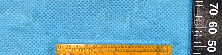
Z9WMAN
Jan 03, 2023Mango
Equipment Class
DTS - Digital Transmission System
Z9W-HAB
Aug 10, 2020Habanero
Equipment Class
NII - Unlicensed National Information Infrastructure TX