ZAS-HQ-HH-002BLE Module
HUSQVARNA AB
Click to zoom
Application Details
- Equipment Class
- DTS - Digital Transmission System
- Date of Grant
- Jun 02, 2020
- Application Purpose
- Original Equipment
- Date of Application
- May 31, 2020
- Equipment Note
- BLE Module
- Frequency Range
- 2402.00000000 - 2480.00000000
- Company
- HUSQVARNA AB
- Country
- Sweden
Documents & Files
Document Text
Text extracted from the exhibit documents filed with the FCC. Open a document above to read the original.
Users Manual
T540i XP ® ENOperator's manual2-31 ES-MXManual del usuario32-63 FR-CAManuel d’utilisation64-96 Contents Introduction.....................................................................2 Safety..............................................................................4 Assembly......................................................................11 Operation......................................................................12 Maintenance.................................................................18 Troubleshooting............................................................26 Transportation, storage and disposal........................... 26 Technical data.............................................................. 27 Accessories.................................................................. 28 Registered trademarks................................................. 29 Warranty.......................................................................30 Introduction Intended use This product is for professional tree maintenance such as pruning and to disassemble trees in sections. Note: National regulations can set limit to the operation of the product. Product description This product is a chainsaw model with an electric motor. Work is constantly in progress to increase your safety and efficiency during operation. Speak to your servicing dealer for more information. Product overview 8 7 2 1 17 1514 232221 201918 12 10 9 35 34 33 32 3130 28 29 27 26 25 24 4 6 3 11 13 16 5 1. Front hand guard and chain brake2. User interface 21036 - 003 - 3. Start/stop button 4. Warning indicator 5. Battery indicator 6. SavE button 7. Information and warning decal 8. Top handle 9. Belt eyelet 10. Rope eyelet 11. Fan housing 12. Front handle 13. Chain oil tank 14. Power trigger lockout 15. Power trigger 16. Oil adjustment screw 17. Spiked bumper 18. Bar tip sprocket 19. Saw chain 20. Guide bar 21. Chain catcher 22. Chain tensioning screw 23. Drive sprocket cover 24. Guide bar cover 25. Indicator for state of charge 26. Warning indicator 27. Power cord 28. Combination wrench 29. Battery charger (accessory) 30. Button, battery status 31. Battery status 32. Warning indicator 33. Battery release button 34. Battery (accessory) 35. Operator's manual Symbols on the product Risk of serious injury or death to the operator or others. Be careful and use the product correctly. Read the operator's manual carefully and understand the instructions before operation of the product. Use approved protective helmet, hearing protection and eye protection. Use approved protection for feet, legs, hands and arms. Use 2 hands when you operate the product. Do not operate the product with 1 hand only. Do not let the guide bar tip touch an object. Warning! Kickback can occur when the guide bar tip touches an object. This causes the guide bar to be thrown in the direction of the operator. Risk of serious injury or death. L-Max XX mm / XX" The direction in which the saw chain rotates and maximum length of the guide bar. Chain brake, engaged (right). Chain brake, disengaged (left). Chain oil. Rated voltage, V. Direct current. Protected against splashing water. XX mm/XX Max XT Husqvarna HXX Recommended cutting equipment in this example: Bar length 14 in (356 mm), max. nose radius 9 Teeth, chain type Husqvarna H38. XX Measured maximum kickback value without triggering the brake, for the bar and chain combination on the label. XX Measured maximum kickback value with brake for the bar and chain combination on the label. Environmental mark. The product or package of the product is not domestic waste. Recycle it at an approved disposal 1036 - 003 - 3 location for electrical and electronic equipment. If the product features Bluetooth ® wireless technology. The Bluetooth ® symbol will be marked on the product name label. Refer to Bluetooth ® wireless technology on page 12. This saw should only be used by persons who are specially trained in tree maintenance work. See operator's manual! yyyywwxxxxx The rating plate shows se- rial number. yyyy is the production year, ww is the production week. Note: Other symbols/decals on the product refer to certification requirements for some markets. Symbol in the manual The symbol that follows is only used in illustrations of this operator's manual. Warning! Kickback can occur when the guide bar tip touches an object. This causes the guide bar to be thrown in the direction of the operator. Risk of serious injury or death. Symbols on the battery and/or on the battery charger Recycle this product at a recy- cling station for electrical and electronic equipment. (Applies to Europe only) Fail-safe transformer. Use and keep the battery charger indoors only. Double insulation. California Proposition 65 Manufacturer Husqvarna AB Drottninggatan 2, SE.561 82 Huskvarna, Sweden, tel: +46-36-146500 Product liability As referred to in the product liability laws, we are not liable for damages that our product causes if: • the product is incorrectly repaired. • the product is repaired with parts that are not from the manufacturer or not approved by the manufacturer. • the product has an accessory that is not from the manufacturer or not approved by the manufacturer. • the product is not repaired at an approved service center or by an approved authority. Safety Safety definitions Warnings, cautions and notes are used to point out specially important parts of the manual. WARNING: Used if there is a risk of injury or death for the operator or bystanders if the instructions in the manual are not obeyed. CAUTION: Used if there is a risk of damage to the product, other materials or the adjacent area if the instructions in the manual are not obeyed. Note: Used to give more information that is necessary in a given situation. 41036 - 003 - General power tool safety warnings WARNING: Read all safety warnings, instructions, illustrations and specifications provided with this power tool. Failure to follow all instructions lis…
Text truncated - open the document above for the full version.
Users Manual
Installation Manual HMI Bluetooth® Modules 1 (2) UI Medium (ZAS-HQ-HH-001) UI Small (ZAS-HQ-HH-002) In addition to technical implementation specifications, the following instructions shall be followed when implementing the HMI modules incorporating Bluetooth® functionality, i.e. the UI Medium and UI Small, for the below mentioned certifications to be valid. 1 - Compliance This device complies with Part 15 of the FCC Rules and with Industry Canada licensee exempt RSS standard(s). Operation is subject to the following two conditions: • this device may not cause harmful interference, and • this device must accept any interference received, including interference that may cause undesired operation. Le présent appareil est conforme aux CNR d'Industrie Canada applicables aux appareils radio exempts de licence. L'exploitation est autorisée aux deux conditions suivantes: • l'appareil ne doit pas produire de brouillage, et • l'appareil doit accepter tout brouillage radioélectrique subi, même si le brouillage est susceptible d'en compromettre le fonctionnement. Changes or modifications made to this equipment not expressly approved by Husqvarna may void the FCC authorization to operate this equipment. Installation Manual HMI Bluetooth® Modules 2 (2) 2 - Modular Approval (FCC Part 15) Both UI Medium (ZAS-HQ-HH-001) and UI Small (ZAS-HQ-HH-002) is of the type Limited single-modular transmitter. Due to lack of shielding on the module itself, each product using the module need to be measured to comply with FCC Part 15. 3– Product Labeling For products using the modules UI Medium (ZAS-HQ-HH-001) and UI Small (ZAS-HQ-HH- 002) the host product need to be labeled accordingly to comply. For UI Medium (ZAS HQ-HH-001): Marking with the wording “THIS PRODUCT CONTAINS” followed by and on a separate line “FCC ID: ZAS-HQ-HH-001” and again on a separate line “IC: 23307-HQHH001”. For UI Small (ZAS HQ-HH-002): Marking with the wording “THIS PRODUCT CONTAINS” followed by and on a separate line “FCC ID: ZAS-HQ-HH-002” and again on a separate line “IC: 23307-HQHH002”.
Cover Letter(s)
Applicant/Grantee Husqvarna AB FCC ID: ZAS-HQ-HH-002 Section 15.212 Modular Transmitters Request for Modular Approval Request for Limited Modular Approval Requirements EUT Conditions Comply (Y/N) Single Modular Approval Requirements 1 The radio elements of the modular transmitter must have their own shielding. The physical crystal and tuning capacitors may be located external to the shielded radio elements. Module will be tested in host product. No 2 The modular transmitter must have buffered modulation/data inputs (if such inputs are provided) to ensure that the module will comply with Part 15 requirements under conditions of excessive data rates or over-modulation. Yes 3 The modular transmitter must have its own power supply regulation. Yes 4 The modular transmitter must comply with the antenna and transmission system requirements of Sections 15.203, 15.204(b) and 15.204(c). The antenna must either be permanently attached or employ a “unique” antenna coupler (at all connections between the module and the antenna, including the cable). The “professional installation” provision of Section 15.203 is not applicable to modules but can apply to limited modular approvals under paragraph (b) of this section. Yes 5 The modular transmitter must be tested in a stand-alone configuration, i.e., the module must not be inside another device during testing for compliance with Part 15 requirements. Unless the transmitter module will be battery powered, it must comply with the AC line conducted requirements found in Section 15.207. AC or DC power lines and data input/output lines connected to the module must not contain ferrites, unless they will be marketed with the module (see Section 15.27(a)). The length of these lines shall be the length typical of actual use or, if that length is unknown, at least 10 centimeters to insure that there is no coupling between the case of the module and supporting Yes equipment. Any accessories, peripherals, or support equipment connected to the module during testing shall be unmodified and commercially available (see Section 15.31(i)). 6 The modular transmitter must be equipped with either a permanently affixed label or must be capable of electronically displaying its FCC identification number. (A) If using a permanently affixed label, the modular transmitter must be labeled with its own FCC identification number, and, if the FCC identification number is not visible when the module is installed inside another device, then the outside of the device into which the module is installed must also display a label referring to the enclosed module. This exterior label can use wording such as the following: “Contains Transmitter Module FCC ID: XYZMODEL1” or “Contains FCC ID: XYZMODEL1.” Any similar wording that expresses the same meaning may be used. The Grantee may either provide such a label, an example of which must be included in the application for equipment authorization, or, must provide adequate instructions along with the module which explain this requirement. In the latter case, a copy of these instructions must be included in the application for equipment authorization. (B) If the modular transmitter uses an electronic display of the FCC identification number, the information must be readily accessible and visible on the modular transmitter or on the device in which it is installed. If the module is installed inside another device, then the outside of the device into which the module is installed must display a label referring to the enclosed module. This exterior label can use wording such as the following: “Contains FCC certified transmitter module(s).” Any similar wording that expresses the same meaning may be used. The user manual must include instructions on how to access the electronic display. A copy of these instructions must be included in the application for equipment authorization. Yes 7 The modular transmitter must comply with any specific rules or operating requirements that ordinarily apply to a complete transmitter and the manufacturer must provide adequate instructions along with the module to explain any such requirements. A copy of these instructions must be included in the application for equipment authorization. Yes 8 The modular transmitter must comply with any applicable RF exposure requirements in its final configuration. Yes A limited modular approval may be granted for single or split modular transmitters that do not comply with all of the above requirements, e.g., shielding, minimum signaling amplitude, buffered modulation/data inputs, or power supply regulation, if the manufacturer can demonstrate by alternative means in the application for equipment authorization that the modular transmitter meets all the applicable Part 15 requirements under the operating conditions in which the transmitter will be used. Limited modular approval also may be granted in those instances where compliance with RF exposure rules is demonstrated only for particular product configurations. The applicant for certification must state how control of the end product into which the module will be installed will be maintained such that full compliance of the end product is always ensured.
RF Exposure Info
NVLAP LAB CODE 200246-0 FCC Part 1 Subpart I FCC Part 2 Subpart J ISED RSS-102 ISSUE 5 RF EXPOSURE REPORT FOR BLE MODULE MODEL NAME: HQ-HH-002 FCC ID: ZAS-HQ-HH-002 IC ID: 23307-HQHH002 REPORT NUMBER: R12790693-E3 ISSUE DATE: 2020-05-01 Prepared for HUSQVARNA AB EM-FHR HUSKVARNA, SE-561 82 SWEDEN Prepared by UL LLC 12 LABORATORY DR. RESEARCH TRIANGLE PARK, NC 27709 USA TEL: (919) 549-1400 REPORT NO: R12790693-E3 DATE: 2020-05-01 FCC ID: ZAS-HQ-HH-002 IC ID: 23307-HQHH002 Page 2 of 7 UL Verification Services Inc. Doc. No.: 1.0 This report shall not be reproduced without the written approval of UL Verification Services Inc. . Revision History Ver. Issue Date Revisions Revised By 1 2019-08-15 Initial Issue Brian T. Kiewra 2 2020-05-01 Revised model name Lariah Ijames REPORT NO: R12790693-E3 DATE: 2020-05-01 FCC ID: ZAS-HQ-HH-002 IC ID: 23307-HQHH002 Page 3 of 7 UL Verification Services Inc. Doc. No.: 1.0 This report shall not be reproduced without the written approval of UL Verification Services Inc. . TABLE OF CONTENTS 1. ATTESTATION OF TEST RESULTS ..................................................................................4 2. TEST METHODOLOGY ......................................................................................................5 3. REFERENCES ....................................................................................................................5 4. FACILITIES AND ACCREDITATION ..................................................................................5 5. DEVICE UNDER TEST ........................................................................................................5 6. STANDALONE SAR TEST EXCLUSION CONSIDERATIONS ...........................................6 6.1. FCC ..............................................................................................................................6 6.2. ISED CANADA .............................................................................................................7 END OF TEST REPORT ............................................................................................................7 REPORT NO: R12790693-E3 DATE: 2020-05-01 FCC ID: ZAS-HQ-HH-002 IC ID: 23307-HQHH002 Page 4 of 7 UL Verification Services Inc. Doc. No.: 1.0 This report shall not be reproduced without the written approval of UL Verification Services Inc. . 1. ATTESTATION OF TEST RESULTS COMPANY NAME: Husqvarna AB EM-FHR Huskvarna, SE-561 82 Sweden EUT DESCRIPTION: BLE Module MODEL: HQ-HH-002 APPLICABLE STANDARDS STANDARD TEST RESULTS FCC PART 1 SUBPART I & PART 2 SUBPART J Compliant ISED CANADA RSS-102 ISSUE 5 Compliant UL LLC tested the above equipment in accordance with the requirements set forth in the above standards. All indications of Pass/Fail in this report are opinions expressed by UL LLC based on interpretations and/or observations of test results. Measurement Uncertainties were not taken into account and are published for informational purposes only. The test results show that the equipment tested is capable of demonstrating compliance with the requirements as documented in this report. Note: The results documented in this report apply only to the tested sample, under the conditions and modes of operation as described herein. This document may not be altered or revised in any way unless done so by UL LLC and all revisions are duly noted in the revisions section. Any alteration of this document not carried out by UL LLC will constitute fraud and shall nullify the document. This report must not be used by the client to claim product certification, approval, or endorsement by NVLAP, NIST, or any agency of the U.S. Government. Approved & Released For UL LLC By: Prepared By: Bob DeLisi Brian T. Kiewra Principal Engineer Project Engineer UL – Consumer Technology Division UL – Consumer Technology Division REPORT NO: R12790693-E3 DATE: 2020-05-01 FCC ID: ZAS-HQ-HH-002 IC ID: 23307-HQHH002 Page 5 of 7 UL Verification Services Inc. Doc. No.: 1.0 This report shall not be reproduced without the written approval of UL Verification Services Inc. . 2. TEST METHODOLOGY All calculations were made in accordance with FCC Parts 2.1091, 2.1093 and KDB 447498 D01 v06 and IC Safety Code 6, RSS 102 Issue 5. 3. REFERENCES All measurements were made as documented in UL LLC Test Report R12790693-E5 for operation in the 2.4 GHz band. Output power, Duty cycle and Antenna gain data is excerpted from the applicable test reports. 4. FACILITIES AND ACCREDITATION The test sites and measurement facilities used to collect data are located at 12 Laboratory Dr., Research Triangle Park, NC 27709, USA and 2800 Perimeter Park Dr., Suite B, Morrisville, NC 27560, USA. UL LLC (RTP) is accredited by NVLAP, Laboratory Code 200246-0. 5. DEVICE UNDER TEST The EUT is a BLE Module. Other details regarding the EUT are documented in the applicable test reports and product documentation. REPORT NO: R12790693-E3 DATE: 2020-05-01 FCC ID: ZAS-HQ-HH-002 IC ID: 23307-HQHH002 Page 6 of 7 UL Verification Services Inc. Doc. No.: 1.0 This report shall not be reproduced without the written approval of UL Verification Services Inc. . 6. STANDALONE SAR TEST EXCLUSION CONSIDERATIONS 6.1. FCC SAR test exclusion in accordance with KDB 447498. The 1-g and 10-g SAR test exclusion thresholds for 100 MHz to 6 GHz at test separation distances ≤ 50 mm are determined by: [( max. power of channel, including tune-up tolerance, mW) / (min. test separation distance, mm)]·[√f(GHz)] ≤ 3.0, for 1-g SAR and ≤ 7.5 for 10-g extremity SAR, where • f (GHz) is the RF channel transmit frequency in GHz • Power and distance are rounded to the nearest mW and mm before calculation • The result is rounded to one decimal place for comparison This test exclusion is applicable only when the minimum test separation distance is ≤ 50 mm and for transmission frequencies between 100 MHz and 6 GHz. When the minimum test separation distance is < 5 mm, a distance of 5 mm is applied to determine SAR test…
Text truncated - open the document above for the full version.
Test Report
REPORT Testing issued by an Accredited Testing Laboratory Contact person Date Reference Page Fredrik Isaksson 2020-04-07 2P00513 1 (40) Safety and Transport +46 10 516 55 80 [email protected] Husqvarna AB Drottninggatan 2 561 82 HUSKVARNA Equipment Authorization measurements on 2402-2480 MHz Transceiver Unit Accred. No. 1002 Testing ISO/IEC 17025 RISE Research Institutes of Sweden AB Postal address Office location Phone / Fax / E-mail This report may not be reproduced other than in full, except with the prior written approval of the issuing laboratory. Box 857 SE-501 15 BORÅS Sweden Brinellgatan 4 SE-504 62 BORÅS +46 10 516 50 00 +46 33 13 55 02 [email protected] Test object Product name: Husqvarna Top Handle Chainsaw T540iXP with BLE User Interface Small (UI-S) Article no: 967863700 Serial no: 001 Contains: FCC id: ZAS-HQ-HH-002 IC: 23307-HQHH002 RISE Research Institutes of Sweden AB Vehicles and Automation - EMC-IKT Performed by Examined by __Signature_1 __Signature_2 Fredrik Isaksson Daniel Lundgren REPORT Date Reference Page 2020-04-07 2P00513 2 (40) RISE Research Institutes of Sweden AB Table of Content Summary ..................................................................................................................................... 3 Commission ................................................................................................................................ 4 Test object ................................................................................................................................... 4 Operational test mode ............................................................................................................. 6 Ancillary and/or support equipment .................................................................................... 6 References ........................................................................................................................... 7 Uncertainties ....................................................................................................................... 8 Test results .............................................................................................................................. 9 Restricted bands of operation measurements according to FCC 47 CFR part 15.247 (d) / RSS-247 5.5 ........................................................................................................................ 9 Band edge measurements according to 47CFR 2.1049 / RSS-247 5.5 ............................. 29 Photos ........................................................................................................................................ 35 REPORT Date Reference Page 2020-04-07 2P00513 3 (40) RISE Research Institutes of Sweden AB Summary Standard Compliant Remarks FCC 47 CFR Part 15 C 15.247 Operation within the band 2400-2483.5 MHz Note 1 ISED RSS-247 Issue 2, February 2017 Note 1 15.247 (d) / RSS-247 5.5 Unwanted emission 2.1049 / RSS-247 5.5 Band Edge Yes Note 1: The test was performed to verify that the object complies with the Tx unwanted emissions according to 15.247 (d)/RSS-247 Issue 2, 5.5 (unwanted emission) when the pre-approved radio module is mounted in the final host. REPORT Date Reference Page 2020-04-07 2P00513 4 (40) RISE Research Institutes of Sweden AB Commission The tests were performed to verify that the electromagnetic emission from the test object meets the requirements of radiated spurious and band edge measurements according to FCC Part 15C and RSS-247. Manufacturer representative Therese Berg Husqvarna AB Drottninggatan 2 561 82 Huskvarna Test object Robust and high-efficiency battery powered top handle saw designed for professional use. Light weight with magnesium details for all important functions (brake, pump, motor) integrated in plastic chassis. A Bluetooth radio (BLE) is integrated in the User Interface medium (UI-S) of the saw. The UI-S also controls other functions with the keypad which are indicated by LED. The UI-S is mainly supplied by regulated DC voltage +9VDC through a motor controller that are sourced from the 36V battery. The UI-S also has the possibility to function during a limited time powered from a 3V coin cell battery. UI-S is running from an 32 MHz oscillator and the Real-Time Clock is provided from a oscillator with frequency 32.768 kHz. Illustrative picture of assembled User Interface REPORT Date Reference Page 2020-04-07 2P00513 5 (40) RISE Research Institutes of Sweden AB Transceiver User Interface Medium (UI-S) Husqvarna art. number: 592 64 79 - 01 Certified for USA FCC id: ZAS-HQ-HH-002 Certified for Canada IC: 23307-HQHH002 Antenna: Integral, Ceramic Chip Antenna, 2450AT18E0100 Antenna gain, Peak (typical): 1 dBi Antenna gain, Average (typical): -3 dBi Frequency range: 2402-2480 MHz Frequencies used during test: 2402, 2440 and 2480 MHz Output power, max, setting 0dBm Modulation: GFSK Channel bandwidth 2 MHz Data rate (max): 2 Mbit/s Software: S132 v5.0.0 (Bluetooth soft device) The EUT was tested stand-alone, not equipped with any external cables. The test object was tested in one orientation, normal use, specified by the client. The highest frequency generated in the EUT is the radio module, 2480 MHz. The test items were delivered to RISE 2020-02-03. Testing was carried by Daniel Lundgren, Hyder Khalaf and Fredrik Isaksson at 2020-02-03— 2020-02-05 and 2020-04-01. REPORT Date Reference Page 2020-04-07 2P00513 6 (40) RISE Research Institutes of Sweden AB Operational test mode The EUT was tested as a table top, which deemed to be worst case. The EUT was in standby/idle mode (motor not running). The BLE radio in the UI unit was set to continuous transmission (100% duty cycle) and with normal modulation (random pattern). A laptop was used to set the BLE radio to the specific modes. A software called Tera Term is used to control DUT and put the radio in different modes such as Modulated TX carrier with specified duty cycle. Several par…
Text truncated - open the document above for the full version.
Test Report
NVLAP Lab code: 200246-0 CERTIFICATION TEST REPORT Report Number. : R12790693-E5 Applicant : Husqvarna AB EM-FHR Huskvarna, SE-561 82 Sweden Model : HQ-HH-002 FCC ID : ZAS-HQ-HH-002 IC : 23307-HQHH002 EUT Description : BLE Module Test Standard(s) : FCC 47 CFR PART 15 SUBPART C ISED RSS-247 ISSUE 2 ISED RSS-GEN ISSUE 5 Date Of Issue: 2020-05-01 Prepared by: UL LLC 12 Laboratory Dr. Research Triangle Park, NC 27709 USA Tel: (919) 549-1400 REPORT NO: R12790693-E5 DATE: 2020-05-01 FCC ID: ZAS-HQ-HH-002 IC: 23307-HQHH002 Page 2 of 44 UL LLC 12 Laboratory Dr., RTP, NC 27709; USA TEL: (919) 549-1400 This report shall not be reproduced except in full, without the written approval of UL LLC REPORT REVISION HISTORY Rev. Issue Date Revisions Revised By -- -- Initial Issue 2 2020-05-01 Revised model name Lariah Ijames REPORT NO: R12790693-E5 DATE: 2020-05-01 FCC ID: ZAS-HQ-HH-002 IC: 23307-HQHH002 Page 3 of 44 UL LLC 12 Laboratory Dr., RTP, NC 27709; USA TEL: (919) 549-1400 This report shall not be reproduced except in full, without the written approval of UL LLC TABLE OF CONTENTS REPORT REVISION HISTORY ..................................................................................................2 TABLE OF CONTENTS .............................................................................................................3 1. ATTESTATION OF TEST RESULTS ..................................................................................5 2. TEST METHODOLOGY ......................................................................................................7 3. FACILITIES AND ACCREDITATION ..................................................................................7 4. CALIBRATION AND UNCERTAINTY .................................................................................8 4.1. MEASURING INSTRUMENT CALIBRATION ...............................................................8 4.2. SAMPLE CALCULATION .............................................................................................8 4.3. MEASUREMENT UNCERTAINTY ................................................................................8 5. EQUIPMENT UNDER TEST ................................................................................................9 5.1. EUT DESCRIPTION .....................................................................................................9 5.2. MAXIMUM OUTPUT POWER .......................................................................................9 5.3. DESCRIPTION OF AVAILABLE ANTENNAS ...............................................................9 5.4. SOFTWARE AND FIRMWARE .....................................................................................9 5.5. WORST-CASE CONFIGURATION AND MODE ...........................................................9 5.6. DESCRIPTION OF TEST SETUP ...............................................................................10 6. MEASUREMENT METHOD...............................................................................................11 7. TEST AND MEASUREMENT EQUIPMENT ......................................................................12 8. ANTENNA PORT TEST RESULTS ...................................................................................14 8.1. ON TIME AND DUTY CYCLE .....................................................................................14 8.2. 99% BANDWIDTH ......................................................................................................15 8.2.1. BLE (1Mbps) ........................................................................................................15 8.3. 6 dB BANDWIDTH ......................................................................................................16 8.3.1. BLE (1Mbps) ........................................................................................................16 8.4. OUTPUT POWER .......................................................................................................17 8.4.1. BLE (1Mbps) ........................................................................................................17 8.5. AVERAGE POWER ....................................................................................................18 8.5.1. BLE (1Mbps) ........................................................................................................18 8.6. POWER SPECTRAL DENSITY ..................................................................................19 8.6.1. BLE (1Mbps) ........................................................................................................19 8.7. CONDUCTED SPURIOUS EMISSIONS .............................................................…
Text truncated - open the document above for the full version.
Contact Information
Applicant
Therese Berg(Compliance Specialist)
Test Firm
UL LLCRick Titus
Technical Specifications
| # | Rule Parts | Frequency Range | Power Output |
|---|---|---|---|
| 1 | 15C | 2.40 GHz - 2.48 GHz | 1.20 mW |
Other Applications from HUSQVARNA AB
ZASHCM200A
Apr 09, 2026Bluetooth Module
Equipment Class
DTS - Digital Transmission System
ZASHP500
Dec 14, 2023Electronic Hearing Protection
Equipment Class
DTS - Digital Transmission System
ZASHP500BT
Dec 14, 2023Electronic Hearing Protection
Equipment Class
DSS - Part 15 Spread Spectrum Transmitter
ZASHQ-BLE-1H
Aug 24, 2021Application Board Type 4
Equipment Class
DTS - Digital Transmission System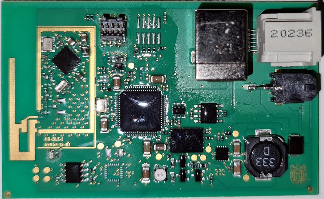
ZASHQ-BLE-1D
May 27, 2021Base Station Board with Bluetooth functionality
Equipment Class
DTS - Digital Transmission System