ZBTRH-750HANDLE REMOTE CONTROLLER
Moneual Inc.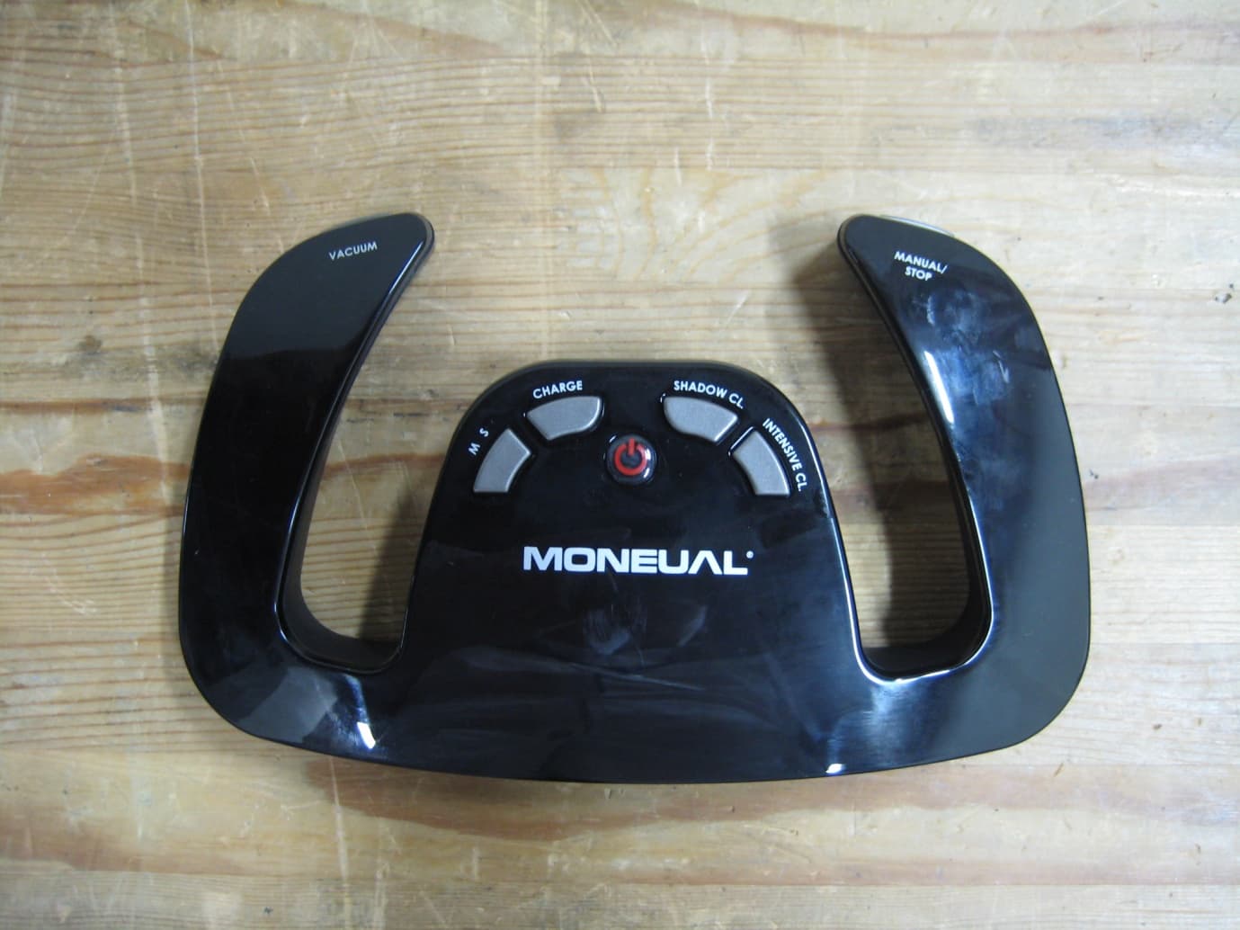
Click to zoom
Application Details
- Equipment Class
- DTS - Digital Transmission System
- Date of Grant
- Sep 19, 2012
- Application Purpose
- Original Equipment
- Date of Application
- Sep 19, 2012
- Equipment Note
- HANDLE REMOTE CONTROLLER
- Frequency Range
- 2403.00000000 - 2479.00000000
- Company
- Moneual Inc.
- Country
- South Korea
Documents & Files
Document Text
Text extracted from the exhibit documents filed with the FCC. Open a document above to read the original.
Users Manual
RH750 USER GUIDE User’s Manual Copyright ⓒ 2011 MONEUAL Inc. All rights reserved. The MONEUAL, MONCASO, MiNEW, RYDIS, SONAMU are trademarks, or registered trademarks of MONEUAL Inc. in the Republic of Korea and/or other counties. RH750 USER GUIDE RH750 USER GUIDE User’s Manual ENGLISH 4 RYDIS RH750 User’s Manual Table of Contents 1. Cautions for Safety 2. Components 3. Nomenclature 4. Operation 5. Troubleshooting 6. Specification 5 7 8 9 19 19 ENGLISH RYDIS RH750 User’s Manual 5 Meanings of caution icons It refers to important information, definitions, general knowledge and references. If you do not follow the instruction with this warning icon, a serious injury or property loss may occur. If you do not follow the instruction with this danger icon, a serious injury, death, or property loss may occur. Important Warning Danger Cautions for Safety The instructions with the following caution marks must be carefully read and followed in order to use the product properly and to prevent accident or damage which may occur during the operation of the product. ENGLISH 6 RYDIS RH750 User’s Manual Safety Instructions If you feel fatigue or have any trouble with hands or arms, manipulating the remote controller may worsen the symptom. Consult with a doctor before using the product. When you feel fatigue in your hands or arms during using the product, make sure to take a rest. If pain or discomfort is sustained, immediately stop using the product and consult a doctor. Do not throw or drop the product. When hit by a person or an object, accident, injury, damage or failure may be caused. If the product is wet with liquid such as water or beverage, remove the batteries and contract the service center. Using the product with the battery wet may cause product failure. Do not disassemble, revise or repair the product. Electric shock or failure may be caused. If anomalies such as unusual sound, smoke, smell, etc. are found, immediately remove the batteries and contact the service center. Never use the product at places (hospital, public organizations, etc.) where radio communication is prohibited. Radio Frequency may affect operation of devices. For a person equipped with a pacemaker, maintain the product more than 22 centimeters away from the pacemaker-mounted part. Radio Frequency may affect operation of the pacemaker. Do not leave the product in the middle of floor. A person may be injured by stumbling over it. Keep the product out of reach of children and do not place it at an unstable place. The product may fall off, resulting in injuries or failures. The Handle Remote Controller is composed of plastic and metal components. Burning the product may be dangerous. Discard the product in compliance with the applicable local recycling regulations. Do not use or store the product in a wet or dusty place. Product failure may be caused. Do not let the Handle Remote Controller make contact with a magnet. Operation error may be caused. When the Handle Remote Controller gets dirty, wipe it with soft cloth. Do not clean it with thinner, benzene, alcohol, etc. Surface damage may be caused. Do not use batteries other than the standard batteries. Product trouble or operation error may be caused. If you do not use the product for a long time, remove the batteries. Battery may be discharged over time. Do not use the product in a place exposed to flammable materials such as alcohol, gasoline, distillation materials, thinner, etc. or in a place where smoke, ashtray, candle light, stove, etc. are present. ENGLISH RYDIS RH750 User’s Manual 7 Components Handle Remote Controller 1 EA Handle Remote Controller holder 1 EA AA batteries 2 EA User’s Manual 1 Copy The appearance and specifications are subject to change without prior notice for better product functions or performance. Make sure to use expendables in standard. For inquires for appropriate standards, please ENGLISH 8 RYDIS RH750 User’s Manual Nomenclature 1. Power Button: Turns on or off the body of the robot cleaner. 2. Charging Button: Chargers the robot cleaner on the charger. 3. Under-bed Cleaning Button: Sets the robot cleaner to the under-bed cleaning mode. When you press the Power button, the charging can be cancelled. For details, see the manual on the robot cleaner. When you press the Manual/Stop button, the Under-bed cleaning will be cancelled and the robot cleaner will work in the Manual mode. For details, see the manual on the robot cleaner. When you press the Manual/Stop button, the Intensive cleaning will be cancelled and the robot cleaner will work in the Manual mode. When the motion function is activated, the green LED will be lit. Without any move for around ten seconds, in this state, the motion function will be automatically released. Once the motion play function is stopped, the red LED will be lit. If the robot cleaner remains unmoved for around five seconds, the red LED will be automatically turned off. 4. Intensive Cleaning Button: Sets the robot cleaner to the intensive cleaning mode at the current position. 5. Suction Button: Changes the suction force of the robot cleaner to Weak → Middle → Strong whenever the button is pressed. 6. Manual/Stop: Runs the robot cleaner in manual cleaning mode or stops the robot cleaner. 7. Motion Play Button: Activates the motion play function to run the robot cleaner using the internal motion sensor. Press this button again to disable the motion play function. ⑤ Suction Control Button ⑦ Motion Start Button ② Charging Button ③ Under-bed Cleaning Button ① Power Button ⑥ Manual/Stop ④ Intensive Cleaning Button Button Description ENGLISH RYDIS RH750 User’s Manual 9 Installing the batteries to the Handle Remote Controller Operation 1. Press the hook of the rear cover and open the cover. 2. Open the battery cover and insert the two AA batteries starting from the negative pole, as seen in the figure. 3. Close the battery cover. When rechargeable batteries are used, use rechargeable Ni-MH batteries. Do not use lithium …
Text truncated - open the document above for the full version.
Block Diagram
RH - 750 HANDLE REMOCON BLOCK DIAGRAM KEY SWITCH LED RH - 750 HANDLE REMOCON BLOCK DIAGRAM MAIN PROCESSOR 16MHz MAIN PROCESSOR (Internal Clock: 32MHz) 2.4GHz RF MODULE SENSOR I2C INTERFACE SPI INTERFACE LOGIC SIGNAL 8MHz BATTERY REVERSE LOW BATTERY DETECT MAIN PROCESSOR BATTERY REVERSE PROTECT RF MODULESENSOR LDO REGULATOR 1.5V ‘AA’ TYPE BATTERY *2 로봇가전사업부
Cover Letter(s)
Rev 11/20/07 Federal Communications Commission Authorization and Evaluation Division Confidentiality Request regarding application for certification of FCC ID: ZBTRH-750. Pursuant to Sections 0.457 and 0.459 of the Commission’s Rules, we hereby request confidential treatment of information accompanying this application as outlined below: Exhibit Type File Name Schematic Diagram Parts List RH-750_SchDia RH-750-PartsLst The above materials contain trade secrets and proprietary information not customarily released to the public. The public disclosure of these materials may be harmful to the applicant and provide unjustified benefits to its competitors. The applicant understands that pursuant to Section 0.457 of the Rules, disclosure of this application and all accompanying documentation will not be made before the date of the Grant for this application. Pursuant to DA04-1705 June 15, 2004 of the Commission’s public notice, we also request temporary confidential treatment of information accompanying this application as outlined below: Exhibit Type File Name External Photos Internal Photos RH-750_ExtPho RH-750-IntPho User Manual Test Setup Photos RH-750_UsrMan RH-750_SetupPho Your sincerely Name: Myeong-do, Moon Position: Sytem R&D Dept., Director Tel: 82-70-4170-8990 Fax: 82-2-866-8380 Email: [email protected]
ID Label/Location Info
ID Label/Location Information The following sentences are inserted at the end of page 6 on the user manual. “This device complies with part 15 of the FCC Rules. Operation is subject to the following two conditions: (1) This device may not cause harmful interference, and (2) this device must accept any interference received, including interference that may cause undesired operation. ”
Operational Description
Working specification of Handle Remote Controller 1. Working frequencies of remote control uses 2.4GHz ISM BAND and communicate with robot cleaner through 11 frequency channels as follows 2469MHz, 2425MHz, 2451MHz, 2464MHz, 2403MHz, 2430MHz, 2406MHz, 2422MHz, 2473MHz, 2455MHz, 2479MHz 2. 2 AA batteries are used to supply the power, which is connected to internal IC, and protected by battery power inversely inserted by “BATTERY REVERSE PROTECT.” 3. “MAIN PROCESSOR” receives key inputs by using MATRIX method and transmits outputs corresponding key inputs through “RF MODULE” 4. “SENSOR” ,that is acceleration sensor, reads sensor value according to level of tilting from “MAIN PROCESSOR” and transfer equivalent data as tilting through “RF MODULE” 5. “LOW BATTERY DETECT” is VOLTAGE DETECTOR that monitors battery voltage and informs voltage status of batteries to “MAIN PROCESSOR” 6. “DISPLAY” is LED screen that shows press status of keys pressed and RF transmitting status. Working specification of main body (robot cleaner) 1. Working frequencies of main body uses 2.4GHz ISM BAND and communicate with robot cleaner through 11 frequency channels as follows 2469MHz, 2425MHz, 2451MHz, 2464MHz, 2403MHz, 2430MHz, 2406MHz, 2422MHz, 2473MHz, 2455MHz, 2479MHz. 2. Robot cleaner basically performs certain patterns and mapping with operating wheel motors, brush motors, suction motor based on several sensor information according to internal SOFTWARE ALGORISM. 3. Data transmitted by “RF MODULE” is processed by “MAIN PROCESSOR” and each corresponding functions work and control and perform, by internal SOFTWARE ALGORISM, units as follows - DISPLAY - MOTOR POWER(ON/OFF) - SENSOR SIGNAL. - MOTORS (WHEEL, BRUSH, FAN) - ANALOG SIGNAL TO SPEAKER. - EXTERNAL FLASH MEMORY - CHARGER TO BATTERY 4. It uses LiFePO4(Lithium iron phosphate) battery as main power and is NORMAL VOLTAGE 12.8VDC, MAX VOALTAGE 14.6VDC 5. Through “5V DC-DC CONVERTER”, battery power is supplied to following internal circuit. - LOGIC IC - ENCODER - LED DISPLAY - SENSOR - AUDIO AMP’ & SPEAKER 6. 5V power is supplied to “3.3VDC LDO” and 3.3V power is supplied to following internal circuit. - MAIN PROCESSOR - LOGIC IC - KEY SWITCH - FLASH MEMORY - SENSOR - RF MODULE 7. Through “MOTOR POWER CONTROL”, battery power is supplied to motors (WHEEL, BRUSH, FAN ) 8. “MAIN POWER SWITCH” is physical switch and it can cut off or supply power to whole circuit by “MAIN POWER CONTROL” 9. External “18VDC ADAPTER” power is voltage for charging battery and charges at least 95% of battery capacity through “BATTERY CHARGE DRIVER” controlled by “MAIN PROCESSOR”. 10. FLASH MEMORY saves several status information and setting value of robot cleaner and additionally saves distinct PHYSICAL ADDRESS for synchronization (MATCHING) of remote control. 11. Internal motors (WHEEL, BRUSH, FAN) control RPM and speed according to PWM(Pulse Width Modulation) signal based on data processed by input signal like sensor value of MAIN PROCESSOR 12. Display has a 8x8 MATRIX structure from MAIN PROCESSOR and it is printed out in order for a short time. 13. “FRONT & BOTTOM OBSTACLE SENSOR” controls motors as internal algorithm judging if obstacle exists or not after getting signal reflected from obstacle, which pulse signal out of MAIN PROCESSOR changed to, through ADC(Analog to Digital Convertor) 14. “KEY SWITCH” is function to input signals regarding power ON/OFF(Display power and motors power), mode selection, start/stop to MAIN PROCESSOR
Test Report
IST Co., Ltd. TEST REPORT NO. : 12-IST-0537 1 of 28 IST(02) 029 A4 모(101025) The test result only responds to the tested sample. This report shall not be reproduced except in full, without the allowance of the test laboratory. CERTIFICATION TEST REPORT FCC CFR47 PART 15 SUBPART C Test Report File No. 12-IST-0537 ■ Basic □ Alternate Date of Receipt August 16, 2012 Begin of test date August 21, 2012 Date of Issue September 04, 2012 End of test date August 30, 2012 Kind of Product Handle Remote Controller Basic Model(s) RH-750 FCC ID ZBTRH-750 Applicant MONEUAL INC. Address 1501, 15 th FL. Partners Tower I, 83, Gasandigital1-ro, Geumcheon-gu, Seoul, Korea Manufacturer MONEUAL INC. Address 1501, 15 th FL. Partners Tower I, 83, Gasandigital1-ro, Geumcheon-gu, Seoul, Korea Test Result ■ Positive Negative Tested By Reviewed By B.O.KO S.J.CHO Comment(s) - Investigations requested : Measurement to the relevant clauses of FCC rules and regulations Part 15 Subpart C - The test report is consists of 28 pages - The test result only responds to the tested sample. - It is not allowed to copy this report even partly without the allowance of IST Co., Ltd. - This equipment as for has been shown to be capable of continued compliance with the applicable technical standards as indicated in the measurement report and was tested in accordance with the measurement procedures specified in ANSI C63.4 - I assume full responsibility for accuracy and completeness of these data. IST Co., Ltd. TEST REPORT NO. : 12-IST-0537 2 of 28 IST(02) 029 A4 모(101025) The test result only responds to the tested sample. This report shall not be reproduced except in full, without the allowance of the test laboratory. TABLE OF CONTENTS Table of contents 2 Information of test laboratory 3 Description of the Equipment uder Test 3 Measurement Uncertainty, 4 Summary of the test results 5 - Conducted Emission 6-8 - Radiated Emission 9-15 - Peak Power Output 16-17 - Band edge 18-23 - 6dB Bandwidth 24-25 - Power Density 26-27 - Antenna Requirements 28 IST Co., Ltd. TEST REPORT NO. : 12-IST-0537 3 of 28 IST(02) 029 A4 모(101025) The test result only responds to the tested sample. This report shall not be reproduced except in full, without the allowance of the test laboratory. INFORMATION OF TEST LABORATORY IST Co., Ltd. 400-19, Singal-dong, Giheung-gu, Yongin-si, Gyeonggi-do, 446-599, Korea TEL : +82 31 326 6700 FAX : +82 31 326 6797 KOLAS Testing No. : 118 RRA Designation No. : KR0018 FCC Registration No. : 400603 FCC(DoC) Registration No. : 801060 VCCI Member No. : 1739 Description of the Equipment under Test Handle Remote Controller Model RH-750 Dimension L 199mm x W 120mm x H 58mm Weight About 115g(Without battery) Power Consumption About 70mW Power Supply DC 3 V(AA alkaline batteries (LR6) 2EA) Radio Frequency 2.4GHz ISM BAND Signal Transmission Distance(RF) About 10meters (variable depending on environment) Sensor 3-axis acceleration sensor, 3-axis gyroscope Motion recognition Embedded digital motion processor Specification(s) FCC CFR47 PART 15 SUBPART C Number of Channel 11(2403~2479MHz) Note: All the testing were performed according to the procedures in FCC CFR47 PART 15 SUBPART C IST Co., Ltd. TEST REPORT NO. : 12-IST-0537 4 of 28 IST(02) 029 A4 모(101025) The test result only responds to the tested sample. This report shall not be reproduced except in full, without the allowance of the test laboratory. Measurement Uncertainty Calculations The measurement uncertainties stated were calculated in accordance with the requirements of NIST Technical Note 1297 and NIS 81 (1994). TYPE Contribution Probability Distribution Uncertainty Remark B AMN Impedance Triangular +2.6/-2.7 dB CISPR Voltage Division Factor normal(k=2) ±0.2 Attenuation : AMN to Receiver normal(k=2) ±0.1 Receiver(ESCI(S/N:100374)) Sine-Wave Voltage Accuracy normal(k=2) ±1.0 dB CISPR Pulse Amplitude Response Rectangular ±1.5 dB Pulse Repetition Rate Response Rectangular ±1.5 dB Mismatch AMN to Receiver U-Shaped +0.7/-0.8 dB CISPR Reading normal(k=1) ±0.1 Combined Standard Uncertainty normal ± 1.8 dB Expanded Uncertainty U normal(k=2) ± 3.6 dB 95 % U = -3.70 / +3.42 (k=2, 95.45% confidence level) T Y P E Contribution Probability Distribution Uncertainty Remark B Antenna AF factor Normal(k=2) ±0.56 CAL. AF frequency interpolation Rectangular ±0.30 dB CISPR AF height deviations Rectangular ±0.50 dB CISPR ±0.30 dB directivity difference Rectangular +1.0/-0.0 dB CISPR phase center location(3 m) phase center location(10 m) Rectangular ±1.0 dB ±0.30 dB CISPR Receiver Sine Wave Voltage Accuracy Normal(k=2) ±0.20 dB CAL. Pulse Amplitude Sensibility Normal(k=2) ±0.40 dB CAL. Pulse Frequency Response Normal(k=2) ±0.57 dB CAL. Random Noise Normal(k=2) ±0.35 dB CAL. Mismatch : Antenna – receiver U-Shaped +0.9/-1.0 dB CISPR Table height Normal(k=2) ±0.01 dB CISPR Separation distance(3 m ) Separation distance(10 m ) Rectangular ±0.30 dB ±0.10 dB CISPR Combined standard Uncertainty Normal ± 1.13 Expanded Uncertainty U Normal(k=2) ± 2.26 dB 95 % U = ±2.26 (k=2, 95% confidence level) IST Co., Ltd. TEST REPORT NO. : 12-IST-0537 5 of 28 IST(02) 029 A4 모(101025) The test result only responds to the tested sample. This report shall not be reproduced except in full, without the allowance of the test laboratory. SUMMARY ( 2403 MHz ~ 2479 MHz) Applied Standard : FCC CRF Part 15 Subpart C Standard Section Description result remark 15.207 AC Conducted Emission N/A Operating by Battery Power (AA Size) 15.209 Field Strength of Harmonics Pass Meet the requirements 15.247(b) Peak Power Output Pass Meet the requirements 15.247(d) Conducted Band Edges Pass Meet the requirements Conducted Spurious Emission Pass Meet the requirements Radiated Band Edges Pass Meet the requirements Radiated Spurious Emission Pass Meet the requirements 15.247(a)(2) 6dB Bandwidth Pass Meet the requirements 15.247(e) Power Spectral Density Pass Meet the requirements 15.203 & 15.247(b) Antenna requirement - Meet the requirements Ap…
Text truncated - open the document above for the full version.
Contact Information
Applicant
Myung-do Moon(Manager)
Test Firm
IST Co., LtdCho Sung Jung
Technical Specifications
| # | Rule Parts | Frequency Range | Power Output |
|---|---|---|---|
| 1 | 15C | 2.40 GHz - 2.48 GHz | 1.00 mW |
Other Applications from Moneual Inc.
ZBTMR6550
Jul 08, 2012Robot Cleaner
Equipment Class
DTS - Digital Transmission System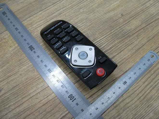
ZBTRC-750
May 26, 2011ROBOT CONTROL
Equipment Class
DXX - Part 15 Low Power Communication Device Transmitter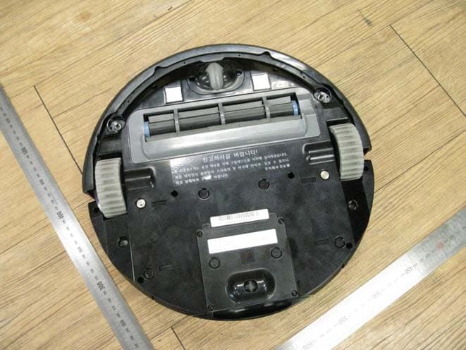
ZBTRYDISR750
May 25, 2011ROBOT CLEANER
Equipment Class
DXX - Part 15 Low Power Communication Device Transmitter