ZC4Z11Mobile Phone
Corporativo Lanix S.A. de C.V.
Click to zoom
Application Details
- Equipment Class
- PCE - PCS Licensed Transmitter held to ear
- Date of Grant
- Jun 05, 2011
- Application Purpose
- Original Equipment
- Date of Application
- Jun 05, 2011
- Equipment Note
- Mobile Phone
- Frequency Range
- 1850.20000000 - 1909.80000000
- Country
- Mexico
Documents & Files
Document Text
Text extracted from the exhibit documents filed with the FCC. Open a document above to read the original.
Users Manual
1 User Manual 2 Contents Attention and Precautions ------------------------------------------------ 6 FOR YOUR SAFETY................................................................... 6 SECURITY REQUIREMENTS ....................................................... 8 MAINTENANCE ....................................................................... 10 Your Phone ---------------------------------------------------------------- 13 Getting Started ------------------------------------------------------------ 18 BATTERY .............................................................................. 18 REMOVING AND INSTALLING BATTERY ...................................... 18 CONNECTING TO NETWORK .................................................... 22 INSERTING AND REMOVING SIM CARD ..................................... 23 INSERTING AND REMOVING MEMORY CARD .............................. 24 3 P OWER ON/OFF PHONE .......................................................... 25 PIN AND PUK ....................................................................... 26 PHONE LOCK ......................................................................... 27 LOCKING THE KEYPAD ........................................................... 27 CONNECTING TO NETWORK .................................................... 28 Basic Functions ----------------------------------------------------------- 30 MAKING A CALL ..................................................................... 30 MAKING DOMESTIC CALLS ...................................................... 30 DIALING EXTENSION NUMBER OF FIXED-LINE TELEPHONE .......... 31 DIALING INTERNATIONAL CALLS............................................... 31 DIALING PHONE NUMBERS IN THE CALL RECORDS ..................... 33 EMERGENCY CALLS ............................................................... 33 ANSWERING A CALL ............................................................... 34 CALL RECORDS ..................................................................... 35 CALL OPTIONS ....................................................................... 35 4 Using the menus ---------------------------------------------------------- 39 ACCESSING A MENU FUNCTION ............................................... 39 EXITING A MENU FUNCTION ..................................................... 39 LIST OF MENU FUNCTIONS ...................................................... 40 Messages ------------------------------------------------------------------ 42 CREATE A NEW SHORT MESSAGE ............................................ 42 CREATE A NEW MULTIMEDIA MESSAGE ................................... 42 BROADCAST MESSAGE ........................................................... 43 Contact ---------------------------------------------------------------------- 45 ADD NEW CONTACT ............................................................... 45 SEARCHING FOR A CONTACT .................................................. 45 Multimedia ------------------------------------------------------------------ 46 CAMERA ............................................................................... 46 AUDIO PLAYER ...................................................................... 46 VIDEO RECORDER ................................................................. 47 5 S OUND RECORDER ................................................................ 48 IMAGE VIEWER ...................................................................... 48 VIDEO PLAYER ...................................................................... 48 FM radio -------------------------------------------------------------------- 50 WAP ------------------------------------------------------------------------- 51 SETTING THE CONNECTION PROFILE ........................................ 51 SETTING THE WAP ................................................................ 52 Settings --------------------------------------------------------------------- 53 PRIVACY PROTECTION ........................................................... 53 Input method --------------------------------------------------------------- 54 ENTERING (ABC AND ABC) ..................................................... 54 ENTERING NUMBERS ............................................................. 54 ENTERING SYMBOLS .............................................................. 54 FCC Statement ----------------------------------------------------------- 55 6 Attention and Precautions For your safety Remember to comply with legal requirements and local restrictions when using the phone, for example, in aero plane, petrol stations, hospital or while driving Always keep your handsfree to operate the vehicle while driving. Your first consideration while driving should be road safety. Don’t use handset while driving. As per the law, phone should not be used at refueling point near fuel or chemicals. Mobile phones can interfere with the functioning of medical devices such as hearing aids or pacemakers. Keep at least 20 cm(9 inches) between the phone and pacemaker. 7 When using the mobile phone hold it to the ear which is furthest away from the pacemaker. For more information, consult your doctor. All wireless phones may be susceptible to interference, which could affect performance. The phone may cause interference in the vicinity of TV sets, radios and PCs. The mains voltage (V) specified on the power supply unit must not be exceeded. Otherwise the charging device may be damaged. The power supply must be plugged into an easily accessible AC mains power socket when charging the battery. The only way to turn off the charging device after charging the battery is to unplug it. Only qualified personnel may install or repair this 8 product. When connecting to any other product, read its user guide for detailed safety instructions. Do not connect incompatible products. Use only approved enhancements and batteries. Do not connect incompatible products. Security Requiremen…
Text truncated - open the document above for the full version.
ID Label/Location Info
Label & Label location
Internal Photos
Internal Photos
RF Exposure Info
NCL CALIBRATION LABORATORIES Calibration File No: DC-1201 Project Number: SPTB-ALSAS-5566 C E R T I F I C A T E OF C A L I B R A T I O N It is certified that the equipment identified below has been calibrated in the NCL CALIBRATION LABORATORIES by qualified personnel following recognized procedures and using transfer standards traceable to NRC/NIST. Validation Dipole 1900MHz Head & Body Manufacturer: APREL Laboratories Part number: ALS-D-1900-S-2 Frequency: 1900MHz Serial No: 210-00716 Customer: SPORTON Calibrated: 19 th February 2011 Released on: 25 h February 2011 NCL CALIBRATION LABORATORIES 303 Terry Fox Drive, Suite 102 Division of APREL Kanata, Ontario TEL: (613) 435-8300 CANADA K2K 3J1 FAX: (613) 435-8306 NCL Calibration Laboratories Division of APREL Inc. This page has been reviewed for content and attested to by signature within this document. Conditions Dipole 210-00716 was a new dipole taken from stock. Ambient Temperature of the Laboratory: 22 °C +/- 0.5°C Temperature of the Tissue: 21 °C +/- 0.5°C Primary Measurement Standards Instrument Serial Number Cal due date Power meter Anritsu MA2408A 190025437 Nov.4, 2010 Power Sensor Anritsu MA2481D 103555 Nov 4, 2010 Attenuator HP 8495A (70dB) 1944A10711 Sept. 14, 2010 Network Analyzer Anritsu MT8801C MB11855 Feb. 8, 2011 Secondary Measurement Standards Signal Generator Agilent E4438C -506 MY55182336 June 7, 2011 NCL Calibration Laboratories Division of APREL Inc. This page has been reviewed for content and attested to by signature within this document. 3 Calibration Results Summary The following results relate the Calibrated Dipole and should be used as a quick reference for the user. Mechanical Dimensions Length: 67.1 mm Height: 38.9 mm Electrical Specification 1900MHz Tissue Type Return Loss: Impedance: SWR: Head -30.471 50.426 1.064U Body -24.274 53.459 1.130U System Validation Results Tissue Frequency 1 Gram10 Gram Peak Head 1900 MHz 39.378 19.668 77.268 Body 1900 MHz 39.654 19.668 77.268 1900MHz NCL Calibration Laboratories Division of APREL Inc. This page has been reviewed for content and attested to by signature within this document. 4 Introduction This Calibration Report has been produced in line with the SSI Dipole Calibration Procedure SSI-TP-018-ALSAS. The results contained within this report are for Validation Dipole 210-00716. The calibration routine consisted of a three-step process. Step 1 was a mechanical verification of the dipole to ensure that it meets the mechanical specifications. Step 2 was an Electrical Calibration for the Validation Dipole, where the SWR, Impedance, and the Return loss were assessed. Step 3 involved a System Validation using the ALSAS-10U, along with APREL E-030 130 MHz to 26 GHz E-Field Probe Serial Number 215. References o IEEE Standard 1528 (2003) including Amendment 1 IEEE Recommended Practice for Determining the Peak Spatial-Average Specific Absorption Rate (SAR) in the Human Head from Wireless Communications Devices: Measurement Techniques o EN 62209-1 (2006) Human Exposure to RF Fields from hand-held and body-mounted wireless communication devices - Human models. instrumentation, and procedures-Part 1: Procedure to measure the Specific Absorption Rate (SAR) for hand-held mobile wireless devices o IEC 62209-2 Ed. 1.0 (2010-03) Human exposure to RF fields from hand-held and body-mounted wireless devices - Human models, instrumentation, and procedures - Part 2: specific absorption rate (SAR) for wireless communication devices (30 MHz - 6 GHz) o TP-D01-032-E020-V2 E-Field probe calibration procedure o D22-012-Tissue dielectric tissue calibration procedure o D28-002-Dipole procedure for validation of SAR system using a dipole o IEEE 1309 Draft Standard for Calibration of Electromagnetic Field Sensors and Probes, Excluding Antennas, from 9kHz to 40GHz Conditions Dipole 210-00716 was a new dipole taken from stock. Ambient Temperature of the Laboratory: 22 °C +/- 0.5°C Temperature of the Tissue: 20 °C +/- 0.5°C NCL Calibration Laboratories Division of APREL Inc. This page has been reviewed for content and attested to by signature within this document. 5 Electrical Calibration Electrical Specification 1900MHz Tissue Type Measured Epsilon Measured Sigma Head 38.12 1.41 Body 51.52 1.57 Head Tissue Body Tissue NCL Calibration Laboratories Division of APREL Inc. This page has been reviewed for content and attested to by signature within this document. 6 Electrical Specification 1900MHz Impedance Tissue Type Measured Epsilon Measured Sigma Head 38.12 1.41 Body 51.52 1.57 Head Tissue Body Tissue NCL Calibration Laboratories Division of APREL Inc. This page has been reviewed for content and attested to by signature within this document. 7 Electrical Specification 1900MHz Standing Wave Ratio Tissue Type Measured Epsilon Measured Sigma Head 38.12 1.41 Body 51.52 1.57 Head Tissue Body Tissue NCL Calibration Laboratories Division of APREL Inc. This page has been reviewed for content and attested to by signature within this document. 8 Test Equipment The test equipment used during Probe Calibration, manufacturer, model number and, current calibration status are listed and located on the main APREL server R:\NCL\Calibration Equipment\Instrument List May 2010.
RF Exposure Info
Report No: SH11050009S01 Page 3 of 90 TABLE OF CONTENT 1 GENERAL CONDITIONS ........................................................................................................................................ 5 2 ADMINISTRATIVE DATE ....................................................................................................................................... 6 2.1 IDENTIFICATION OF THE RESPONSIBLE TESTING LABORATORY ............................................................................. 6 2.2 IDENTIFICATION OF THE RESPONSIBLE TESTING LOCATION(S) .............................................................................. 6 2.3 ORGANIZATION ITEM ............................................................................................................................................ 6 2.4 IDENTIFICATION OF APPLICANT ............................................................................................................................. 6 3 EQUIPMENT UNDER TEST (EUT)........................................................................................................................ 7 4 OPERATIONAL CONDITIONS DURING TEST .................................................................................................. 8 4.1 SCHEMATIC TEST CONFIGURATION ....................................................................................................................... 8 4.2 SAR MEASUREMENT SYSTEM .............................................................................................................................. 8 4.2.1 Robot system specification ............................................................................................................................... 9 4.2.2 Probe Specification .......................................................................................................................................... 9 ISOTROPIC E-FIELD PROBE SPECIFICATION ...................................................................................................................... 11 BOUNDARY DETECTION UNIT AND PROBE MOUNTING DEVICE ....................................................................................... 11 DAQ-PAQ (ANALOG TO DIGITAL ELECTRONICS) .............................................................................................................. 12 4.2.3 Phantoms, Device Holder and Simulant Liquid ............................................................................................. 13 ALSAS UNIVERSAL WORKSTATION ................................................................................................................................ 14 UNIVERSAL DEVICE POSITIONER ..................................................................................................................................... 14 4.2.4 SAR measurement procedure ......................................................................................................................... 16 4.2.5 Validation Test Using Flat Phantom .............................................................................................................. 17 VALIDATION DIPOLES ...................................................................................................................................................... 18 Validation Result ........................................................................................................................................................ 19 4.2.6 Measurement Procedure ................................................................................................................................ 20 4.2.7 Description of Interpolation/Extrapolation Scheme ...................................................................................... 20 5 CHARACTERISTICS OF THE TEST .................................................................................................................. 21 5.1 APPLICABLE LIMIT REGULATIONS ...................................................................................................................... 21 5.2 APPLICABLE MEASUREMENT STANDARDS .......................................................................................................... 21 6 LABORATORY ENVIRONMENT ........................................................................................................................ 22 7 TEST RESULTS ....................................................................................................................................................... 23 7.1 EXPLAIN ............................................................................................................................................................. 23 7.2 DIELECTRIC PERFORMANCE ................................................................................................................................ 23 7.3 CONDUCTED POWER ........................................................................................................................................... 24 7.4 SUMMARY OF MEASUREMENT RESULTS(GSM/GPRS 850/1900) ....................................................................... 24 7.5 SUMMARY OF MEASUREMENT RESULTS (BLUETOOTH FUNCTION) ..................................................................... 26 7.6 CONCLUSION ...................................................................................................................................................... 28 8 MEASUREMENT UNCERTAINTIES .................................................................................................................. 29 9 MAIN TEST INSTRUMENTS ................................................................................................................................ 31 Report No: SH11050009S01 Page 4 of 90 ANNEX A- ACCREDITATION CERTIFICATE ........................................................................................................... 32 ANNEX B- TEST LAYOUT ....…
Text truncated - open the document above for the full version.
RF Exposure Info
NCL CALIBRATION LABORATORIES Calibration File No.: CP-1145 Client.: IAC C E R T I F I C A T E OF C A L I B R A T I O N It is certified that the equipment identified below has been calibrated in the NCL CALIBRATION LABORATORIES by qualified personnel following recognized procedures and using transfer standards traceable to NRC/NIST. Equipment: Miniature Isotropic RF Probe 835 MHz Manufacturer: APREL Laboratories Model No.: E-020 Serial No.: 273-B Body calibration Calibration Procedure: SSI/DRB-TP-D01-032-E020-V2 Project No: SGLB-IAC rep-E020-5538 Calibrated: 13 September 2010 Released on: 17 September 2010 NCL CALIBRATION LABORATORIES 17 Bentley Avenue Division of APREL Lab. NEPEAN, ONTARIO TEL: (613) 820-4988 CANADA K2E 6T7 FAX: (613) 820-4161 NCL Calibration Laboratories Division of APREL Laboratories. Page 2 of 10 This page has been reviewed for content and attested to on Page 2 of this document. Introduction This Calibration Report reproduces the results of the calibration performed in line with the SSI/DRB-TP-D01-032-E020-V2 E-Field Probe Calibration Procedure. The results contained within this report are for APREL E-Field Probe E-020 273-B. References SSI/DRB-TP-D01-032-E020-V2 E-Field Probe Calibration Procedure IEEE 1528 “Recommended Practice for Determining the Peak Spatial-Average Specific Absorption Rate (SAR) in the Human Body Due to Wireless Communications Devices: Experimental Techniques” SSI-TP-011 Tissue Calibration Procedure IEC 62209 “Human exposure to radio frequency fields from hand-held and body- mounted wireless communication devices – Human models, instrumentation, and procedures –Part 1 & 2: Procedure to determine the Specific Absorption Rate (SAR) for hand-held devices used in close proximity of the ear (frequency range of 300 MHz to 3 GHz)” IEEE 1309 Draft Standard for Calibration of Electromagnetic Field Sensors and Probes, Excluding Antennas, from 9kHz to 40GHz Conditions Probe 273-B was a new-calibration. Ambient Temperature of the Laboratory: 22 °C +/- 0.5°C Temperature of the Tissue: 21 °C +/- 0.5°C NCL Calibration Laboratories Division of APREL Laboratories. Page 3 of 10 This page has been reviewed for content and attested to on Page 2 of this document. Calibration Results Summary Probe Type: E-Field Probe E-020 Serial Number: 273-B Frequency: 835 MHz Sensor Offset: 1.56 mm Sensor Length: 2.5 mm Tip Enclosure: Ertalyte* Tip Diameter: <5 mm Tip Length: 60 mm Total Length: 290 mm *Resistive to recommended tissue recipes per IEEE-1528 Sensitivity in Air Channel X: 1.2 μV/(V/m) 2 Channel Y: 1.2 μV/(V/m) 2 Channel Z: 1.2 μV/(V/m) 2 Diode Compression Point: 95 mV NCL Calibration Laboratories Division of APREL Laboratories. Page 4 of 10 This page has been reviewed for content and attested to on Page 2 of this document. Sensitivity in Body Tissue Measured Frequency: 835 MHz Epsilon: 57.19 (+/-5%) Sigma: 0.94 S/m (+/-5%) ConvF Channel X: 6. Channel Y: 6. Channel Z: 6. Tissue sensitivity values were calculated using the load impedance of the APREL Laboratories Daq-Paq. Boundary Effect: Uncertainty resulting from the boundary effect is less than 2% for the distance between the tip of the probe and the tissue boundary, when less than 2.44mm. Spatial Resolution: The measured probe tip diameter is 5 mm (+/- 0.01 mm) and therefore meets the requirements of SSI/DRB-TP-D01-032 for spatial resolution. NCL Calibration Laboratories Division of APREL Laboratories. Page 5 of 10 This page has been reviewed for content and attested to on Page 2 of this document. Receiving Pattern 835 MHz (Air) 0 0.2 0.4 0.6 0.8 1 1.2 0 10 20 30 40 50 60 70 80 90 10 0 110 120 13 0 140 150 160 17 0 180 190 200 21 0 220 230 24 0 25 0 260 270 280 29 0 30 0 310 320 33 0 340 350 Receiving Pattern Probe s/n 273-B 835MHz Ch1Ch2Ch3Tot NCL Calibration Laboratories Division of APREL Laboratories. Page 6 of 10 This page has been reviewed for content and attested to on Page 2 of this document. Isotropy Error 835 MHz (Air) -10 -9 -8 -7 -6 -5 -4 -3 -2 -1 0 1 2 3 4 5 6 7 8 9 10 01 0020 03 00 E r r o r [ d B ] I sotropy Error Probe s/n 273-B 835MHz 0 0.1 0.2 0.3 0.4 0.5 0.6 0.7 0.8 01002003 00 V o l t a g e ( m V ) D e gree s ( x 10 ) Isotropy Plot Pr obe s/n 273-B 835MHz Ch1Ch2Ch3 Isotropicity in Tissue: 0.10 dB NCL Calibration Laboratories Division of APREL Laboratories. Page 7 of 10 This page has been reviewed for content and attested to on Page 2 of this document. Dynamic Range 0. 01 0. 1 1 10 100 1 000 10 000 1 .0 0 10. 00 1 00. 00 1, 000 .00 1 0, 000. 00 100 ,00 0. 00 1 ,00 0, 000 .00 10, 00 0,0 00. 00 V o l t a g e [ m i c r o V ] Elec tric Fie ld [(V/m)^2 ] Probe 273-B Dynam ic Range Un co mp en sa te d Co m p en sa te d NCL Calibration Laboratories Division of APREL Laboratories. Page 8 of 10 This page has been reviewed for content and attested to on Page 2 of this document. Video Bandwidth -6 -5 -4 -3 -2 -1 0 1 110100100010000 P r o b e o u t p u t l e v e l ( d B ) Frequency (Hz) Probe Frequency Characteristics Video Bandwidth at 500 Hz 1 dB Video Bandwidth at 1.02 KHz: 3 dB NCL Calibration Laboratories Division of APREL Laboratories. Page 9 of 10 This page has been reviewed for content and attested to on Page 2 of this document. Conversion Factor Uncertainty Assessment Frequency: 835MHz Epsilon: 57.19 (+/-5%) Sigma: 0.94 S/m (+/-5%) ConvF Channel X: 6. 7%(K=2) Channel Y: 6. 7%(K=2) Channel Z: 6. 7%(K=2) To minimize the uncertainty calculation all tissue sensitivity values were calculated using a load impedance of 5 MΩ. Boundary Effect: For a distance of 2.4mm the evaluated uncertainty (increase in the probe sensitivity) is less than 2%. NCL Calibration Laboratories Division of APREL Laboratories. Page 10 of 10 This page has been reviewed for content and attested to on Page 2 of this document. Test Equipment The test equipment used during Probe Calibration, manufacturer, model number and, current calibration status are listed and located on the main APREL server R:\NCL\Calibration Equipment\Instrument L…
Text truncated - open the document above for the full version.
RF Exposure Info
NCL CALIBRATION LABORATORIES Calibration File No.: CP-1150 Client.: IAC C E R T I F I C A T E OF C A L I B R A T I O N It is certified that the equipment identified below has been calibrated in the NCL CALIBRATION LABORATORIES by qualified personnel following recognized procedures and using transfer standards traceable to NRC/NIST. Equipment: Miniature Isotropic RF Probe 1900 MHz Manufacturer: APREL Laboratories Model No.: E-020 Serial No.: 273-B Calibration Procedure: SSI/DRB-TP-D01-032-E020-V2 Project No: SGLB-IAC rep-E020-5538 Calibrated: 13 September 2010 Released on: 17 September 2010 NCL CALIBRATION LABORATORIES 17 Bentley Avenue Division of APREL Lab. NEPEAN, ONTARIO TEL: (613) 820-4988 CANADA K2E 6T7 FAX: (613) 820-4161 NCL Calibration Laboratories Division of APREL Laboratories. Page 2 of 10 This page has been reviewed for content and attested to on Page 2 of this document. Introduction This Calibration Report reproduces the results of the calibration performed in line with the SSI/DRB-TP-D01-032-E020-V2 E-Field Probe Calibration Procedure. The results contained within this report are for APREL E-Field Probe E-020 273-B. References SSI/DRB-TP-D01-032-E020-V2 E-Field Probe Calibration Procedure IEEE 1528 “Recommended Practice for Determining the Peak Spatial-Average Specific Absorption Rate (SAR) in the Human Body Due to Wireless Communications Devices: Experimental Techniques” SSI-TP-011 Tissue Calibration Procedure IEC 62209 “Human exposure to radio frequency fields from hand-held and body- mounted wireless communication devices – Human models, instrumentation, and procedures –Part 1 & 2: Procedure to determine the Specific Absorption Rate (SAR) for hand-held devices used in close proximity of the ear (frequency range of 300 MHz to 3 GHz)” IEEE 1309 Draft Standard for Calibration of Electromagnetic Field Sensors and Probes, Excluding Antennas, from 9kHz to 40GHz Conditions Probe 273-B was a new-calibration. Ambient Temperature of the Laboratory: 22 °C +/- 0.5°C Temperature of the Tissue: 21 °C +/- 0.5°C NCL Calibration Laboratories Division of APREL Laboratories. Page 3 of 10 This page has been reviewed for content and attested to on Page 2 of this document. Calibration Results Summary Probe Type: E-Field Probe E-020 Serial Number: 273-B Frequency: 1900 MHz Sensor Offset: 1.56 mm Sensor Length: 2.5 mm Tip Enclosure: Ertalyte* Tip Diameter: <5 mm Tip Length: 60 mm Total Length: 290 mm *Resistive to recommended tissue recipes per IEEE-1528 Sensitivity in Air Channel X: 1.3 μV/(V/m) 2 Channel Y: 1.3 μV/(V/m) 2 Channel Z: 1.3 μV/(V/m) 2 Diode Compression Point: 95 mV NCL Calibration Laboratories Division of APREL Laboratories. Page 4 of 10 This page has been reviewed for content and attested to on Page 2 of this document. Sensitivity in Head Tissue Measured Frequency: 1900 MHz Epsilon: 38.09 (+/-5%) Sigma: 1.38 S/m (+/-5%) ConvF Channel X: 4.9 Channel Y: 4.9 Channel Z: 4.9 Tissue sensitivity values were calculated using the load impedance of the APREL Laboratories Daq-Paq. Boundary Effect: Uncertainty resulting from the boundary effect is less than 2% for the distance between the tip of the probe and the tissue boundary, when less than 2.44mm. Spatial Resolution: The measured probe tip diameter is 5 mm (+/- 0.01 mm) and therefore meets the requirements of SSI/DRB-TP-D01-032 for spatial resolution. NCL Calibration Laboratories Division of APREL Laboratories. Page 5 of 10 This page has been reviewed for content and attested to on Page 2 of this document. Receiving Pattern 1900 MHz (Air) 0 0.2 0.4 0.6 0.8 1 1.2 0 10 20 30 40 50 60 70 80 90 10 0 110 120 13 0 140 150 160 17 0 180 190 200 21 0 220 230 24 0 25 0 260 270 280 29 0 30 0 310 320 33 0 340 350 Receiving Pattern Probe s/n 273-B 1900MHz Ch1Ch2Ch3Tot NCL Calibration Laboratories Division of APREL Laboratories. Page 6 of 10 This page has been reviewed for content and attested to on Page 2 of this document. Isotropy Error 1900 MHz (Air) -10 -9 -8 -7 -6 -5 -4 -3 -2 -1 0 1 2 3 4 5 6 7 8 9 10 0100200300 E r r o r [ d B ] Isotropy Err or P robe s/n 27 3- B 19 00 M Hz 0 0. 1 0. 2 0. 3 0. 4 0. 5 0. 6 0. 7 0. 8 01 00200300 V o l t a g e ( m V ) D egr ees (x10 ) Isotropy Plot Probe s/n 273-B 1900MHz Ch 1Ch2 Ch 3 Isotropicity: 0.10 dB NCL Calibration Laboratories Division of APREL Laboratories. Page 7 of 10 This page has been reviewed for content and attested to on Page 2 of this document. Dynamic Range 0. 01 0. 1 1 10 100 1 000 10 000 1 .0 0 10. 00 1 00. 00 1, 000 .00 1 0, 000. 00 100 ,00 0. 00 1 ,00 0, 000 .00 10, 00 0,0 00. 00 V o l t a g e [ m i c r o V ] Elec tric Fie ld [(V/m)^2 ] Probe 273-B Dynam ic Range Un co mp en sa te d Co m p en sa te d NCL Calibration Laboratories Division of APREL Laboratories. Page 8 of 10 This page has been reviewed for content and attested to on Page 2 of this document. Video Bandwidth -6 -5 -4 -3 -2 -1 0 1 110100100010000 P r o b e o u t p u t l e v e l ( d B ) Frequency (Hz) Probe Frequency Characteristics Video Bandwidth at 500 Hz 1 dB Video Bandwidth at 1.02 KHz: 3 dB NCL Calibration Laboratories Division of APREL Laboratories. Page 9 of 10 This page has been reviewed for content and attested to on Page 2 of this document. Conversion Factor Uncertainty Assessment Frequency: 1900MHz Epsilon: 38.09 (+/-5%) Sigma: 1.38 S/m (+/-5%) ConvF Channel X: 4.9 7%(K=2) Channel Y: 4.9 7%(K=2) Channel Z: 4.9 7%(K=2) To minimize the uncertainty calculation all tissue sensitivity values were calculated using a load impedance of 5 MΩ. Boundary Effect: For a distance of 2.4mm the evaluated uncertainty (increase in the probe sensitivity) is less than 2%. NCL Calibration Laboratories Division of APREL Laboratories. Page 10 of 10 This page has been reviewed for content and attested to on Page 2 of this document. Test Equipment The test equipment used during Probe Calibration, manufacturer, model number and, current calibration status are listed and located on the main APREL server R:\NCL\Calibration Equipment\Instrument Lis…
Text truncated - open the document above for the full version.
RF Exposure Info
NCL CALIBRATION LABORATORIES Calibration File No.: CP-1151 Client.: IAC C E R T I F I C A T E OF C A L I B R A T I O N It is certified that the equipment identified below has been calibrated in the NCL CALIBRATION LABORATORIES by qualified personnel following recognized procedures and using transfer standards traceable to NRC/NIST. Equipment: Miniature Isotropic RF Probe 1900 MHz Manufacturer: APREL Laboratories Model No.: E-020 Serial No.: 273-B Body Calibration Calibration Procedure: SSI/DRB-TP-D01-032-E020-V2 Project No: SGLB-IAC rep-E020-5538 Calibrated: 13 September 2010 Released on: 17 September 2010 NCL CALIBRATION LABORATORIES 17 Bentley Avenue Division of APREL Lab. NEPEAN, ONTARIO TEL: (613) 820-4988 CANA…
Text truncated - open the document above for the full version.
Contact Information
Applicant
Max Gaxiola(Product Manager)
Test Firm
Shanghai Morlab Communications Technology Co.,Ltdzhang jun
Technical Specifications
| # | Rule Parts | Frequency Range | Power Output | Emission | Tolerance |
|---|---|---|---|---|---|
| 2 | 24E | 1.85 GHz - 1.91 GHz | 336.00 mW | 250GXW | 2.5 ppm |
Other Applications from Corporativo Lanix S.A. de C.V.
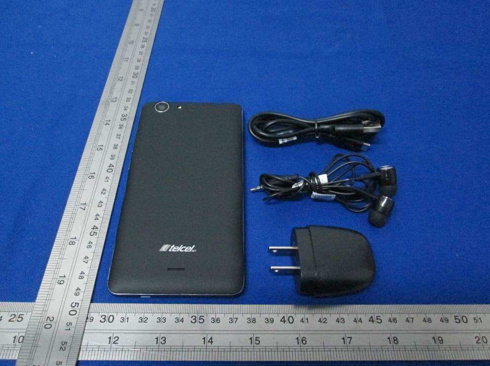
ZC4L1050
Jan 26, 2016smartphone
Equipment Class
DTS - Digital Transmission System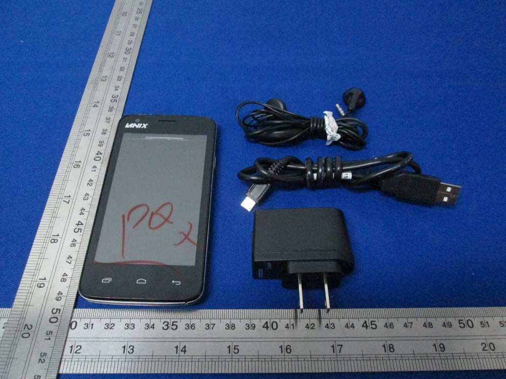
ZC4X250
Dec 07, 2015Smart Phone
Equipment Class
DSS - Part 15 Spread Spectrum Transmitter
ZC4X500B
Sep 29, 2015Smartphone
Equipment Class
PCE - PCS Licensed Transmitter held to ear
ZC4U100
Jul 25, 2015U100 Mobile Phone
Equipment Class
PCE - PCS Licensed Transmitter held to ear
ZC4LT500
Jul 20, 2015Smartphone
Equipment Class
DSS - Part 15 Spread Spectrum Transmitter