ZDEF414.0 MP Wireless Floodlight Camera
ShenZhen Foscam Intelligent Technology Co., Ltd.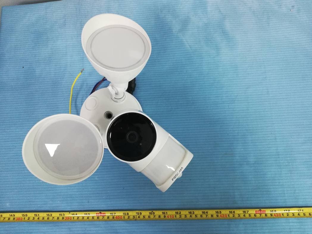
Click to zoom
Application Details
- Equipment Class
- NII - Unlicensed National Information Infrastructure TX
- Date of Grant
- Feb 02, 2021
- Application Purpose
- Original Equipment
- Date of Application
- Feb 02, 2021
- Equipment Note
- 4.0 MP Wireless Floodlight Camera
- Frequency Range
- 5745.00000000 - 5825.00000000
- Country
- China
Documents & Files
Document Text
Text extracted from the exhibit documents filed with the FCC. Open a document above to read the original.
Users Manual
V1.0 305503000573 Support email: [email protected] Quick Setup Guide 2 3 4 5 6 11 9 8 7 10 Floodlight Camera Installation Example Diagram Front Panel: Rear Panel: (Active) (Neutral) (Earth) Bkack White Green/Yellow Floodlight wiring Reset Speaker Micro SD Card Slot Foam Gasket Floodlight Microphone LED Indicator Lens Passive Infrared (PIR) Adiustment Knob Cap Screw Locking Nut Junction Box Wire nut Locking Collar Washer Add Device: Connection via the Foscam App (Recommended) Before You Get Started Scan the QR code below to download and install the Foscam APP. It is strongly recommended that you complete the "add devices" process on the Foscam app before the Floodlight hardware is installed. 1. Plug in the power and wait for a few seconds until hearing the “Ready for WiFi con guration”. WiFi connection Con rm WiFi connection WiFi 2. Make sure that your smart phone is connected to your WiFi router. xxxxx_2.4G xxxxx_5G Tips: If you didn’t hear the voice prompt, open the port cover on the back of the camera. Press and hold the Reset button for about 10 seconds to reset the camera. Input AC 100 ~ 240V Tips: The camera supports dual-band 2.4GHz and 5GHz WiFi networks, so you can choose the channel with the stronger signal to use. For example, choose your SSID: XXXXX_2.4G or XXXXX_5G. 3. Open the foscam APP and please sign up for a Foscam account, or sign in if you have one already. 4. After logging into Foscam APP, select “Tap to add a camera” or "+" icon on the upper right corner, then select "Scan the QR code" and scan the QR code that labeled at the bottom of your camera. Scan the QR code, located at the bottom of your camera Tap + icon Select ”Scan the QR code” Tap to add a camera Add Device < Scan the QR code Search in LAN Manually add Scan QR Code < Model: XXX MAC ID:000000000000 Username(default):admin Password(default):(blank) DDNS:XXXXXX. myfoscam.org FCC ID:XXXXX IC:12558A-XX S/N:FIAI1403000001 UID:XXXXXXXXXXX FHD Wireless IP Camera 5. In “Add Device”, if you hear "Hello Foscam", select the checkbox and tap ”Next”, continue to con rm that the device is in the blue fashing state and tap ”Next”. In “WiFi connection”, enter your WiFi's password and tap "Con rm", (see illustrations on next page). Tap + icon Con rm device ashes blue I have heard “Hello Foscam” Add Device Next Power the device on until the device voice prompts "Hella foscam" < Device flashes blue Add Device Next Con rm that the device is in the blue ashing state Wi-Fi connection The device will added by scanning the QR code and sound waves. Foscam_5G < 2.4GHz / 5.0GHz WiFi Password Con rm Enter your WiFi's password and tap "Con rm" 6. Please scan the QR code on the phone screen with the camera, then you will hear a voice prompt say ”WiFi connecting”Select the checkbox and tap ”Next”. Place the QR code directly in front of the camera For WiFi configuration, please point the QR code to the camera directly. WiFi connection < I have heard the voice prompt “WiFi connecting” Next Tick the checkbox and tap “Next” 10~15cm 3.94~5.9in Tips: Please place the QR code on the phone screen about 10 to 15cm (3.94 to 5.9in) away, and if you encounter di culties you can try to move the screen slowly around 10 – 15cm (3.94 - 5.9in). Note: If the process of adding a camera fails, please reset your camera and try adding again according to the above method. Open the port cover on the back of the camera. Press and hold the Reset button for 10 seconds. Set name Save Camera added successfully Please set the camera name: My Camera Camera added successfully and the name has been set 7. Wait a few seconds until the camera noti es you that the “Wireless connection succeeded”, which means your camera has connected to your WiFi successfully. After, you can set the camera name and tap “Save” in "Set name" interface. Reset Getting Started Note: Make sure you have installed the Foscam App, and have scanned the camera QR code and completed the "add device" process in the app before beginning the hardware installation process. This unit is designed to be mounted on a standard wiring junction box and requires connection to a 100 ~ 240VAC power supply. For optimum results, it is suggested that the installation height of the product should be 8.2ft (2.5m) and the camera should be tilted 15° downward. 1. Shut power o at the breaker in your house. Switch on/o the lights to make sure the electricity in your house is properly shut o . OFF Note: Risk of shock, disconnect power before servicing. Contains no user serviceable parts. This product must be installed by a licensed electrician in some countries. Check local regulations. Floodlight Installation To ensure a smoother video experience on your smart phone, it is recommended that your smart phone meet the following speci cations: iOS: version 11 or higher. Android: 4.1 or higher, using a device with a Graphics Processing Unit (GPU). Note: For the best experience, please update the APP to the latest version! On the front wall: Move towards or leave vertically Move horizontally Increased detection range for vertical movement up to 26ft (8m) Increased detection range for horizontal movement up to 33ft (10m) On the side wall: Move towards or leave vertically Move horizontally Detection range for vertical movement up to 20ft (6m) Detection range for horizontal movement up to 26ft (8m) 12 13 2. Access the area you want to be lit and the area you need camera coverage, and install your Floodlight Camera on the front wall or on the side wall. The side wall is highly recommended to get an optimal coverage for the oodlight and camera. * The motion sensor is more sensitive to the movements across the camera eld of view than movements towards or away from the sensor. We highly recommend you install the oodlight camera on the side wall. . 264 For the best product experience, we suggested installation height of Spotlight camera: 2.5m (8.2 feet), camera downward tilt angle 15°. 15° ۲٫٥m (۸٫۲ feet) 8. Tapping on the play …
Text truncated - open the document above for the full version.
Attestation Statements
ShenZhen Foscam Intelligent Technology Co., Ltd. Address: Room 901, Unit B, Building 7, Xingke 1st Stree, Vanke Cloud City Phase 1, Nanshan Dist., Shenzhen, China Tel: 0755-26745668-8230 Email: [email protected] Date: 2021-01-11 FEDERAL COMMUNICATIONS COMMISSIONS Authorization and Evaluation Division 7435 Oakland Mills Road Columbia, MD 21046 Dear Sir/Madam, The Main chip, model: RTL8822CS, installed in our product 4.0MP Wireless Floodlight Camera, model: F41, FCC ID: ZDEF41, this chip supports 2.4G Wi-Fi, 5G Wi-Fi (5150~5250MHz, 5250~5350MHz, 5470~5725MHz, 5725~5850MHz ) and Bluetooth function, but for marketing purpose, the Bluetooth and 5G Wi-Fi (5150~5250MHz, 5250~5350MHz, 5470~5725MHz) were disabled to use by manufacture in the software, the end user has no capability to activate it. Signature: David Tu Manager
Cover Letter(s)
ShenZhen Foscam Intelligent Technology Co., Ltd. Address: Room 901, Unit B, Building 7, Xingke 1st Street, Vanke Cloud City Phase 1, Nanshan Dist., Shenzhen, China Email: [email protected] Tel: 0755-26745668-8230 Pr oduct Similar ity Declar ation Date: 2020-11-17 To: Bay Area Compliance Laboratories Corp. 1274 Anvilwood Avenue Sunnyvale, CA 94089 Dear Sir/Madam, We, ShenZhen Foscam Intelligent Technology Co., Ltd., hereby declare that we have a product named as 4.0MP Wireless Floodlight Camera, (model: F41, FCC ID: ZDEF41) was tested by BACL, Meanwhile, for our marketing purpose, we would like to list a series model (FLC、FLC1、FLC2、FLC3、F21、F22、F42、F43、F44、F45、MFS4010、MFS4011、 MFS4012、MFS4013) on reports and certificate, all the models are identical in schematics. Only the model name is different. No other changes are made on them. We confirm that all information above is true, and we’ll be responsible for all the consequences. Please contact me if you have any question. Sincerely, Signature: Printed Name: David Tu Title: Manager
External Photos
Bay Area Compliance Laboratories Corp. (Shenzhen) Project No.: RSZ201104010-RF Page 1 of 3 EXHIBIT B - EUT EXTERNAL PHOTOGRAPHS Bay Area Compliance Laboratories Corp. (Shenzhen) Project No.: RSZ201104010-RF Page 2 of 3 Bay Area Compliance Laboratories Corp. (Shenzhen) Project No.: RSZ201104010-RF Page 3 of 3
ID Label/Location Info
Bay Area Compliance Laboratories Corp. (Shenzhen) Project No.: RSZ201104010-RF EXHIBIT A - FCC ID LABEL AND LOCATION FCC ID Label FCC ID Label Location Information The label shown shall be permanently affixed at a conspicuous location on the device and be readily visible to the user at the time purchase (Labeling requirements per 2.925)
Internal Photos
Bay Area Compliance Laboratories Corp. (Shenzhen) Project No.: RSZ201104010-RF Page 1 of 16 EXHIBIT C - EUT INTERNAL PHOTOGRAPHS Bay Area Compliance Laboratories Corp. (Shenzhen) Project No.: RSZ201104010-RF Page 2 of 16 Bay Area Compliance Laboratories Corp. (Shenzhen) Project No.: RSZ201104010-RF Page 3 of 16 Bay Area Compliance Laboratories Corp. (Shenzhen) Project No.: RSZ201104010-RF Page 4 of 16 Bay Area Compliance Laboratories Corp. (Shenzhen) Project No.: RSZ201104010-RF Page 5 of 16 Bay Area Compliance Laboratories Corp. (Shenzhen) Project No.: RSZ201104010-RF Page 6 of 16 Bay Area Compliance Laboratories Corp. (Shenzhen) Project No.: RSZ201104010-RF Page 7 of 16 Bay Area Compliance Laboratories Corp. (Shenzhen) Project No.: RSZ201104010-RF Page 8 of 16 WIFI ANT 2 Bay Area Compliance Laboratories Corp. (Shenzhen) Project No.: RSZ201104010-RF Page 9 of 16 WIFI ANT 1 Bay Area Compliance Laboratories Corp. (Shenzhen) Project No.: RSZ201104010-RF Page 10 of 16 Bay Area Compliance Laboratories Corp. (Shenzhen) Project No.: RSZ201104010-RF Page 11 of 16 Bay Area Compliance Laboratories Corp. (Shenzhen) Project No.: RSZ201104010-RF Page 12 of 16 Bay Area Compliance Laboratories Corp. (Shenzhen) Project No.: RSZ201104010-RF Page 13 of 16 Bay Area Compliance Laboratories Corp. (Shenzhen) Project No.: RSZ201104010-RF Page 14 of 16 Bay Area Compliance Laboratories Corp. (Shenzhen) Project No.: RSZ201104010-RF Page 15 of 16 Bay Area Compliance Laboratories Corp. (Shenzhen) Project No.: RSZ201104010-RF Page 16 of 16
RF Exposure Info
Bay Area Compliance Laboratories Corp. (Shenzhen) Report No.: RSZ201104010-00B FCC Part 15.407 Page 10 of 73 §1.1307 (B) (1) & §2.1091- MAXIMUM PERMISSIBLE EXPOSURE (MPE) Applicable Standard According to subpart 1.1307 (b)(1), 2.1091 systems operating under the provisions of this section shall be operated in a manner that ensures the public is not exposed to RF energy level in excess of the communication guidelines. Limits for General Population/Uncontrolled Exposure Limits for General Population/Uncontrolled Exposure Frequency Range (MHz) Electric Field Strength (V/m) Magnetic Field Strength (A/m) Power Density (mW/cm 2 ) Averaging Time (Minutes) 0.3-1.34 614 1.63 *(100) 30 1.34-30 824/f 2.19/f *(180/f 2 ) 30 30-300 27.5 0.073 0.2 30 300-1500 / / f/1500 30 1500-100,000 / / 1.0 30 f = frequency in MHz * = Plane-wave equivalent power density Result Calculated Formulary: Predication of MPE limit at a given distance S = 2 4R PG π S = power density (in appropriate units, e.g. mW/cm 2 ) P = power input to the antenna (in appropriate units, e.g., mW). G = power gain of the antenna in the direction of interest relative to an isotropic radiator, the power gain factor, is normally numeric gain. R = distance to the center of radiation of the antenna (appropriate units, e.g., cm) Frequency (MHz) Antenna Gain Tune up conducted power Evaluation Distance (cm) Power Density (mW/cm 2 ) MPE Limit (mW/cm 2 ) (dBi) (numeric) (dBm) (mW) 5725-5850 2 1.58 12.5 17.78 20 0.0056 1 Note: the 2.4G Wi-Fi cannot transmit at the same time with the 5G Wi-Fi. To maintain compliance with the FCC’s RF exposure guidelines, place the equipment at least 20cm from nearby persons. Result: Compliance
Test Report
This report may contain data that are not covered by the A2LA accreditation and are marked with an asterisk “★”. BACL is not responsible for the authenticity of any test data provided by the applicant. Data included from the applicant that may affect test results are marked with an asterisk ’*’. Customer model name, addresses, names, trademarks etc. are not considered data. This report cannot be reproduced except in full, without prior written approval of the Company. Unless otherwise stated the results shown in this test report refer only to the sample(s) tested. This report is valid only with a valid digital signature. The digital signature may be available only under the Adobe software above version 7.0. FCC PART 15.407 TEST REPORT For ShenZhen Foscam Intelligent Technology Co., Ltd. Room 901,Unit B,Building 7,Xingke 1st Street,Vanke Cloud City Phase 1,Nanshan Dist., Shenzhen,China FCC ID: ZDEF41 Report Type: Original Report Product Type: 4.0MP Wireless Floodlight Camera Re port Number: RSZ201104010-00B Re port Date: 2021-02-01 Reviewed B y: Jacob Kong RF Engineer Prepared By: Bay Area Compliance Laboratories Corp. (Shenzhen) 6/F., West Wing, Third Phase of Wanli Industrial Building, Shihua Road, Futian Free Trade Zone, Shenzhen, Guangdong, China Tel: +86-755-33320018 Fax: +86-755-33320008 www.baclcorp.com.cn Bay Area Compliance Laboratories Corp. (Shenzhen) Report No.: RSZ201104010-00B FCC Part 15.407 Page 2 of 71 TABLE OF CONTENTS GENERAL INFORMATION ....................................................................................................................................... 4 PRODUCT DESCRIPTION FOR EQUIPMENT UNDER TEST (EUT) ..................................................................................... 4 OBJECTIVE ................................................................................................................................................................... 4 TEST METHODOLOGY .................................................................................................................................................. 4 MEASUREMENT UNCERTAINTY .................................................................................................................................... 5 TEST FACILITY ............................................................................................................................................................. 5 SYSTEM TEST CONFIGURATION .......................................................................................................................... 6 DESCRIPTION OF TEST CONFIGURATION ...................................................................................................................... 6 EUT EXERCISE SOFTWARE .......................................................................................................................................... 6 DUTY CYCLE: ............................................................................................................................................................... 6 EQUIPMENT MODIFICATIONS ....................................................................................................................................... 6 SUPPORT EQUIPMENT LIST AND DETAILS .................................................................................................................... 6 EXTERNAL I/O CABLE .................................................................................................................................................. 6 BLOCK DIAGRAM OF TEST SETUP ................................................................................................................................ 7 SUMMARY OF TEST RESULTS ............................................................................................................................... 8 TEST EQUIPMENT LIST ........................................................................................................................................... 9 §1.1307 (B) (1) & §2.1091- MAXIMUM PERMISSIBLE EXPOSURE (MPE) ..................................................... 10 APPLICABLE STANDARD ............................................................................................................................................ 10 RESULT ...................................................................................................................................................................... 10 FCC §15.203 – ANTENNA REQUIREMENT .......................................................................................................... 11 APPLICABLE STANDARD ............................................................................................................................................ 11 ANTENNA CONNECTOR CONSTRUCTION .................................................................................................................... 11 FCC §15.407 (b) (6) §15.207 (a) – CONDUCTED EMISSIONS ............................................................................. 12 APPLICABLE STANDARD ............................................................................................................................................ 12 EUT SETUP ................................................................................................................................................................ 12 EMI TEST RECEIVER SETUP ....................................................................................................................................... 12 TEST PROCEDURE ...................................................................................................................................................... 12 TEST RESULTS SUMMARY .......................................................................................................................................... 13 TEST DATA .....................................................................…
Text truncated - open the document above for the full version.
Test Setup Photos
Bay Area Compliance Laboratories Corp. (Shenzhen) Project No.: RSZ201104010-RF Page 1 of 2 EXHIBIT D - TEST SETUP PHOTOGRAPHS Conducted Emissions - Front View Conducted Emissions - Side View Bay Area Compliance Laboratories Corp. (Shenzhen) Project No.: RSZ201104010-RF Page 2 of 2 Radiated Emissions View (Below 1 GHz) Radiated Emissions View (Above 1 GHz)
Contact Information
Applicant
Yongkun Qi
Test Firm
Bay Area Compliance Laboratories Corp. (Shenzhen)Well Wang
[email protected]+86 (0) 755 33320018
Technical Specifications
| # | Rule Parts | Frequency Range | Power Output |
|---|---|---|---|
| 1 | 15E | 5.75 GHz - 5.83 GHz | 16.00 mW |
Other Applications from ShenZhen Foscam Intelligent Technology Co., Ltd.
ZDEC8M
Jul 01, 2026Wireless IP Camera
Equipment Class
DTS - Digital Transmission System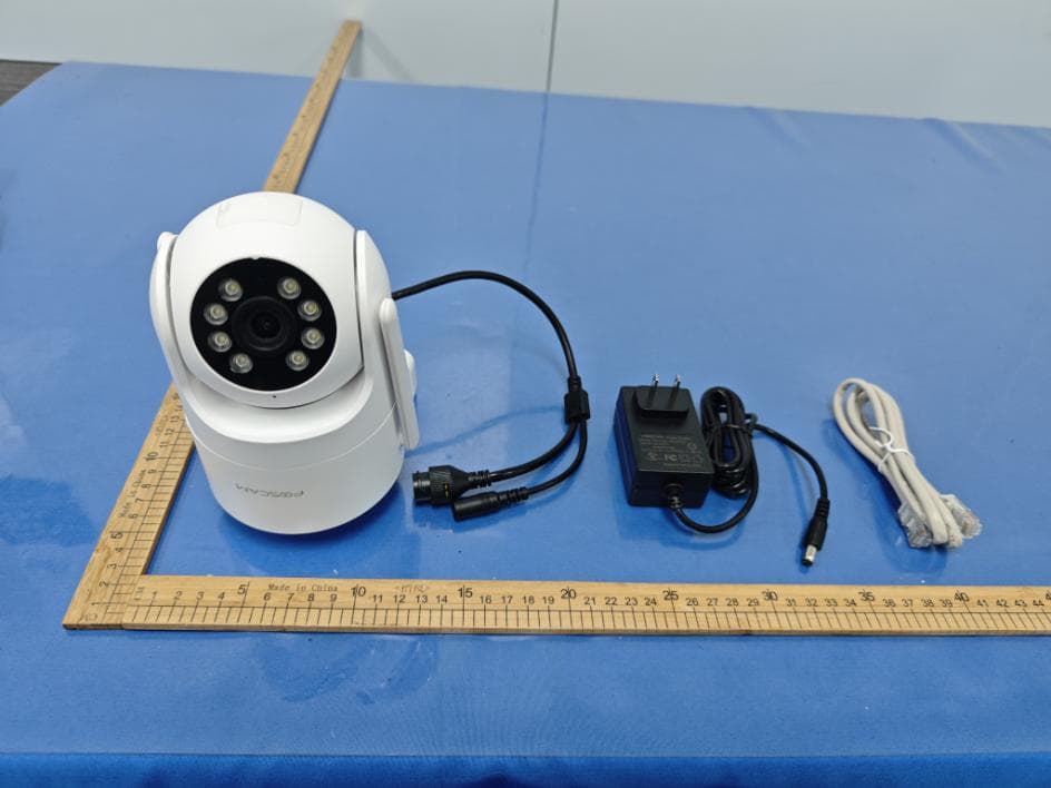
ZDEPD8
Mar 02, 2026Wireless IP Camera
Equipment Class
NII - Unlicensed National Information Infrastructure TX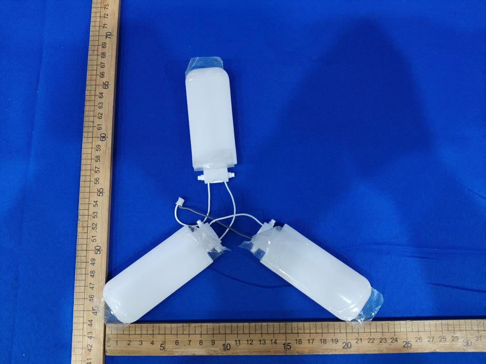
ZDELB5
Jan 14, 2026Wi-Fi IP Camera
Equipment Class
DTS - Digital Transmission System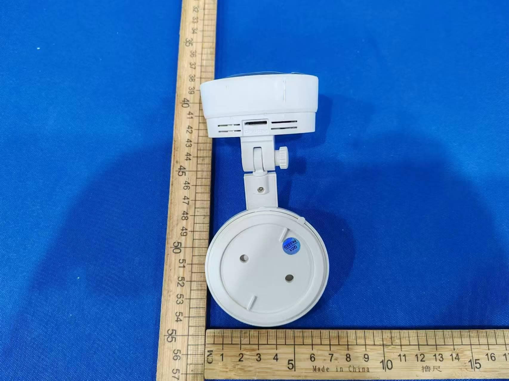
ZDEC5M
Oct 14, 2024Wireless IP Camera
Equipment Class
NII - Unlicensed National Information Infrastructure TX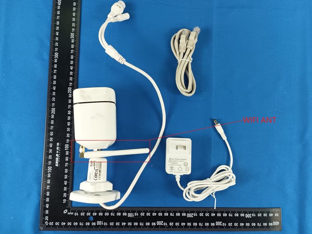
ZDEV5P
Sep 04, 2023QHD WiFi IP Camera
Equipment Class
NII - Unlicensed National Information Infrastructure TX