ZERNSM01NFC Smartcard Module (NSM01)
Access Ltd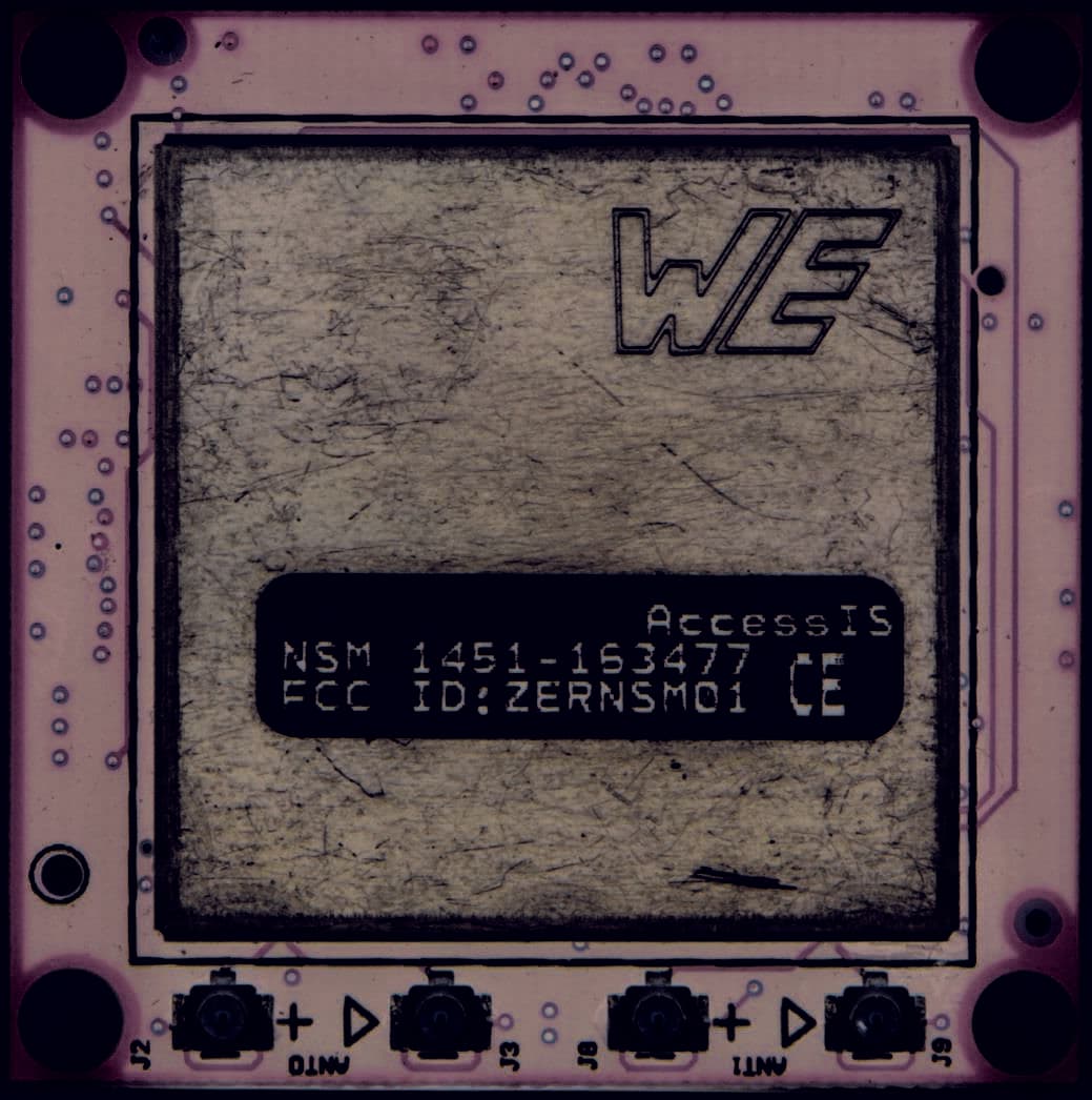
Click to zoom
Application Details
- Equipment Class
- DXX - Part 15 Low Power Communication Device Transmitter
- Date of Grant
- May 12, 2015
- Application Purpose
- Original Equipment
- Date of Application
- May 12, 2015
- Equipment Note
- NFC Smartcard Module (NSM01)
- Frequency Range
- 13.56000000 - 13.56000000
- Company
- Access Ltd
- Country
- United Kingdom
Documents & Files
Document Text
Text extracted from the exhibit documents filed with the FCC. Open a document above to read the original.
Users Manual
NFC Smartcard Module Hardware Installation Manual 1 CONFIDENTIAL DOCUMENT v0.2.3 NFC Smartcard Module Installation Manual NFC Smartcard Module Hardware Installation Manual 2 CONFIDENTIAL DOCUMENT v0.2.3 1. Introduction This document describes the hardware of the NFC smartcard module (NSM). The readers of this document would benefit if they have prior knowledge of the specifications mentioned in References section. 2. References The readers of this document shall have knowledge on the following specifications USB CCID rev1.1 : Specification for Integrated Circuit Cards Interface Devices ISO/IEC 14443-2 : Radio frequency power and signal interface ISO/IEC 14443-3 : Initialisation and anti-collision ISO/IEC 14443-4 : Transmission protocol Mifare contactless card (Classic 1K, Classic 4K and Ultralight) datasheets ISO/IEC 7816-3 : Electronic signals and transmission protocols ISO/IEC 7816-4 : Inter-Industry commands for interchange NSM USB/Serial software reference manual 3. FCC Statement This device complies with Part 15 of the FCC Rules. Operation is subject to the following two conditions: (1) this device may not cause harmful interference, and (2) this device must accept any interference received, including interference that may cause undesired operation. No changes shall be made to the equipment without the manufacturer’s permission as this may void the user’s authority to operate the equipment It is the responsibility of the product manufacturer to ensure compliance with FCC Part 15B with the NFC Smart Module integrated into their product. The host product using NSM module shall have the following text on a permanent label. Contains FCC ID : ZERNSM01 The label should be on a visible location outside the enclosure of the product. NFC Smartcard Module Hardware Installation Manual 3 CONFIDENTIAL DOCUMENT v0.2.3 4. Product pictures 4.1. Contactless NSM board – Top view HOST connector Smartcard Add-on Connector NOTE: The host connector connects to a 30 way FFC cable from the host system. This connector has the USB D+/- signals, Serial interface TX/RX signals and the Power and Ground. For more information on this connector pinout see Host connector section. The user can configure which interface the NSM shall use to communicate with the host. For more information on host interface selection see Host Interface Selection section. NFC Smartcard Module Hardware Installation Manual 4 CONFIDENTIAL DOCUMENT v0.2.3 4.2. Contactless NSM board Antenna connectors NFC Smartcard Module Hardware Installation Manual 5 CONFIDENTIAL DOCUMENT v0.2.3 4.3. Typical Hardware Setup The following diagram and pictures shows a typical setup for NSM module. NSM module Antenna #0Antenna #1 USB or Serial Host NFC Smartcard Module Hardware Installation Manual 6 CONFIDENTIAL DOCUMENT v0.2.3 The following pictures show a typical setup. Note that the antenna and the Serial/USB host shown in the pictures are for illustration only. The actual size and shape of the user’s antenna and host system may vary. Serial/ USB Host NSM Module Antenna #0 Antenna #1 NFC Smartcard Module Hardware Installation Manual 7 CONFIDENTIAL DOCUMENT v0.2.3 5. Installation 5.1. Hardware Prerequisites The following section shows the hardware required for the installation. Serial or USB host system where the NSM module will connect to. NFC module and 30 way host FFC cable Antenna and two U.FL coax cables – If two antennas are used then there will be two set of antenna boards and four coax cables NOTE: The Antenna and the U.FL coax cables can be supplied by Access IS or the user can design the antenna using the support provided by Access IS. U.FL cables are widely available from electronics stores like RS/Farnell. NFC Smartcard Module Hardware Installation Manual 8 CONFIDENTIAL DOCUMENT v0.2.3 5.2. Hardware Installation Steps The following details the installation steps with diagrams. 1, Turn OFF power for the host system before starting the installation 2, Connect the host system to the NFC module using the 30 way FCC cable as shown below. Please refer to Host connector section for the connector location and its pinouts. NFC module Host system NFC Smartcard Module Hardware Installation Manual 9 CONFIDENTIAL DOCUMENT v0.2.3 3, Connect the antenna to the NFC module using the coax cables. Antenna #0 Antenna #1 NSM Module 4, After the connections are done, select/verify the correct host interface selection on HOST_IFSEL_IO pins. Please refer to Host Interface Selection for HOST_IFSEL_IO pin settings. 5, If the product using the NSM module has a host cable, then a ferrite is required to be attached to the host cable. Please refer Cable Ferrite Specification for the characteristics of the required ferrite and the location of the ferrite on the host cable. NOTE : If single antenna operation is enabled, then firmware uses only Ant #1 – Port J8 and J9. Ant #0, port J2 and J3 are disabled. NOTE : Antenna coax cables are polarised. Connect the corresponding connectors with +ve markings and ground (triangle) markings on the antenna and NSM module NOTE : The cable ferrite is required to meet the FCC emissions requirement. The user should ensure that the cable ferrite is fitted in accordance to the specifications outlined in this manual. Failure to do so might void the FCC certification. NFC Smartcard Module Hardware Installation Manual 10 CONFIDENTIAL DOCUMENT v0.2.3 6, Power up the host system or connect the host adapter to the USB/Serial port. Now, the NFC module and the smart card module should start working. If the host interface is USB, then NSM module shall start enumerating as a HID device and a smartcard reader as shown below. 7, Application software can now communicate to NSM module through USB interface or through serial communication (See Serial Communication Settings). 5.3. Software Setup Depending on the host interface selected, please refer USB or Serial software reference manual. NFC Smartcard Module Hardware Installation Manual 11 CONFIDENTIAL …
Text truncated - open the document above for the full version.
External Photos
NFC Smartcard Module (NSM) RF shielding 1 CONFIDENTIAL DOCUMENT v0.0.0 Top View NFC Smartcard Module (NSM) RF shielding 2 CONFIDENTIAL DOCUMENT v0.0.0 Bottom View with Shield RF components shielded by metal shield above
ID Label/Location Info
NFC Smartcard Module (NSM) FCC Label Information 1 CONFIDENTIAL DOCUMENT v0.0 The following diagram shows the FCC label information. The labels shall be present on the metal shield of every NSM module. Access IS NSM XXX-YYYYYY FCC ID : ZERNSM01 The following picture shows a typical installation of the label.
Internal Photos
NFC Smartcard Module (NSM) Product Pictures 1 CONFIDENTIAL DOCUMENT v0.0.0 Top View NFC Smartcard Module (NSM) Product Pictures 2 CONFIDENTIAL DOCUMENT v0.0.0 Bottom View NFC Smartcard Module (NSM) Product Pictures 3 CONFIDENTIAL DOCUMENT v0.0.0 Bottom View without Shield
Test Report
UL VS LTD Pavilion A, Ashwood Park, Ashwood Way, Basingstoke, Hampshire, RG23 8BG, UK Telephone: +44 (0)1256 312000 Facsimile: +44 (0)1256 312001 TEST REPORT Test Report No. : UL-RPT-RP10615802JD02A V2.0 Manufacturer : Access-IS Model No. : NSM01 FCC ID : ZERNSM01 Technology : RFID – 13.56 MHz Test Standard(s) : FCC Parts 15.207, 15.209(a) & 15.225(d)(e) 1. This test report shall not be reproduced in full or partial, without the written approval of UL VS LTD. 2. The results in this report apply only to the sample(s) tested. 3. The sample tested is in compliance with the above standard(s). 4. The test results in this report are traceable to the national or international standards. 5. Version 2.0 supersedes all previous versions. Date of Issue: 20 April 2015 Checked by: Sarah Williams Engineer, Radio Laboratory Issued by : pp John Newell Quality Manager, UL VS LTD This laboratory is accredited by UKAS. The tests reported herein have been performed in accordance with its’ terms of accreditation. TEST REPORT SERIAL NO: UL-RPT-RP10615802JD02A VERSION 2.0 ISSUE DATE: 20 APRIL 2015 Page 2 of 19 UL VS LTD This page has been left intentionally blank. TEST REPORT SERIAL NO: UL-RPT-RP10615802JD02A VERSION 2.0 ISSUE DATE: 20 APRIL 2015 UL VS LTD Page 3 of 19 Table of Contents 1. Customer Information ................................................................................................................ 4 2. Summary of Testing ................................................................................................................... 5 2.1. General Information 5 2.2. Summary of Test Results 5 2.3. Methods and Procedures 5 2.4. Deviations from the Test Specification 5 3. Equipment Under Test (EUT) .................................................................................................... 6 3.1. Identification of Equipment Under Test (EUT) 6 3.2. Description of EUT 6 3.3. Modifications Incorporated in the EUT 6 3.4. Additional Information Related to Testing 6 3.5. Support Equipment 7 4. Operation and Monitoring of the EUT during Testing ............................................................. 8 4.1. Operating Modes 8 4.2. Configuration and Peripherals 8 5. Measurements, Examinations and Derived Results ................................................................ 9 5.1. General Comments 9 5.2. Test Results 10 5.2.1. Transmitter AC Conducted Spurious Emissions 10 5.2.2. Transmitter Radiated Spurious Emissions ≥ 30 MHz 13 5.2.3. Transmitter 20 dB Bandwidth 15 5.2.4. Transmitter Frequency Stability (Temperature & Voltage Variation) 16 6. Measurement Uncertainty ........................................................................................................18 7. Report Revision History ...........................................................................................................19 TEST REPORT SERIAL NO: UL-RPT-RP10615802JD02A VERSION 2.0 ISSUE DATE: 20 APRIL 2015 Page 4 of 19 UL VS LTD 1. Customer Information Company Name: Access-IS Address: 18 Suttons Business Park Reading Berkshire RG6 1AZ United Kingdom TEST REPORT SERIAL NO: UL-RPT-RP10615802JD02A VERSION 2.0 ISSUE DATE: 20 APRIL 2015 UL VS LTD Page 5 of 19 2. Summary of Testing 2.1. General Information Specification Reference: 47CFR15.225 Specification Title: Code of Federal Regulations Volume 47 (Telecommunications): Part 15 Subpart C (Radio Frequency Devices) - Section 15.225 Specification Reference: 47CFR15.207 and 47CFR15.209 Specification Title: Code of Federal Regulations Volume 47 (Telecommunications): Part 15 Subpart C (Intentional Radiators) - Sections 15.207 and 15.209 Site Registration: 209735 Location of Testing: UL VS LTD, Unit 3 Horizon, Wade Road, Kingsland Business Park, Basingstoke, Hampshire, RG24 8AH, United Kingdom Test Dates: 14 January 2015 to 15 April 2015 2.2. Summary of Test Results FCC Reference (47CFR) Measurement Result Part 15.207 Transmitter AC Conducted Spurious Emissions Part 15.209(a)/15.225(d) Transmitter Radiated Emissions ≥ 30 MHz Part 2.1049 Transmitter 20 dB Bandwidth Part 15.225(e) Transmitter Frequency Stability (Temperature & Voltage Variation) Key to Results = Complied = Did not comply 2.3. Methods and Procedures Reference: ANSI C63.4 (2009) Title: American National Standard for Methods of Measurement of Radio-Noise Emissions from Low-Voltage Electrical and Electronic Equipment in the Range of 9 kHz to 40 GHz Reference: ANSI C63.10 (2009) Title: American National Standard for Testing Unlicensed Wireless Devices 2.4. Deviations from the Test Specification For the measurements contained within this test report, there were no deviations from, additions to, or exclusions from the test specification identified above. TEST REPORT SERIAL NO: UL-RPT-RP10615802JD02A VERSION 2.0 ISSUE DATE: 20 APRIL 2015 Page 6 of 19 UL VS LTD 3. Equipment Under Test (EUT) 3.1. Identification of Equipment Under Test (EUT) Brand Name: Access-IS Model Name or Number: NSM01 Test Sample Serial Number: 1 Hardware Version Number: PCBM376901 Software Version Number: 1.01 FCC ID: ZERNSM01 3.2. Description of EUT The equipment under test was an RFID NSM module operating at 13.56 MHz. It is powered from a 5.0 VDC serial to USB port. 3.3. Modifications Incorporated in the EUT No modifications were applied to the EUT during testing. However, the following modification was made to one of the support equipment used in order to achieve compliance with radiated emissions testing: Addition of a ferrite clip (Wurth Elektronik Part No: 74271111) on to the USB cable. 3.4. Additional Information Related to Testing Tested Technology: RFID Category of Equipment: Transceiver Channel Spacing: Single channel device Operating Frequency: 13.56 MHz Power Supply Requirement: Nominal 5.0 V Minimum 4.25 V Maximum 5.75 V Tested Temperature Range: Minimum -20°C Maximum 50°C TEST REPORT SERIAL NO: UL-RPT-RP10615802JD02A VERSION 2.0 ISSUE DATE: 20 APRIL 2015 UL VS LTD Page 7 of 19 3.5. Support Equipment The following su…
Text truncated - open the document above for the full version.
Test Setup Photos
Access-IS FCC ID: ZERNSM01 UL-RPT-RP10615802JD02 IC: 9653A-NSM01 UL VS LTD 1 Test Setup Photographs for the NSM01 1. Radiated Emissions 1.1. Configuration 1 Photo 1 Photo 2 Access-IS FCC ID: ZERNSM01 UL-RPT-RP10615802JD02 IC: 9653A-NSM01 Radiated Emissions (continued) Photo 3 Note: The above photo shows the module housed in the test board. Access-IS FCC ID: ZERNSM01 UL-RPT-RP10615802JD02 IC: 9653A-NSM01 UL VS LTD 3 AC Conducted Emissions 1.2. Configuration 1 Photo 1 Access-IS FCC ID: ZERNSM01 UL-RPT-RP10615802JD02 IC: 9653A-NSM01 AC Conducted Emissions (continued) Photo 2 Photo 3
Contact Information
Applicant
Tanya Newell(Senior Design Engineer)
Technical Contact
Access LtdTanya Newell
[email protected]00441189663333
18 Suttons Business Park · Reading · United Kingdom
Non-Technical Contact
Access LtdLorraine Hall
[email protected]00441189663333
Test Firm
UL VS LtdDarren Rust
Technical Specifications
| # | Rule Parts | Frequency Range | Power Output |
|---|---|---|---|
| 1 | 15C | 13.56 MHz - 13.56 MHz | - |
Other Applications from Access Ltd
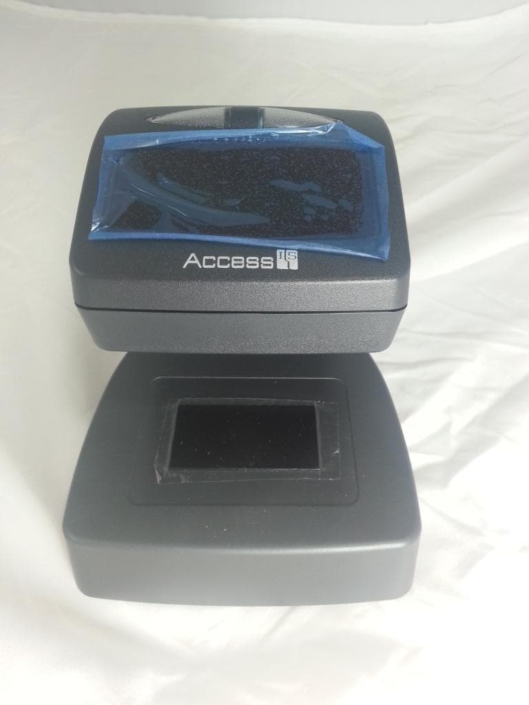
ZERBGR135
Sep 01, 2014Boarding Gate Reader
Equipment Class
DXX - Part 15 Low Power Communication Device Transmitter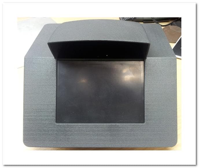
ZEROCR640
Aug 12, 2012Optical Document Reader with eMRTD
Equipment Class
DXX - Part 15 Low Power Communication Device Transmitter
ZEROCR601
May 08, 2011Optical MRZ Identity Checker with eMRTD
Equipment Class
DXX - Part 15 Low Power Communication Device Transmitter