ZEROCR640Optical Document Reader with eMRTD
Access Ltd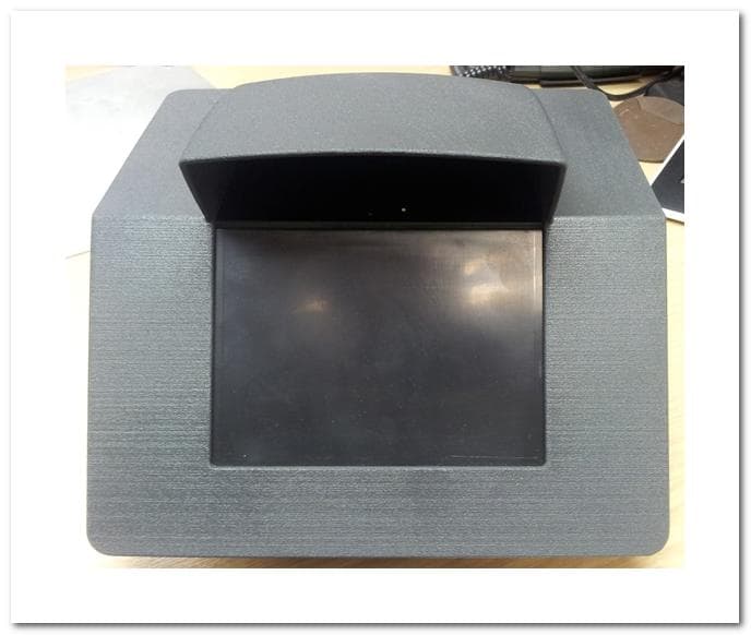
Click to zoom
Application Details
- Equipment Class
- DXX - Part 15 Low Power Communication Device Transmitter
- Date of Grant
- Aug 12, 2012
- Application Purpose
- Original Equipment
- Date of Application
- Aug 12, 2012
- Equipment Note
- Optical Document Reader with eMRTD
- Frequency Range
- 13.56000000 - 13.56000000
- Company
- Access Ltd
- Country
- United Kingdom
Documents & Files
Document Text
Text extracted from the exhibit documents filed with the FCC. Open a document above to read the original.
Users Manual
OCR640 Series Optical MRZ Identity Checker with eMRTD User Guide Model outline The OCR640 captures the full page image and decode the machine readable zone (MRZ) from documents complying to ICAO9303. The OCR640 has an integrated RFID reader enables the device to simultaneously decode the contents of an e-passport or contactless smart card. Main features Fixed cover 1. OCR reading window2. Power and read indicators 3. Document guide4. RJ50 connector5. 1 2 4 3 How to read a document with OCR data Orient the document correctly with the MRZ text down under the lid. Follow the instructions provided by the host application. If a read is unsuccessful then re-present the document; for persistent errors refer to the Troubleshooting section. How to read a document with data stored on the chip Orient the document correctly with the MRZ text down under the lid. Follow the instructions provided by the host application. If a read is unsuccessful then re-present the document; for persistent errors refer to the Troubleshooting section. Document orientation The document should be placed with the Machine Readable Zone (MRZ) facing downwards on the document guide. Slide the document under the cover until fully inserted. Connection Plug in the USB connection to the host device and connect the DC power connector to the power supply. The power indicator will illuminate green. The OCR640 requires an application programme to be running on the host computer: please refer to your system administrator. 5 Regulatory compliance FCC compliance and Industry Canada compliance This device complies with Part 15 of the FCC rules and with RSS-210 Issue 8. Operation is subject to the following two conditions: • This device may not cause harmful interference; • This device must accept any interference received including interference that may cause undesired operation. WARNING! Changes or modifications made to the system that are not approved by the party responsible for compliance could void the user’s authority to operate the equipment. Note: This equipment has been tested and found to comply with the limits for a Class A digital device, pursuant to part 15 of the FCC Rules. These limits are designed to provide reasonable protection against harmful interference when the equipment is operated in a commercial environment. This equipment generates, uses, and can radiate radio frequency energy and, if not installed and used in accordance with the instruction manual, may cause harmful interference to radio communications. Operation of this equipment in a residential area is likely to cause harmful interference in which case the user will be required to correct the interference at his own expense. This device complies with Industry Canada licence-exempt RSS standard(s). Operation is subject to the following two conditions: (1) This device may not cause harmful interference, and (2) This device must accept any interference received, including interference that may cause undesired operation. •Le présent appareil est conforme aux CNR d’Industrie Canada applicables aux appareils radio exempts de licence. L’exploitation est autorisée aux deux conditions suivantes : (1) l’appareil ne doit pas produire de brouillage, et (2) l’utilisateur de l’appareil doit accepter tout brouillage radioélectrique subi, même si le brouillage est susceptible d’en compromettre le fonctionnement. This class A digital apparatus complies with Canadian ICES-003. Cet appareil numérique de la classe A est conforme à la norme NMB-003 du Canada. CE Marking by the CE symbol indicates compliance of this system to the applicable Council Directives of the European Union, including the EMC Directive (2004/108/EC) and the Low Voltage Directive (2006/95/EC). A “Declaration of Conformity” in accordance with the applicable directives has been made and is on file at Access Ltd. WEEE (EC Directive Waste Electrical & Electronic Equipment) This product should not be disposed with other commercial or household wastes at the end of its working life. Go to www.access-is.com/weee for more information. © 2010 by Access Limited; Access IS is the trading name of Access Limited Version 1.0 29th March 2011 Troubleshooting ProblemPossible CauseSolution Persistent bad readsThe document is oriented incorrectly in the document guide Refer to document orientation section Poor reading techniqueRefer to authorised trainer to check technique Dirty windowRefer to Service & cleaning section Persistently not reading Bad connection between host and OCR640 Check all connectoions Application not running on host or OCR640 not working properly Consult with technical staff MRZ reading but RFID failing RFID antenna not installedEnsure the the smartcard RFID is installed properly and is not conflicting Document being removed prior to RFID read completion Refer to authorised trainer to check technique Techniques for reading reliably Do Hold document still during read process1. Ensure document is fully inserted under hinged cover2. Don’t Remove document until host application instructs you to do so1. Insert damaged or defaced documents on the reader2. Service and cleaning The module has no serviceable parts and must not be opened. The reading window can be cleaned by sliding a soft clean lint-free cloth under the lid and cleaning the glass window. Warranty statement (a) Access Limited (ACCESS) hardware Products are warranted against defects in workmanship and materials for a period of twelve (12) months from the date of shipment by ACCESS or an authorised reseller to its customer, but in no event more than fifteen (15) months from shipment of the Products by ACCESS, unless otherwise provided by ACCESS in writing, provided the Product remains unmodified and is operated under normal and proper conditions. (b) Spare parts (i.e. Parts, components, or subassemblies sold by ACCESS for use in the service and maintenance of Products) are warranted against defects in workmanship and materials for a period of thirty…
Text truncated - open the document above for the full version.
Block Diagram
OCR640 – Signal Paths & Operating Frequencies
External Photos
FRONT VIEW – WITH EXAMPLE FASCIA SIDE VIEW – MOUNTED IN TEST FRAME REAR VIEW – MOUNTED IN TEST FRAME
ID Label/Location Info
TK SEE NOTES OCR640 OEM LABEL PLACEMENT LOCATION AC3211 DRAWING NO. DRAWN BY ISSUE ENG INIT. DATE 21/04/2012 FURNISHED IN CONFIDENCE BY ACCESS LTD.THE COPYRIGHT OF THIS DRAWING IS THE PROPERTY OFACCESS LTD. THE DRAWING IS SUPPLIED IN CONFIDENCE A ND MUST NOT BE USED FOR ANY PURPOSE OTHER THAN THAT FO R WHICH IT IS SUPPLIED. IT MUST NOT BE REPRODUCED WIT HOUT THE EXPRESS WRITTEN PERMISSION OF ACCESS LTD. TOLERANCESX = +/- 0.5X.0 = +/- 0.2X.00 = +/- 0.1ANG = +/- 0.5UNLESS OTHERWISE STATED DIMENSIONS IN MM SCALE 1:1 MATERIALFINISH ACCESS LTD. READING, BERKSHIRE. TITLE DRAWING NO. AC3211 SEE NOTES 02 CHECKED A2 SCALE: 2:1 51 76 5 5 29,8 24,7 - USE ONLY APPROVED ACCESS LTD CABLE.- ACCESS LTD PART NUMBER: 5KBD2395- DEVICE IS USB DATA/ 5V LOW POWER TYPE. ! CAUTION ! 51 2 6
Internal Photos
LEFT SIDE VIEW RIGHTSIDE VIEW GENERAL INNER VIEW INNER VIEW REAR CAMERA BOARD RFID CONTROLLER INTELLIGENT ILLUMINATION CONTROLLER MAIN INTERFACE CAMERA CONTROLLER TRI COLOUR LED BOARD UV LED BOARD TOP ANTENNA ( UNDER GLASS ) FRONT ANTENNA
Operational Description
OCR640 – Operational Description OCR640 is an USB connected passport reader which has a Camera Imager and a RFID contactless reader. The camera is used to capture images by the host application, which then decodes the passport MRZ data. The MRZ data is then sent to the RFID reader to authenticate with the RFID chip in the passport to read the data. The following figure shows the hardware architecture of OCR640. Fig 1: OCR640 Hardware Architecture The USB Hub #1 is mainly used as a placeholder for future expansions. The USB hub #2 is used to connect the camera and the RFID to the USB upstream bus. The USB camera imager controls both the sounder and the lighting board through SPI and I2C respectively. The Lighting board is quite flexible to provide UV or IR or white illumination as requested by the imager. The RFID contactless reader drives two independent antennas. There is one antenna around the glass window. This antenna will be referred as antenna #1 in this document. The other antenna is behind the front face of the product. This antenna will be referred as antenna #2 in this document. Typically, both these antennas will be scanning for RFID passports – one at a time. High Speed USB Hub (#1 & #2): Device classification 2 port USB High speed hub Operating Voltage / Current 3.3V / 150mA Digital/Analog Digital circuitry Crystal Frequency 24 MHz PLL Multiplier x20 (480 MHz internal frequency) Data transfer rate 480Mbps Intentional Radiation No Software requirements USB host should have generic USB hub driver. All windows machine supports this USB hub class and it should start up right away. There are not application software requirements. Operational Description: High speed USB hub #1: This high speed USB hub is used for future extension of the product. High speed USB hub #2: This High speed USB hub provides USB connectivity to the RFID and the camera. It provides two USB downstream ports. One of the downstream ports is connected to a RFID full speed device and the other is connected to a 1.3 Mega pixel imager. Camera Imager: Device classification USB 2.0 High speed camera Operating Voltage / Current 5V / 150mA Digital/Analog Digital circuitry Crystal Frequency 24 MHz PLL Multiplier x20 (480 MHz internal frequency) Data transfer rate 480Mbps Intentional Radiation No Image resolution 2048 x 1536 (3.1 Mega pixel) Software requirements USB host should have Access IS camera drivers installed. The camera starts-up only if camera application software (like Amcap or IScap) is running. The camera shuts down when then application software is closed. Operational Description: The camera imager is a USB 2.0 high speed camera capable of streaming images at 3.1 Mega pixel resolutions. The data from the camera reaches the USB host through the USB high speed hub. It should be noted that the camera is in shutdown state when there is no application software running. For normal operation camera application software like Amcap or IScap should be running. It should be noted that the lighting circuit is controlled by the imager. The right illumination could be selected appropriately by the imager circuit and this kind of arrangement helps the USB host software to control the illumination. The following diagram shows the internal blocks of the camera imager along with the lighting circuit. Fig 2: Camera imager internal block diagram Lighting board: Device classification Boost regulator for lighting application Operating Voltage / Current 5V / 250mA Digital/Analog Analog circuitry Switching Frequency ~500KHz LED drive Voltage / Current ~25V / 20mA (Drives a string of IR, UV, White LEDs) Intentional Radiation No Software requirements None. Starts up as soon as power is applied Operational Description: The lighting board drives a set of IR, UV and white LEDs. The circuit is controlled by the imager circuit through I2C interface. The choice of IR/UV/White illumination is done by the host application and is handed down to the lighting board through the I2C interface. The lighting board has a step up DC-DC converter and current controlled LED drivers to accomplish the intended purpose. Sounder: Device classification Audible tone generator Operating Voltage / Current 3.3V / 20mA Digital/Analog Digital circuitry Operating Frequency 8 MHz Intentional Radiation No Software requirements None. Camera imager digital circuit controls the tone generator. The communication is through SPI interface operating at 100KHz. Operational Description: Sounder block is basically a small microcontroller that generates tones. The sounder controller receives commands from the camera digital circuit on which tone it has to play. With this kind of arrangement, the USB host software can access the sounder through the camera digital circuit. RFID Contactless Reader RFID contactless reader contains both digital and analog section. Information on these two sections are provided below. RFID Contactless Reader – Digital Section Device classification USB full speed device Operating Voltage / Current 5V / 50mA Digital/Analog Digital circuitry Crystal Frequency 8 MHz PLL Multiplier x6 (48 Mhz internal frequency) Data transfer rate 12Mbps Intentional Radiation No Software requirements Microsoft CCID smartcard driver is required. Only if the driver is loaded in the host machine the digital section will enable the RFID analog section. There are no application software requirements to get the RFID active. However, to reader RFID passport application software (like Golden reader tool) is required. RFID Contactless Reader – Analog Section Device classification RFID transceiver Operating Voltage / Current 5V / 150mA RFID protocol ISO14443 Type A and Type B Digital/Analog Analog circuitry Crystal Frequency 13.56 MHz PLL Multiplier None RF Data transfer rate 424 Kbps Intentional Radiation Yes Carrier frequency 13.56 Mhz +/- 7 KHz Sub Carrier frequency 847 KHz (max) Number of Antenna 2 Output power < 250 mW RF field strength 6 A/m (RMS) Software requirements R…
Text truncated - open the document above for the full version.
Test Report
TEST REPORT FROM RFI GLOBAL SERVICES LTD Test of: OCR640 FCC ID: ZEROCR640 IC Certification Number: 9653A-OCR640 To: FCC Part 15.225: 2011 Subpart C, RSS-210 Issue 8 December 2010 & RSS-Gen Issue 3 December 2010 Test Report Serial No.: RFI-RPT-RP82375JD01A V4.0 Version 4.0 Supersedes All Previous Versions This Test Report Is Issued Under The Authority Of John Newell, Group Quality Manager: Checked By: Ian Watch Signature: Date of Issue: 13 August 2012 This report is issued in Adobe Acrobat portable document format (PDF). It is only a valid copy of the report if it is being viewed in PDF format with the following security options not allowed: Changing the document, Selecting text and graphics, Adding or changing notes and form fields. This report may not be reproduced other than in full, except with the prior written approval of RFI Global Services Ltd. The results in this report apply only to the sample(s) tested. TEST REPORT SERIAL NO: RFI-RPT-RP82375JD01A V4.0 VERSION 4.0 ISSUE DATE: 13 AUGUST 2012 Page 2 of 23 RFI Global Services Ltd This page has been left intentionally blank. TEST REPORT SERIAL NO: RFI-RPT-RP82375JD01A V4.0 VERSION 4.0 ISSUE DATE: 13 AUGUST 2012 RFI Global Services Ltd Page 3 of 23 Table of Contents 1. Customer Information .................................................................................................................. 4 2. Summary of Testing ..................................................................................................................... 5 2.1. General Information 5 2.2. Summary of Test Results 5 2.3. Methods and Procedures 6 2.4. Deviations from the Test Specification 6 3. Equipment Under Test (EUT) ....................................................................................................... 7 3.1. Identification of Equipment Under Test (EUT) 7 3.2. Description of EUT 7 3.3. Modifications Incorporated in the EUT 7 3.4. Additional Information Related to Testing 8 3.5. Support Equipment 8 4. Operation and Monitoring of the EUT during Testing ............................................................... 9 4.1. Operating Modes 9 4.2. Configuration and Peripherals 9 5. Measurements, Examinations and Derived Results ................................................................ 10 5.1. General Comments 10 5.2. Test Results 11 5.2.1. Transmitter AC Conducted Spurious Emissions 11 5.2.2. Transmitter Fundamental Field Strength 14 5.2.3. Transmitter Radiated Spurious Emissions 16 5.2.4. Transmitter Band Edge Radiated Emissions 19 5.2.5. Transmitter 20 dB Bandwidth 20 5.2.6. Transmitter Frequency Stability (Temperature & Voltage Variation) 21 6. Measurement Uncertainty .......................................................................................................... 22 Appendix 1. Test Equipment Used ................................................................................................ 23 TEST REPORT SERIAL NO: RFI-RPT-RP82375JD01A V4.0 VERSION 4.0 ISSUE DATE: 13 AUGUST 2012 Page 4 of 23 RFI Global Services Ltd 1. Customer Information Company Name: Access-IS Address: 18 Suttons Business Park Reading Berkshire RG6 1AZ United Kingdom TEST REPORT SERIAL NO: RFI-RPT-RP82375JD01A V4.0 VERSION 4.0 ISSUE DATE: 13 AUGUST 2012 RFI Global Services Ltd Page 5 of 23 2. Summary of Testing 2.1. General Information Specification Reference: 47CFR15.225 Specification Title: Code of Federal Regulations Volume 47 (Telecommunications) 2011: Part 15 Subpart C (Radio Frequency Devices) - Section 15.225 Specification Reference: 47CFR15.107 and 47CFR15.109 Specification Title: Code of Federal Regulations Volume 47 (Telecommunications) 2011: Part 15 Subpart B (Radio Frequency Devices) - Sections 15.107 and 15.109 Specification Reference: 47CFR15.209 Specification Title: Code of Federal Regulations Volume 47 (Telecommunications) 2011: Part 15 Subpart C (Intentional Radiators) - Section 15.209 Specification Reference: RSS-Gen Issue 3 December 2010 Specification Title: General Requirements and Information for the Certification of Radio Apparatus Specification Reference: RSS-210 Issue 8 December 2010 Specification Title: Licence-exempt Radio Apparatus (All Frequency Bands): Category I Equipment. Site Registration: FCC: 209735; Industry Canada: 3245B-2 Location of Testing: RFI Global Services Ltd, Wade Road, Basingstoke, Hampshire, RG24 8AH. Test Dates: 07 July 2011 to 16 July 2012 2.2. Summary of Test Results FCC Reference (47CFR) IC Reference Measurement Result Part 15.207 RSS-Gen 7.2.4 Transmitter AC Conducted Emissions Part 15.225(a)(b)(c)(d) RSS-Gen 4.8 RSS-210 A2.6 Transmitter Fundamental Field Strength Part 15.209(a)/ 15.225(d) RSS-Gen 4.9 RSS-210 A2.6 Transmitter Radiated Emissions Part 15.209(a)/ 15.225(c)(d) RSS-Gen 4.9 RSS-210 A2.6 Transmitter Band Edge Radiated Emissions Part 2.1049 RSS-Gen 4.6.1/4.6.3 Transmitter 20 dB Bandwidth Part 15.225(e) RSS-Gen 4.7 RSS-210 A2.6 Transmitter Frequency Stability (Temperature & Voltage Variation) Key to Results = Complied = Did not comply TEST REPORT SERIAL NO: RFI-RPT-RP82375JD01A V4.0 VERSION 4.0 ISSUE DATE: 13 AUGUST 2012 Page 6 of 23 RFI Global Services Ltd 2.3. Methods and Procedures Reference: ANSI C63.4 (2009) Title: American National Standard for Methods of Measurement of Radio-Noise Emissions from Low-Voltage Electrical and Electronic Equipment in the Range of 9 kHz to 40 GHz Reference: ANSI C63.10 (2009) Title: American National Standard for Testing Unlicensed Wireless Devices 2.4. Deviations from the Test Specification For the measurements contained within this test report, there were no deviations from, additions to, or exclusions from the test specification identified above. TEST REPORT SERIAL NO: RFI-RPT-RP82375JD01A V4.0 VERSION 4.0 ISSUE DATE: 13 AUGUST 2012 RFI Global Services Ltd Page 7 of 23 3. Equipment Under Test (EUT) 3.1. Identification of Equipment Under Test (EUT) Brand Name: Access-IS Model Name or Number: OCR640 Serial Number: ENG001 Hardware Version Number: EN…
Text truncated - open the document above for the full version.
Contact Information
Applicant
Tanya Newell(Senior Design Engineer)
Non-Technical Contact
Access LtdLorraine Hall
[email protected]+441189663333
Test Firm
UL VS LtdDarren Rust
Technical Specifications
| # | Rule Parts | Frequency Range | Power Output |
|---|---|---|---|
| 1 | 15C | 13.56 MHz - 13.56 MHz | - |
Other Applications from Access Ltd
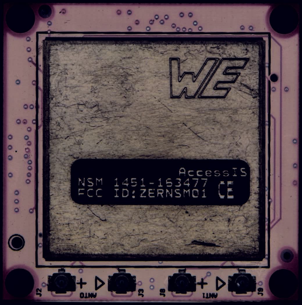
ZERNSM01
May 12, 2015NFC Smartcard Module (NSM01)
Equipment Class
DXX - Part 15 Low Power Communication Device Transmitter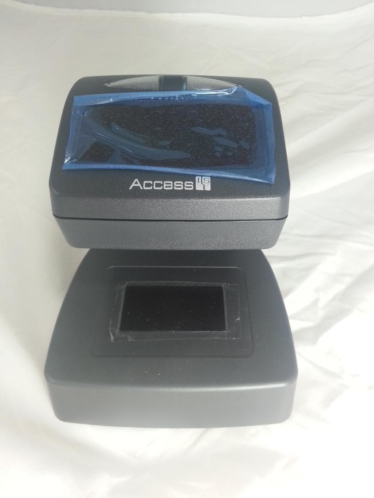
ZERBGR135
Sep 01, 2014Boarding Gate Reader
Equipment Class
DXX - Part 15 Low Power Communication Device Transmitter
ZEROCR601
May 08, 2011Optical MRZ Identity Checker with eMRTD
Equipment Class
DXX - Part 15 Low Power Communication Device Transmitter