ZHXMPT2500Wireless Camera
MicroPower Technologies, Inc.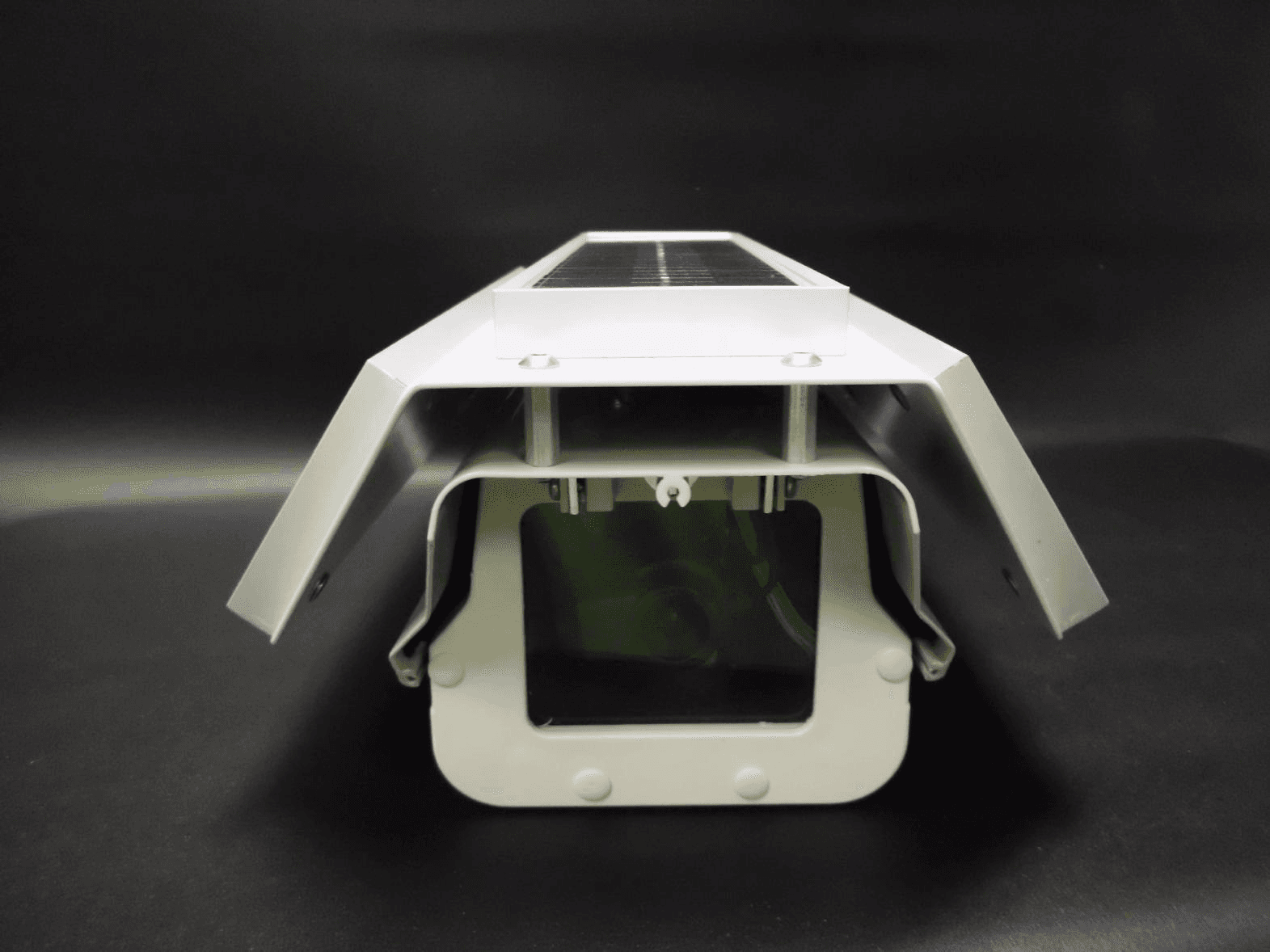
Click to zoom
Application Details
- Equipment Class
- DTS - Digital Transmission System
- Date of Grant
- Jul 26, 2011
- Application Purpose
- Original Equipment
- Date of Application
- Jul 25, 2011
- Equipment Note
- Wireless Camera
- Frequency Range
- 2412.00000000 - 2462.00000000
- Country
- United States
Documents & Files
Document Text
Text extracted from the exhibit documents filed with the FCC. Open a document above to read the original.
Users Manual
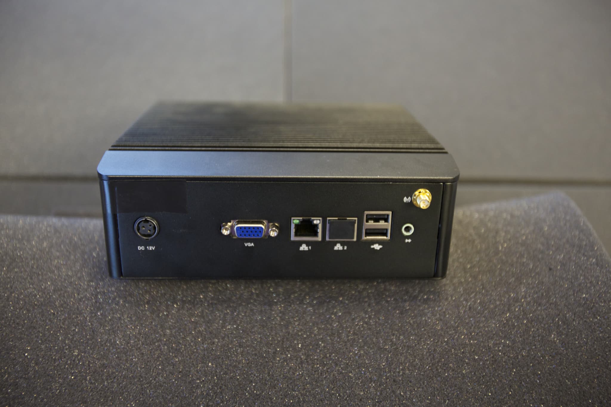
MPT 2500 Rugged-i™ Solar Wireless Video Camera & MPT2700 MiniHub™ Wireless Video Hub Quick Start Guide MicroPower Technologies, Inc. 4225 Executive Square, Suite 430 La Jolla, CA 92037 858-768-5780 www.micropowerapp.com Installation Guide v1.1©2011 MicroPower Technologies, Inc.1 Before installation, please refer to the Read Me First documentation included with this product for installation safety information. Step 1: Setting up the MiniHub Wireless Video Hub MiniHub Rear View 1.1.Connect the two (2) 2.4 GHz purple antennas and the one (1) 900 MHz yellow antenna using the corresponding color-coded indicators above each antenna connector on the MiniHub. 1.2.Connect the AC power cable to the MiniHub and plug into a power source. 1.3.Connect your mouse and keyboard (not included) to the MiniHub using any of the USB connectors. 1.4.Connect your monitor (not included) to the rear of the MiniHub. 1.5.Power on the MiniHub using the toggle power button on the rear of the unit. 1.6.Proceed to Step 2: Setting up the Rugged-I Camera. Step 2: Setting up the Rugged-i Camera WARNING: Do not connect the camera batteries until AFTER the antennas have been connected. The Rugged-i camera ships with a fully charged battery pack. Rugged-i Side View Rugged-i Rear View 2.1.Connect the shorter 2.4 GHz antenna (purple) and the taller 900 MHz antenna (yellow) using the corresponding color-coded indicators next to each antenna connector on the top of the camera housing. 2.2.NOTE: The camera ships with a fully charged battery pack, but should the camera require charging, please follow this step. Open the camera housing using the safety latch at the rear of the unit. Attach the battery charger cord to the battery connector. Charge the battery until the charge completion light is illuminated. After charging, disconnect the battery charger cord and re-connect the battery connector. The LED indicator light should glow red when the battery is connected. Close the camera housing then lock the safety latch. 2.3.Attach the mounting arm to the bottom of the Rugged-i camera housing using the included hardware. Installation Guide v1.1©2011 MicroPower Technologies, Inc.2 2.4.Mount the camera in the desired surveillance location with the mounting arm, then point the camera to the desired surveillance position. The camera should be placed in an area which receives an adequate amount of direct sunlight throughout the day, however the solar panels do not require alignment with the sun. The locking mounting bracket will allow the camera to remain in this position after it is installed. Step 3: Configuring the MiniHub Wireless Video Hub to View Video 3.1.After the MiniHub is powered on and the Rugged-i camera(s) has been placed in its desired location, the MiniHub can be configured. 3.2.On the MiniHub computer desktop, launch the Demo icon located in the top left corner. MiniHub Computer Desktop 3.3.This will launch the camera association input window. At the “enter password” prompt, enter the password, demo. 3.4.At the “enter wifi channel” prompt, enter an available wireless channel. Camera Association Input Window 3.5.The hub will then begin the camera association process and the camera image will appear on the screen. Installation Guide v1.1©2011 MicroPower Technologies, Inc.3 Camera Image Window Step 4: Adjusting the Camera Image Camera Lens Close-up View 4.1While viewing the camera image in the MiniHub camera image window, adjustments can be made to the camera’s focal length, iris or focus. 4.2.Open the camera housing using the safety latch at the rear of the unit. The camera imager is located just behind the housing window. 4.2.1.To adjust focal length, turn the focal length locking knob counter-clockwise to unlock. Rotate the focal length adjustment ring at the rear of the lens to set. Turn the focal length locking knob clockwise to lock back into place. 4.2.2.To adjust iris, turn the iris locking knob counter-clockwise to unlock. Slide the iris locking knob to the right or left to set. Turn the iris locking knob clockwise to lock back into place. 4.2.3.To focus, turn the focus locking knob counter-clockwise to unlock. Rotate the focus adjustment ring at the front of the lens to set. Turn focus locking knob clockwise to lock in place. 4.3.After the imager adjustments have been completed, close the camera housing and lock the latch into place. 4.4.After this step, setup is complete and the Rugged-i camera is ready for use. Installation Guide v1.1©2011 MicroPower Technologies, Inc.4 INFORMATION TO USER This device complies with Part 15 of the FCC Rules. Operation is subject to the following two conditions: (1) This device may not cause harmful interference, and (2) This device must accept any interference received, including interference that may cause undesired operation. This equipment has been tested and found to comply with the limits for Class B Digital Device, pursuant to Part 15 of the FCC Rules. These limits are designed to provide reasonable protection against harmful interference in a residential installation. This equipment generates and can radiate radio frequency energy and, if not installed and used in accordance with the instructions, may cause harmful interference to radio communications. However, there is no guarantee that interference will not occur in a particular installation. If this equipment does cause harmful interference to radio or television reception, which can be determined by turning the equipment off and on, the user is encouraged to try to correct the interference by one or more of the following measures. • Reorient or relocate the receiving antenna • Increase the separation between the equipment and receiver • Connect the equipment into an outlet on a circuit different from that to which the receiver is connected • Consult the dealer or an experienced radio/TV technician for help Any changes or modifications not expressly approved by the party responsible for compliance could void the user’s aut…
Text truncated - open the document above for the full version.
Cover Letter(s)
Nemko Canada Inc 303 River Road Ottawa, Ontario, Canada K1V 1H2 Attn: Director of Certification FCC ID: ZHXMPT2500 Authority to Act as Agent On our behalf, I appoint Alan Laudani of Nemko USA Inc., 11696 Sorrento Valley Rd, San Diego, CA, USA to act as our agent in the preparation of this application for equipment certification. I certify that submitted documents properly describe the device or system for which equipment certification is sought. I also certify that each unit manufactured, imported or marketed, as defined in Federal Communication Commission’s regulations will have affixed to it a label identical to that submitted for approval with this application. For instances where our authorized agent signs the application for certification on our behalf, I acknowledge that all responsibility for complying with the terms and conditions for certification, as specified by Nemko Canada Inc, still resides with MicroPower Technologies, Inc. 4225 Executive Square, Suite 430, La Jolla, CA, 92037. Date of Expiration: 16 November, 2011 Dated this 16th of May, 2011 Sincerely, Mark Sapper Hardware Development Manager 4225 Executive Square, Suite 430 La Jolla, CA 92037 www.micropowerapp.com
Cover Letter(s)
4225 Executive Square, Suite 430 La Jolla, CA 92037 www.micropowerapp.com Nemko Canada Inc 303 River Road Ottawa, Ontario, Canada K1V 1H2 Attn: Director of Certification Re: Justification for Professional Installation for FCC ID#: ZHXMPT2500 The MicroPower MPT2500 Camera uses standard N style connectors on its antennas. These provide a rugged, weatherproof solution that ensures a quality long-term connection in outdoor environments. To protect against unauthorized antenna connections, the Cameras will always be installed by trained professionals. The target markets for the MPT2500 camera are commercial and industrial surveillance applications. These markets are serviced by systems integrators that provide installation and setup services to the end customers. The price point of the camera system is significantly greater than comparable consumer grade products, and therefore beyond the price range of a retail consumer. The MPT2500 is marketed exclusively to these systems integrators and distributors, and is not sold directly to end-user customers through retail outlets, or mail order. The systems integrators employ trained installation professionals. Only these trained installers are given access to test modes that report signal strength and error rate statistics. These statistics are used to select appropriate installation locations, as well as to properly align the antennas. Dated this 28th of June 2011 Sincerely, Mark Sapper Hardware Development Manager
Cover Letter(s)
4225 Executive Square, Suite 430 La Jolla, CA 92037 www.micropowerapp.com Nemko Canada Inc 303 River Road Ottawa, Ontario, Canada K1V 1H2 Attn: Director of Certification Re: Request of Permanent Confidentiality for FCC ID#: ZHXMPT2500 Pursuant to Sections 0.457(d)(I)(ii) and 0.459 of the Commission’s Rules, the Applicant hereby requests confidential treatment of accompanying information as outlined below: Schematics, Parts List (BOM), Operating Description, Block Diagrams. This request is made under the provisions of Section 0.457(d) of the FCC Rules and Section 552(b)(4) of the Freedom of Information Act. These sections authorize a withholding from public inspection, materials containing trade secrets and proprietary information not customarily released to the public. The public disclosure of these matters might be harmful to the Applicant and provide unjustified benefits to its competitors. Dated this 16th of May 2011 Sincerely, Mark Sapper Hardware Development Manager
Cover Letter(s)
4225 Executive Square, Suite 430 La Jolla, CA 92037 www.micropowerapp.com Nemko Canada Inc 303 River Road Ottawa, Ontario, Canada K1V 1H2 Attn: Director of Certification Re: Request of short term Confidentiality for FCC ID#: ZHXMPT2500 Pursuant to Sections 0.457(d)(I)(ii) and 0.459 of the Commission’s Rules, the Applicant hereby requests confidential treatment of accompanying information as outlined below: Circuit Board Photos The above materials contain trade secrets and proprietary information not customarily released to the public. The public disclosure of these matters might be harmful to the Applicant and provide unjustified benefits to its competitors. Pursuant to Rule 0.457(d)(I)(ii), the Applicant requests that public disclosure of the above referenced materials not be made until 45 days after the date of the Grant for this Application. Dated this 16th of May 2011 Sincerely, Mark Sapper Hardware Development Manager
External Photos
Camera exterior side view Camera exterior side view Camera exterior front view Camera exterior rear view Camera exterior top view Camera exterior bottom view Camera exterior with antennas Camera exterior RF connectors close up
ID Label/Location Info
Label location
Internal Photos
Camera interior base Camera interior lid Camera PCBPA PCBImager PCB Camera interior RF connector detail Camera circuit board top view Camera circuit board bottom view PA/Solar circuit board top view PA/Solar circuit board bottom view Imager circuit board top view Imager circuit board bottom view Imager Interface circuit board top view Imager Interface circuit board bottom view
RF Exposure Info
S = power density P = power input to the antenna G = power gain of the antenna in the direction of interest relative to isotropic R = distance to the center of radiation of the antenna output power 11.47 (dBm) 28.07 (dBm) output power 14 (mW) 641 (mW) antenna gain 5 (dBi) 7 (dBi) antenna gain 3.162 (numeric) 5.012 (numeric) distance 20 (cm) 20 (cm) duty cycle 100 (%) 100 (%) frequency 909.8 (MHz) 1900 (MHz) MPE limit 0.607 (mW/cm^2) 1.000 (mW/cm^2) power density 0.0088 (mW/cm^2) 0.6393 (mW/cm^2) margin 18.3712 (dB) 1.9427 (dB) 0.00883 + 0.639 0.648 <1
RF Exposure Info
L-COM, INC. 45 BEECHWOOD DRIVE NORTH ANDOVER, MA 01845 WWW.L-COM.COM E-MAIL: [email protected] PHONE: 1-800-343-1455 FAX: 1-978-689-9484 © L-com, Inc. All Rights Reserved. L-com Global Connectivity and the L-com logo are registered marks. HyperLink Wireless 900 MHz 5 dBi SMA Male High Performance "Rubber Duck" Wireless LAN Antenna Applications and Features Applications: y 900MHz ISM Band y Cellular Band Applications y 900MHz Digital Spread Spectrum Radios y 900MHz Telemetry Products y GSM y RFID y Wireless Video Transmitters and Receivers y Multipoint and Mobile Applications Features: y Better performance then most stock AP antennas y Flexible "Rubber Duck" antenna y Tilt and swivel design y SMA Male Connector y RoHS Compliant Model: HG905RD-SM Description This high performance 900MHz omnidirectional "rubber-duck" antenna provides broad coverage and 5 dBi gain. It is a coaxial sleeve design with an omni-directional pattern. It is ideally suited for 900MHz ISM band applications as well as cellular applications. Measuring 16.9" long, this flexible antenna features a tilt-and-swivel SMA Male connector, allowing them to be used vertically, at a right angle, or any angle in-between. It is suitable as a replacement RF antenna for 900MHz radios that are equipped with RP- SMA connectors such as wireless video transmitters and receivers, 900MHz digital spread spectrum radios and more. Specifications Electrical Specifications Frequency 900-930 MHz Gain 5 dBi Horizontal Beam Width 360° Impedance 50 Ohm Max. Power 50W VSWR ≤ 2.5 Lightning Protection DC Ground L-COM, INC. 45 BEECHWOOD DRIVE NORTH ANDOVER, MA 01845 WWW.L-COM.COM E-MAIL: [email protected] PHONE: 1-800-343-1455 FAX: 1-978-689-9484 © L-com, Inc. All Rights Reserved. L-com Global Connectivity and the L-com logo are registered marks. Mechanical Specifications Weight 1.7 oz. (50 g) Length 16.9" (430 mm) Max. Diameter 0.56" (14.2 mm) Finish Matte Black Connector SMA Male Operating Temperature -40° C to 55° C (-40° F to 131° F) Polarization Vertical Flame Rating UL 94HB RoHS Compliant Yes Dimensions RF Antenna Patterns Guaranteed Quality This product is backed by L-Com's Limited Warranty
RF Exposure Info
L-COM, INC. 45 BEECHWOOD DRIVE NORTH ANDOVER, MA 01845 WWW.L-COM.COM E-MAIL: [email protected] PHONE: 1-800-343-1455 FAX: 1-978-689-9484 © L-com, Inc. All Rights Reserved. L-com Global Connectivity and the L-com logo are registered marks. HyperLink Wireless 2.4 GHz 7 dBi N-Male High Performance "Rubber Duck" Wireless LAN Antenna Applications and Features Applications: y 2.4 GHz ISM Band y IEEE 802.11b and 802.11g Wireless LAN y WiFi Access Points y Bluetooth® y Wireless Video Systems y Multipoint and Mobile Applications Features: y High Performance - 7 dBi y Better performance then most stock AP antennas y Flexible "Rubber Duck" antenna y Tilt and swivel design y N-Male Connector Model: HG2407RD-NM Description This high performance 2.4GHz omnidirectional "rubber-duck" WiFi antenna provides broad coverage and 7 dBi gain. It is a coaxial sleeve design with an omni-directional pattern. It is ideally suited for IEEE 802.11b and 802.11g wireless LANs, Bluetooth® and other WLAN applications. Measuring 11.06" long, this flexible antenna features a tilt-and-swivel N-Male connector, allowing them to be used vertically, at a right angle, or any angle in-between. It is suitable as a replacement RF antenna for many access points and radios that are equipped with N-Male connectors including EnGenius®, smartBridges airPoint ™, Senao® and others. Specifications Dimensions L-COM, INC. 45 BEECHWOOD DRIVE NORTH ANDOVER, MA 01845 WWW.L-COM.COM E-MAIL: [email protected] PHONE: 1-800-343-1455 FAX: 1-978-689-9484 © L-com, Inc. All Rights Reserved. L-com Global Connectivity and the L-com logo are registered marks. Electrical Specifications Frequency 2400-2500 MHz Gain 7 dBi Impedance 50 Ohm Max. Power 50W VSWR < 2.0 Mechanical Specifications Weight 1.7 oz. (50 g) Length 11.06" (281 mm) Max. Diameter 0.51" (12.9 mm) Finish Matte Black Connector N-Male Operating Temperature -40° C to 60° C (-40° F to 140° F) Polarization Vertical RoHS Compliant Yes RF Antenna Patterns Guaranteed Quality This product is backed by L-Com's Limited Warranty
Test Report
Nemko USA, Inc. 11696 Sorrento Valley Rd., Suite F San Diego, CA 92121-1024 Phone (858) 755-5525 Fax (858) 452-1810 FCC Part 15 Subpart C, 15.247 : 30/05/2011 CERTIFICATION TEST REPORT Report Number: 2011 05175152 FCC Project Number: 1028680 Nex Number: 175152 Applicant: M ICROPOWER TECHNOLOGIES 4225 E XECUTIVE SQUARE, SUITE 430 La Jolla, CA 92037 Equipment Under Test (EUT): WIRELESS DIGITAL CAMERA SYSTEM Model: MPT-2500 MPT-2700 FCC ID: ZHXMPT2500 In Accordance With: FCC Part 15 Subpart C, 15.247 Tested By: Nemko USA Inc. 11696 Sorrento Valley Road, Suite F San Diego, CA 92121 Authorized By: A LAN LAUDANI, EMC/RF Test Engineer Date: M AY 11, 2011 Total Number of Pages: 41 Nemko USA, Inc. 11696 Sorrento Valley Road, Suite F, San Diego, CA 92121 Phone (858) 755-5525 Fax (858) 452-1810 FCC ID: ZHXMPT2500 Report Number: 2011 05175152 FCC Specification: FCC Part 15 Subpart C, 15.247 Page 2 of 34 Section1: Summary of Test Results 1.1 General All measurements are traceable to national standards These tests were conducted on a sample of the equipment for the purpose of demonstrating compliance with FCC Part 15; Subpart C.. Radiated tests were conducted is accordance with ANSI C63.4-2003. Radiated emissions are made on an open area test site. A description of the test facility is on file with the FCC. The assessment summary is as follows: Apparatus Assessed: Wireless Digital Camera System Model: MPT-2500 Specification: FCC Part 15 Subpart C, 15.247 Date Received in Laboratory: May 5, 2011 Compliance Status: Complies Exclusions: None Non-compliances: None Nemko USA, Inc. 11696 Sorrento Valley Road, Suite F, San Diego, CA 92121 Phone (858) 755-5525 Fax (858) 452-1810 FCC ID: ZHXMPT2500 Report Number: 2011 05175152 FCC Specification: FCC Part 15 Subpart C, 15.247 Page 3 of 34 1.2 Report Release History Revision Date Comments - May 11, 2011 Prepared By: Alan Laudani - May 11, 2011 Initial Release: Alan Laudani Note that the results contained in this report relate only to the items tested and were obtained in the period between the date of initial receipt of samples and the date of issue of the report. This test report has been completed in accordance with the requirements of ISO/IEC 17025. Nemko USA Inc. authorizes the applicant to reproduce this report provided it is reproduced in its entirety and for use by the company’s employees only. Any use which a third party makes of this report, or any reliance on or decisions to be made based on it, are the responsibility of such third parties. Nemko USA Inc. accepts no responsibility for damages, if any, suffered by any third party as a result of decisions made or actions based on this report. TESTED BY: Date: May 11, 2011 ALAN LAUDANI, EMC Test Engineer Nemko USA, Inc. 11696 Sorrento Valley Road, Suite F, San Diego, CA 92121 Phone (858) 755-5525 Fax (858) 452-1810 FCC ID: ZHXMPT2500 Report Number: 2011 05175152 FCC Specification: FCC Part 15 Subpart C, 15.247 Page 4 of 34 TABLE OF CONTENTS Section1: Summary of Test Results ............................................................................ 2 1.1 General ............................................................................................................................................ 2 1.2 Report Release History .................................................................................................................... 3 Section 2: Equipment Under Test ................................................................................ 5 2.1 Product Identification........................................................................................................................ 5 2.2 Theory of Operation ......................................................................................................................... 6 2.3 Technical Specifications of the EUT ................................................................................................ 7 Section 3: Test Conditions ........................................................................................... 8 3.1 Specifications ................................................................................................................................... 8 3.3 Test Environment ............................................................................................................................. 8 3.4 Test Equipment ................................................................................................................................ 9 Section 4: Observations ............................................................................................. 10 4.1 Modifications Performed During Assessment ................................................................................ 10 4.2 Record Of Technical Judgements..................................................................................................10 4.3 EUT Parameters Affecting Compliance ......................................................................................... 10 4.4 Deviations From Laboratory Test Procedures ............................................................................... 10 4.5 Test Deleted ................................................................................................................................... 10 4.6 Additional Observations ................................................................................................................. 10 Section 5: Results Summary ...................................................................................... 11 5.1 Test Results ................................................................................................................................... 11 Appendix A: Test Results........................................................................................... 12 Power Line Conducted Emissions .............................................................................................................. 12 20 dB …
Text truncated - open the document above for the full version.
Contact Information
Applicant
Brian Carlton(Manger, Hardare Development)
Test Firm
Nemko USA, Inc. - San Diego EMC DivisionJan Blomgren
[email protected]760-444-3500
Technical Specifications
| # | Rule Parts | Frequency Range | Power Output |
|---|---|---|---|
| 2 | 15C | 2.41 GHz - 2.46 GHz | 641.00 mW |
Other Applications from MicroPower Technologies, Inc.
ZHXSLVH20HA
Apr 20, 2015Hub
Equipment Class
DTS - Digital Transmission System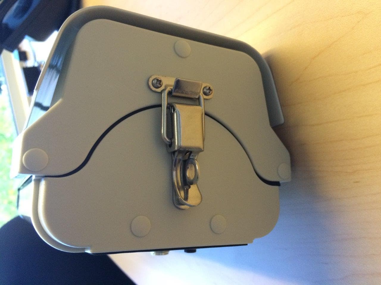
ZHXSLVC30S
Mar 23, 2015Camera
Equipment Class
DTS - Digital Transmission System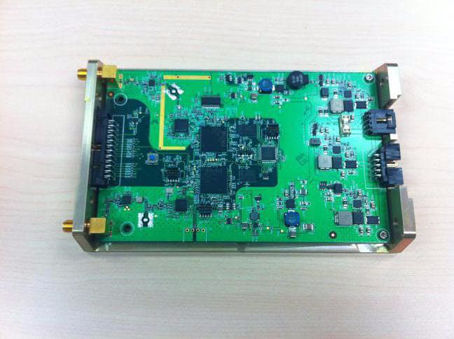
ZHX-370-00012-01
Mar 18, 2012Wireless RF Module
Equipment Class
DTS - Digital Transmission System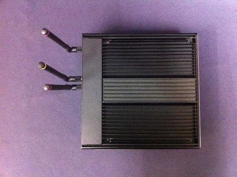
ZHXMPT2700
Jul 26, 2011Wireless Mini-Hub
Equipment Class
DTS - Digital Transmission System