ZHXSLVC30SCamera
MicroPower Technologies, Inc.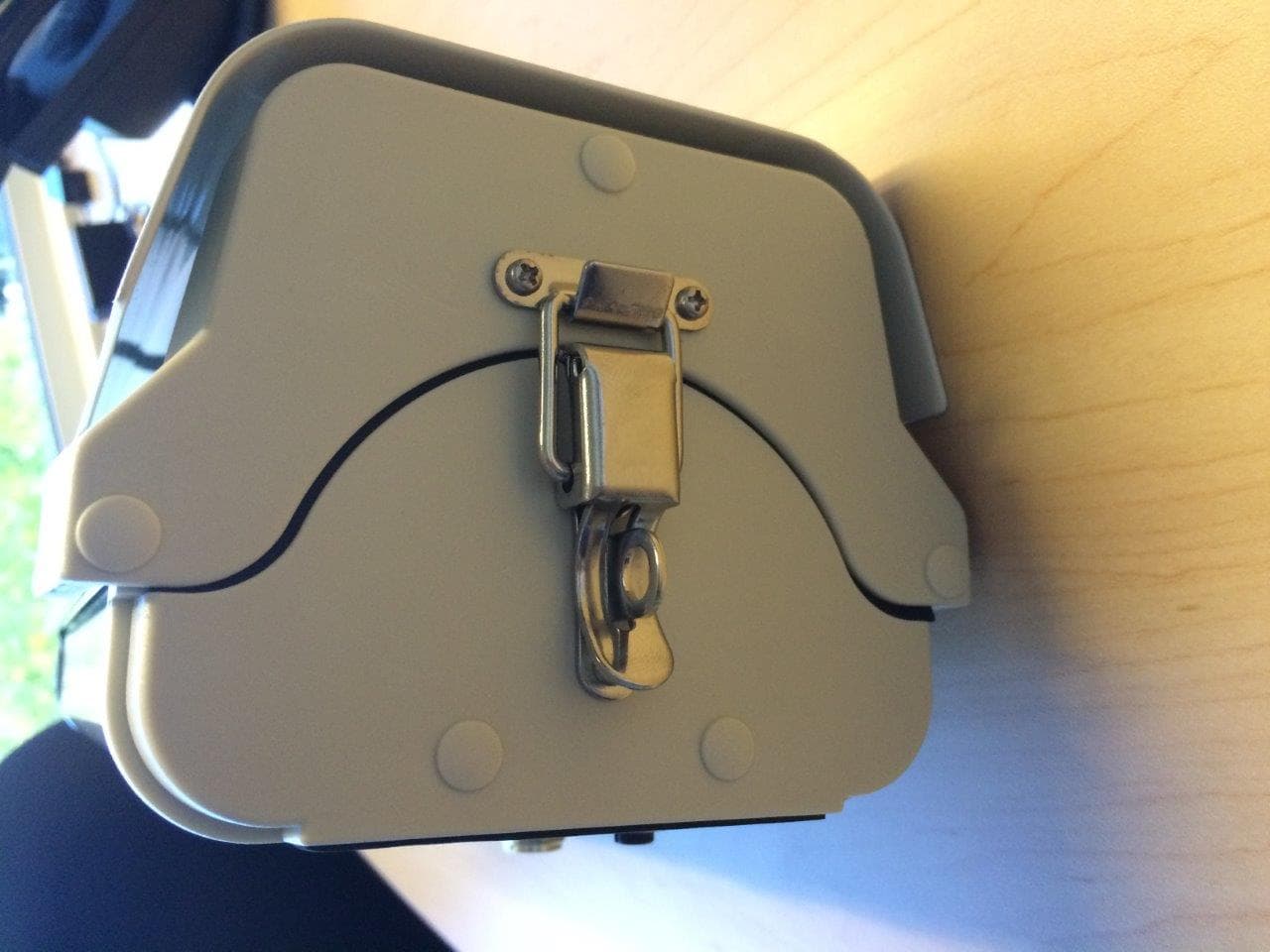
Click to zoom
Application Details
- Equipment Class
- DTS - Digital Transmission System
- Date of Grant
- Mar 23, 2015
- Application Purpose
- Original Equipment
- Date of Application
- Mar 23, 2015
- Equipment Note
- Camera
- Frequency Range
- 2417.00000000 - 2462.00000000
- Country
- United States
Documents & Files
Document Text
Text extracted from the exhibit documents filed with the FCC. Open a document above to read the original.
Users Manual
Solveil System Installation Guide A step-by-step installation guide for the MicroPower Solveil™ Solar Powered, Wireless Surveillance System SLV-C30S-1040-IR, SLV-C30S-1040, SLV-C306-1011-IR, SLV-C30S-1011 and SLV-H20HA 4350 Executive Drive, Suite 325 San Diego, CA 92121 +1-858-914-5198 www.micropower.com Version: 1.0 Product Training Experienced MicroPower installers can install cameras and equipment quickly and efficiently, however due to the highly efficient nature of the camera system, the MicroPower equipment setup differs from conventional IP surveillance devices. To quickly help System Integrator / Installers familiarize themselves with the MicroPower product line best practices and troubleshooting, MicroPower offers a variety of training options. The quickest and easiest are the short series of training videos that may be viewed on-line through the website “Partner Portal”. For more information on the training resources available, please call the customer support line or visit our website. How To Use This Guide This guide is setup in the same sequential order as a camera installation would occur. This will cover in detail all aspects of the installation and configuration of a MicroPower camera system. We highly recommend watching our series of on-line training videos. These videos will provide a strong foundation and understanding of how the system works, and ultimately making this information easier to understand. Contacting MicroPower Customer Support MicroPower’s customer support strategy is through a network of best-in-class business partners including OEMs, systems integrators and systems resellers. If your MicroPower product was purchased directly from a MicroPower business partner, that partner is the first point of contact for technical support. If the business partner cannot resolve a problem, then the partner will contact MicroPower. Web Support: http://www.micropower.com Email Support:[email protected] Toll Free Phone Support Worldwide: +1-877-536-0128 +1-858-914-5198 Press option 2 for Customer Support Fax Support – Worldwide:+1-858-947-3907 General Safety Precautions • Follow all cautions, instructions, and warnings as listed on the product and related documentation, including electro-static discharge (ESD) recommendations, physical handling advice and other best practices. • Ensure that the voltage and frequency of your power source match the voltage and frequency required by the equipment. Do not use alternative power supplies without first contacting MicroPower. • Do not attempt to modify or change the internal batteries. The battery size and voltage are calculated to match the size, voltage, and runtime required by the equipment. Modifying the battery system could result in damage to the equipment and nullification of the product warranty. • Use only the included antennas and ancillary equipment provided with the product. • Do not make mechanical or electrical modifications to equipment. MicroPower is not responsible for the safety or regulatory compliance of a modified product. • Protect your warranty. A product that has been damaged through misuse, abuse or misapplication may be determined to be out of warranty. Table of Contents Package Contents � � � � � � � � � � � � � � � � � � � � � � � � � � � � � � � � � � � � � � � � � � � � � � � � � � � � � � � � � �4 Installer Provided Parts and Infrastructure � � � � � � � � � � � � � � � � � � � � � � � � � � � � � � � � � � � � � � � � � � � � � � � � � � � � � � � � � � � � � 4 MicroPower System Overview� � � � � � � � � � � � � � � � � � � � � � � � � � � � � � � � � � � � � � � � � � � � � � � � �5 How It Works� � � � � � � � � � � � � � � � � � � � � � � � � � � � � � � � � � � � � � � � � � � � � � � � � � � � � � � � � � � � � � � � � � � � � � � � � � � � � � � � � � � � 5 Hub Connection Method� � � � � � � � � � � � � � � � � � � � � � � � � � � � � � � � � � � � � � � � � � � � � � � � � � � � � � � � � � � � � � � � � � � � � � � � � � � 6 RTSP Streaming - - - - - - - - - - - - - - - - - - - - - - - - - - - - - - - - - - - - - - - - - - - - - - - - - - - - - - - - - - - - - - - - - - - - - - - - - - - - - - 6 Getting Started - First Steps� � � � � � � � � � � � � � � � � � � � � � � � � � � � � � � � � � � � � � � � � � � � � � � � � � �7 Site Survey � � � � � � � � � � � � � � � � � � � � � � � � � � � � � � � � � � � � � � � � � � � � � � � � � � � � � � � � � � � � � � � � � � � � � � � � � � � � � � � � � � � � � 7 RF Considerations- - - - - - - - - - - - - - - - - - - - - - - - - - - - - - - - - - - - - - - - - - - - - - - - - - - - - - - - - - - - - - - - - - - - - - - - - - - - - 7 Solar Considerations- - - - - - - - - - - - - - - - - - - - - - - - - - - - - - - - - - - - - - - - - - - - - - - - - - - - - - - - - - - - - - - - - - - - - - - - - - - 8 What You Will Need � � � � � � � � � � � � � � � � � � � � � � � � � � � � � � � � � � � � � � � � � � � � � � � � � � � � � � � � � � � � � � � � � � � � � � � � � � � � � � 9 Equipment - - - - - - - - - - - - - - - - - - - - - - - - - - - - - - - - - - - - - - - - - - - - - - - - - - - - - - - - - - - - - - - - - - - - - - - - - - - - - - - - - - 9 Network Access - - - - - - - - - - - - - - - - - - - - - - - - - - - - - - - - - - - - - - - - - - - - - - - - - - - - - - - - - - - - - - - - - - - - - - - - - - - - - - 9 VMS (Video Management System) - - - - - - - - - - - - - - - - - - - - - - - - - - - - - - - - - - - - - - - - - - - - - - - - - - - - - - - - - - - - - - - - 9 Hub Installation� � � � � � � � � � � � � � � � � � � � � � � � � � � � � � � � � � � � � � � � � � � � � � � � � � � � � � � � � � �10 Hub Assembly and Installation � � � � � � � � � � � � � � � � � � � � � � � � � � � � � � � � � � � � � � � � � � � � � � � � � � � � � � � � � � � � � � � � � � � � � 10 Hub Antenna Assembly and Installation � � � � � � � � � � � � � � � � � � � � � � � � � � � � � � � � � � � � � � � � � � � � � � � � � � � � � � � � � � � � � � 12 Hub System…
Text truncated - open the document above for the full version.
ID Label/Location Info
Model: SLV-C30S Series www.micropower.com This device complies with Part 15 of the FCC rules, subject to the following conditions: 1) This device may not cause harmful interference, and 2) This device must accept any interference received, including interference that may cause undesired operation. Patents: http://www.micropower.com/about-us/legal Label Rev A FCC ID: ZHXSLVC30S Refer to User Manual
RF Exposure Info
Prediction of MPE limit at a given distance Equation from page 18 of OET Bulletin 65, Edition 97-01 where:S = power density P = power input to the antenna G = power gain of the antenna in the direction of interest relative to an isotropic radiator R = distance to the center of radiation of the antenna Maximum peak output power at antenna input terminal:22.90(dBm) Source-Based Time Averaging100.00(%) Corrected max peak output power:22.90(dBm) Maximum peak output power at antenna input terminal:194.9845(mW) Antenna gain(typical):8(dBi) Maximum antenna gain:6.309573(numeric) Prediction distance:20(cm) Prediction frequency:2440(MHz) MPE limit for uncontrolled exposure at prediction frequency:1(mW/cm^2) Power density at prediction frequency:0.244754(mW/cm^2) 2 4R PG S
Test Report
Nemko Test Report: 2015_274721_FCC15247_CAM Applicant: MicroPower Technologies 4350 Executive Dr. Suite 325 San Diego CA 92121 Equipment Under Test: SLV-C30S SERIES (E.U.T.) FCC Identifier: ZHXSLVC30S In Accordance With: FCC Part 15, Subpart C, 15.247 and Industry Canada RSS-210, Issue 8 Digital Transmission Systems Tested By: Nemko USA Inc. 2210 Faraday Ave. Suite 150 Carlsbad, CA 92008 TESTED BY: DATE: 16 January 2015 David Light, Wireless Engineer APPROVED BY: DATE: 9 February 2015 James Morris, EMC/Wireless Manager Number of Pages: 57 Nemko USA, Inc. FCC PART 15, SUBPART C and Industry Canada RSS-210 Digital Transmission Systems EQUIPMENT: SLV-C30S SERIES Test Report No.:2015_274721_FCC15247_CAM Page 2 of 57 Table of Contents SECTION 1. SUMMARY OF TEST RESULTS 3 SECTION 2. EQUIPMENT UNDER TEST (E.U.T.) 5 SECTION 3. OCCUPIED BANDWIDTH 6 SECTION 4. MAXIMUM PEAK OUTPUT POWER 15 SECTION 5 SPURIOUS EMISSIONS AT ANTENNA 22 SECTION 6. RADIATED EMISSIONS 31 SECTION 7. PEAK POWER SPECTRAL DENSITY 37 SECTION 8. TEST EQUIPMENT LIST 44 ANNEX A - TEST DETAILS 45 ANNEX B - TEST DIAGRAMS 55 Nemko USA, Inc. FCC PART 15, SUBPART C and Industry Canada RSS-210 Digital Transmission Systems EQUIPMENT: SLV-C30S SERIES Test Report No.:2015_274721_FCC15247_CAM Page 3 of 57 Section 1. Summary of Test Results Manufacturer: MicroPower Technologies Model No.: SLV-C30S SERIES Serial No.: None General: All measurements are traceable to national standards. These tests were conducted on a sample of the equipment for the purpose of demonstrating compliance with Part 15, Subpart C, Paragraph 15.247 and Industry Canada RSS-210, Issue 8 for Digital Transmission Systems. Radiated tests were conducted is accordance with ANSI C63.10: 2013. Radiated emissions are made on an open area test site. A description of the test facility is on file with the FCC and Industry Canada. New Submission Production Unit Class II Permissive Change Pre-Production Unit THIS TEST REPORT RELATES ONLY TO THE ITEM(S) TESTED. THE FOLLOWING DEVIATIONS FROM, ADDITIONS TO, OR EXCLUSIONS FROM THE TEST SPECIFICATIONS HAVE BEEN MADE. See “ Summary of Test Data”. NVLAP Lab Code 200116-0 This report must not be used to claim product certification, approval, or endorsement by NVLAP, NIST, or any agency of the Federal Government. Nemko USA, Inc. is a NVLAP accredited laboratory. Nemko USA Inc. authorizes the above named company to reproduce this report provided it is reproduced in its entirety and for use by the company’s employees only. Any use which a third party makes of this report, or any reliance on or decisions to be made based on it, are the responsibility of such third parties. Nemko USA Inc. accepts no responsibility for damages, if any, suffered by any third party as a result of decisions made or actions based on this report. This report applies only to the items tested. Nemko USA, Inc. FCC PART 15, SUBPART C and Industry Canada RSS-210 Digital Transmission Systems EQUIPMENT: SLV-C30S SERIES Test Report No.:2015_274721_FCC15247_CAM Page 4 of 57 Summary Of Test Data NAME OF TEST PARA. NO. RESULT Powerline Conducted Emissions FCC 15.207(a) / RSS-GEN 7.2.4 NA Minimum 6 dB Bandwidth FCC 15.247(a)(2) / RSS-210 A8.2(a) Complies Maximum Peak Power Output FCC 15.247(b)(3) / RSS-210 A8.4(4) Complies Spurious Emissions (Antenna Conducted) FCC 15.247(d) / RSS-210 A8.5 Complies Spurious Emissions (Restricted Bands) FCC 15.209(a) RSS-Gen 7.2.2 Complies Peak Power Spectral Density FCC 15.247(e) / RSS-210 A8.2(b) Complies Footnotes: The EUT is powered by a solar rechargeable battery. Nemko USA, Inc. FCC PART 15, SUBPART C and Industry Canada RSS-210 Digital Transmission Systems EQUIPMENT: SLV-C30S SERIES Test Report No.:2015_274721_FCC15247_CAM Page 5 of 57 Section 2. Equipment Under Test (E.U.T.) General Equipment Information Frequency Band (MHz): 902-928 2400-2483.5 5725-5850 Operating Frequency of Test Sample: 2405 to 2480 MHz (OQPSK) 2417 to 2462 MHz (OFDM) User Frequency Adjustment: Software controlled Description of EUT The SLV-C30S SERIES camera sends video feed to remote hub. The EUT has a wideband OFDM radio and a narrow band OQPSK radio. Nemko USA, Inc. FCC PART 15, SUBPART C and Industry Canada RSS-210 Digital Transmission Systems EQUIPMENT: SLV-C30S SERIES Test Report No.:2015_274721_FCC15247_CAM Page 6 of 57 Section 3. Occupied Bandwidth NAME OF TEST: Occupied Bandwidth PARA. NO.: FCC 15.247(a)(2) RSS-210 A8.2(a) TESTED BY: David Light DATE: 17 December 2014 and 05 January 2015 Test Results: Complies. Measurement Data: See 6 dB BW plot Measured 6 dB bandwidth: 16.4 MHz (OFDM) 1.9 MHz (OQPSK) Test Conditions: 35 %RH 22 °C Measurement Uncertainty: 0.20 ms Test Equipment Used: 1036 Nemko USA, Inc. FCC PART 15, SUBPART C and Industry Canada RSS-210 Digital Transmission Systems EQUIPMENT: SLV-C30S SERIES Test Report No.:2015_274721_FCC15247_CAM Page 7 of 57 Test Data – Occupied Bandwidth - OFDM 20.8 dB Offset A Unit dBm Ref Lvl 30 dBm Ref Lvl 30 dBm RF Att 30 dB Center 2.417 GHzSpan 20 MHz2 MHz/ RBW 50 kHz VBW 200 kHz SWT 20 ms IN1 1VIEW1MA -60 -50 -40 -30 -20 -10 0 10 20 -70 30 11 Delta 1 [T1] -0.12 dB 16.35270541 MHz 1 [T1] -5.51 dBm 2.40888377 GHz 1 [T1] -0.12 dB 16.35270541 MHz Date: 5.JAN.2015 11:32:21 Nemko USA, Inc. FCC PART 15, SUBPART C and Industry Canada RSS-210 Digital Transmission Systems EQUIPMENT: SLV-C30S SERIES Test Report No.:2015_274721_FCC15247_CAM Page 8 of 57 Test Data – Occupied Bandwidth – OFDM 20.8 dB Offset A Unit dBm Ref Lvl 20 dBm Ref Lvl 20 dBm RF Att 20 dB 2 MHz/Center 2.437 GHzSpan 20 MHz RBW 50 kHz VBW 200 kHz SWT 20 ms IN1 1VIEW1MA -70 -60 -50 -40 -30 -20 -10 0 10 -80 20 11 Delta 1 [T1] 0.05 dB 16.35270541 MHz 1 [T1] -4.39 dBm 2.42888377 GHz 1 [T1] 0.05 dB 16.35270541 MHz Date: 5.JAN.2015 08:45:50 Nemko USA, Inc. FCC PART 15, SUBPART C and Industry Canada RSS-210 Digital Transmission Systems EQUIPMENT: SLV-C30S SERIES Test Report No.:2015_274721_FCC15247_CAM Page 9 of 57 Test Data – Occupied Bandwidth - OFDM 20.8 dB Offs…
Text truncated - open the document above for the full version.
Contact Information
Applicant
Brian Carlton(Manger, Hardare Development)
Test Firm
Nemko USA, Inc. - San Diego EMC DivisionJan Blomgren
[email protected]760-444-3500
Technical Specifications
| # | Rule Parts | Frequency Range | Power Output |
|---|---|---|---|
| 2 | 15C | 2.42 GHz - 2.46 GHz | 170.00 mW |
Other Applications from MicroPower Technologies, Inc.
ZHXSLVH20HA
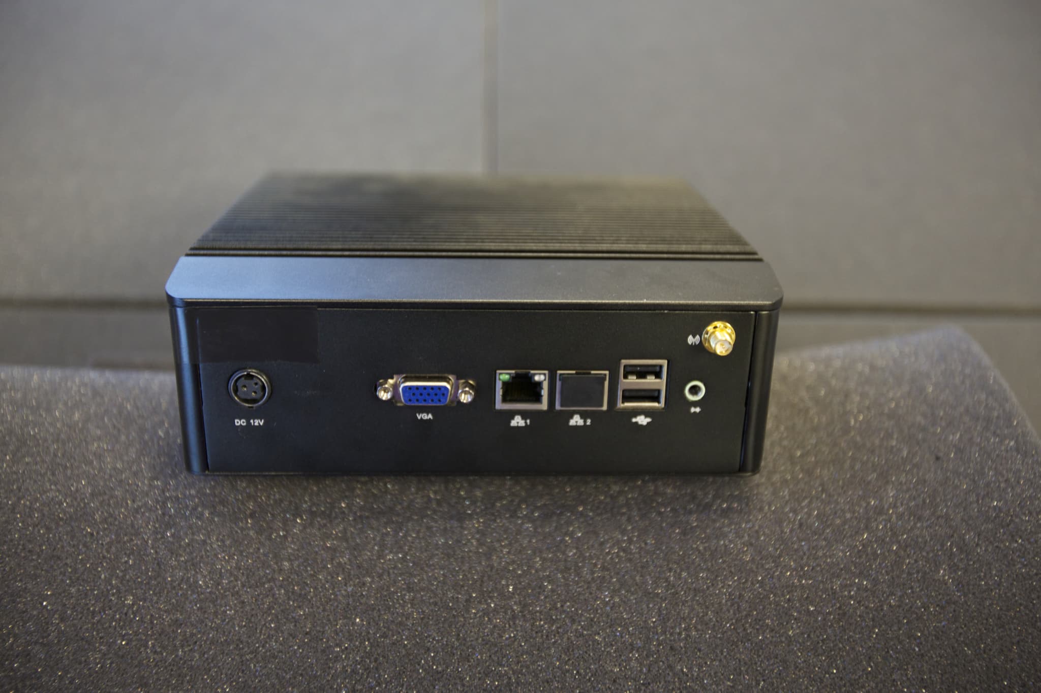
Apr 20, 2015Hub
Equipment Class
DTS - Digital Transmission System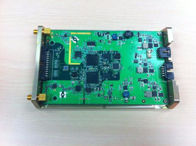
ZHX-370-00012-01
Mar 18, 2012Wireless RF Module
Equipment Class
DTS - Digital Transmission System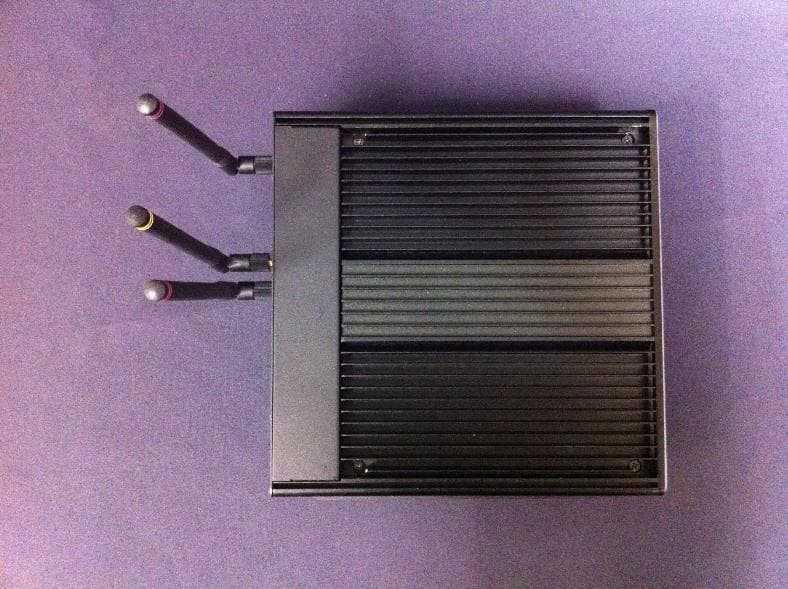
ZHXMPT2700
Jul 26, 2011Wireless Mini-Hub
Equipment Class
DTS - Digital Transmission System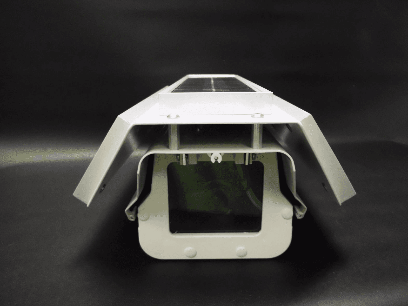
ZHXMPT2500
Jul 26, 2011Wireless Camera
Equipment Class
DTS - Digital Transmission System