ZJF-HHDCL002HHDCL002
Hong Kong China Electric Manufacture Co., Ltd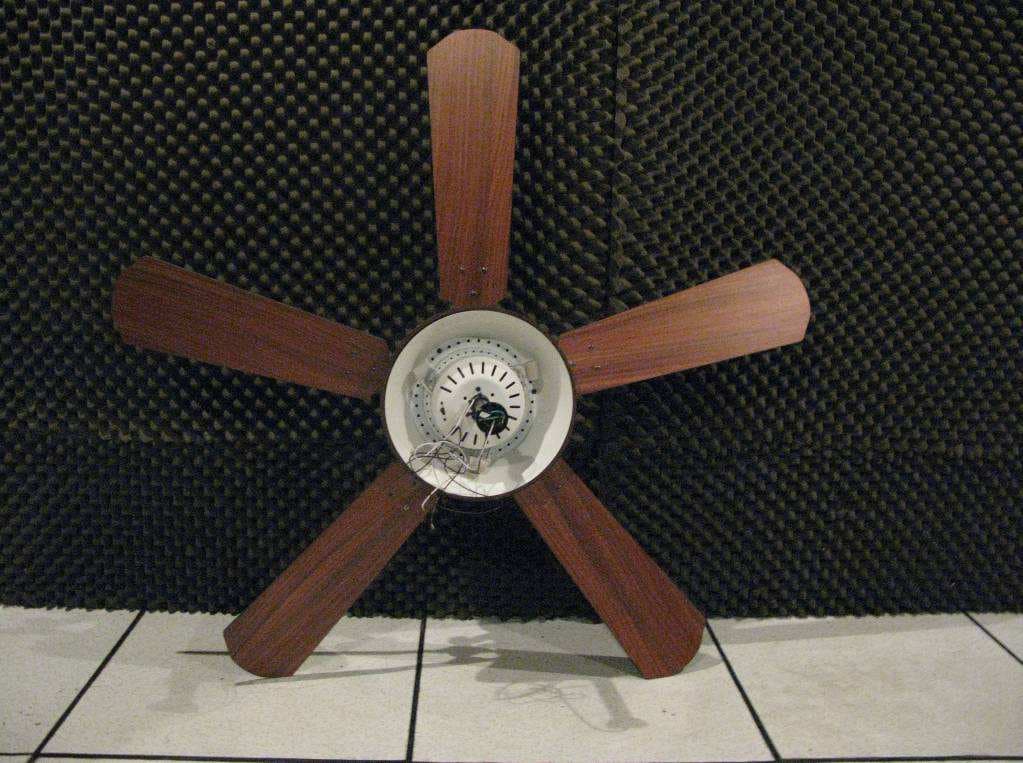
Click to zoom
Application Details
- Equipment Class
- CYY - Communications Receiver used w/Pt 15 Transmitter
- Date of Grant
- Jul 21, 2013
- Application Purpose
- Original Equipment
- Date of Application
- Jul 14, 2013
- Equipment Note
- HHDCL002
- Frequency Range
- 315.00000000 - 315.00000000
- Country
- China
Documents & Files
Document Text
Text extracted from the exhibit documents filed with the FCC. Open a document above to read the original.
Users Manual
Lowes.com/harborbreeze SAFETY INFORMATION Please read and understand this entire manual before attempting to assemble, operate, or install the product. !Before you begin installing the fan, disconnect the power by removing fuses or turning off the circuit breakers. !Make sure that all electrical connections comply with local codes, ordinances, the National "#$%&'(%)#!*+,$-!).,!/0123045/!6789::;!<('$!)!=>)#(?$,!$#$%&'(%().!+'!%+.@>#&!)!,+8(&8A+>'@$#B! wiring handbook if you are unfamiliar with installing electrical wiring. !Make sure the installation site you choose allows a minimum clearance of 7 ft. from the blades to &C$!D++'!).,!)&!#$)@&!E7!(.;!B'+F!&C$!$.,!+B!&C$!G#),$@!&+!).A!+G@&'>%&(+.; !The net weight of this fan is: 16.12 lbs. (7.31 kg). DANGER: When using an existing outlet box, make sure the outlet box is securely attached to the building structure and can support the full weight of the fan. Failure to do this can result in serious injury or death. The stability of the outlet box is essential in minimizing wobble and noise in the fan after installation is complete. WARNING: To avoid personal injury, the use of gloves may be necessary while handling fan parts with sharp edges. WARNING: Using a full-range dimmer switch to control fan speed will cause a loud humming .+(@$!B'+F!&C$!B).;!H+!'$,>%$!&C$!'(@I!+B!?'$!+'!$#$%&'(%!@C+%I-!,+!0JH!>@$!)!B>##8').K$!,(FF$'!@L(&%C! to control the fan speed. WARNING: H+!'$,>%$!&C$!'(@I!+B!?'$-!$#$%&'(%!@C+%I-!+'!M$'@+.)#!(.N>'A-!F+>.&!&C$!B).!&+!).! outlet box marked “ACCEPTABLE FOR FAN SUPPORT” and use the mounting screws provided with &C$!+>&#$&!G+O;!P+@&!+>&#$&!G+O$@!%+FF+.#A!>@$,!B+'!&C$!@>MM+'&!+B!#(KC&(.K!?O&>'$@!)'$!.+&!)%%$M&)G#$! B+'!B).!@>MM+'&!).,!F)A!.$$,!&+!G$!'$M#)%$,;!*+.@>#&!)!=>)#(?$,!$#$%&'(%().!(B!(.!,+>G&;!1$%>'$!&C$! outlet box directly to the building structure. The outlet box and its support must be able to support the moving weight of the fan (at least 35 lbs.). Do NOT use a plastic outlet box. WARNING: H+!'$,>%$!&C$!'(@I!+B!?'$-!$#$%&'(%)#!@C+%I-!+'!M$'@+.)#!(.N>'A-!L('$!%+..$%&+'@! provided with this fan are designed to accept only one 12-gauge house wire and two lead wires from the fan. If your house wire is larger than 12 gauges or there is more than one house wire to connect to the two fan lead wires, consult an electrician for the proper size wire connectors to use. WARNING: H+!'$,>%$!&C$!'(@I!+B!?'$!+'!$#$%&'(%!@C+%I-!,+!.+&!>@$!&C$!B).!L(&C!).A!@+#(,8@&)&$! speed-control device or control the fan speed with a full-range dimmer switch. WARNING: H+!'$,>%$!&C$!'(@I!+B!?'$-!$#$%&'(%!@C+%I-!+'!M$'@+.)#!(.N>'A-!,+!.+&!G$.,!&C$!G#),$! arms when installing them, balancing the blades, or cleaning the fan. Do not insert objects between the rotating fan blades. WARNING: To reduce the risk of personal injury, use only parts provided with this fan. The use of parts OTHER than those provided with this fan will void the warranty. 1 Lowes.com/harborbreeze SAFETY INFORMATION CAUTION: Read all instructions and safety information before installing your new fan. Review the accompanying assembly diagrams. CAUTION: Be sure the outlet box is properly grounded or that a ground (green or bare) wire is present. CAUTION: Carefully check all screws, bolts, and nuts on the fan motor assembly to ensure that they are secured. CAUTION: Shielded cables must be used with this unit to ensure compliance with the Class B FCC limits. WARNING:!*C).K$@!+'!F+,(?%)&(+.@!&+!&C(@!>.(&!.+&!$OM'$@@#A!)MM'+Q$,!GA!&C$!M)'&A! responsible for compliance could void the user’s authority to operate the equipment. WARNING: This equipment is a Class B digital device, pursuant to Part 15 of the FCC Rules. Limits are designed to provide reasonable protection against harmful interference in a residential installation. This equipment generates, uses, and can radiate radio frequency energy and, if not installed and used in accordance with the instructions, may cause harmful interference to radio communications. PREPARATION Before beginning the assembly of this product, ensure that all parts are present. Compare all parts with the package contents list and hardware contents list. If any part is missing or damaged, do not attempt to assemble the product. After opening the top of the carton, remove the mounting hardware package from the foam inserts, then remove the motor from the packaging and place it on a soft surface, such as a carpet, to avoid ,)F)K$!&+!&C$!?.(@C; Estimated Assembly Time: 120 minutes Tools Required for Assembly (not included): Electrical Tape, Phillips Screwdriver, Pliers, Safety Glasses, Step Ladder, and Wire Strippers Helpful Tools (not included): AC Tester Light, Tape Measure, Wiring Handbook, and Wire Cutters LAMP CONTAINS MERCURY LA BOMBILLA CONTIENE MERCURIO Manage in accordance with Spills, Disposal and Site Cleanup Requirements. In case of breakage, follow clean-up procedures provided by contacts below. Manipule según las exigencias sobre derrames, eliminación y limpieza del lugar. En caso se rompa, siga el método de limpieza proporcionado por los siguientes contactos. Hg www.epa.gov/c$cleanup 1-866-284-4010 2 Lowes.com/harborbreeze WIRING WARNING:!H+!'$,>%$!&C$!'(@I!+B!?'$-!$#$%&'(%)#!@C+%I-!+'!M$'@+.)#!(.N>'A-!L('$!%+..$%&+'@! provided with this fan are designed to accept only one 12 gauge house wire and two lead wires from the fan. If your house wire is larger then 12 gauges and there is more than one house wire to connect to the two fan lead wires, consult an electrician for the proper size wire connectors to use. WARNING: If the house wires are different colors than referred to in the following step, stop immediately. A professional electrician is recommended to determine the correct wiring scheme. CAUTION: Be sure the outlet box is properly grounded or that a ground (green or bare) wire is present. 1. Connect with supply and fan wires according to the diagram and these steps: !Connect the Green/Ground wire from the downrod and the Green/Gr…
Text truncated - open the document above for the full version.
Cover Letter(s)
QA Manager
External Photos
FCC ID: ZJF-HHDCL002 Page 1 of 2 External Picture FCC ID: ZJF-HHDCL002 Page 2 of 2
ID Label/Location Info
The label will be not removable FCC ID:ZJF-HHDCL002 This device complies with Part 15 of the FCC Rules. Operation is subject to the following two conditions: (1) this device may not cause harmful interference, and (2) this device must accept any interference received, including interference that may cause undesired operation. 65mm 35mm Label location
Internal Photos
FCC ID: ZJF-HHDCL002 Page 1 of 5 Internal Picture FCC ID: ZJF-HHDCL002 Page 2 of 5 FCC ID: ZJF-HHDCL002 Page 3 of 5 FCC ID: ZJF-HHDCL002 Page 4 of 5 FCC ID: ZJF-HHDCL002 Page 5 of 5
Test Report
FCC ID: ZJF-HHDCL002 Page 1 of 7 Test Data FCC ID: ZJF-HHDCL002 Page 2 of 7 1. Conducted Emission Phase L FCC ID: ZJF-HHDCL002 Page 3 of 7 Phase N: FCC ID: ZJF-HHDCL002 Page 4 of 7 2. Radiated Emission 30MHz-1000MHz Horiztonal Frequency Level Transd Limit Margin MHz dBμ V/m dB dBμ V/m dB 30.000000 23.80 21.0 40.0 16.2 43.607214 16.00 13.7 40.0 24.0 74.709419 15.70 9.3 40.0 24.3 117.474950 22.10 15.4 43.5 21.4 123.306613 23.20 15.4 43.5 20.3 193.286573 22.70 12.6 43.5 20.8 339.078156 20.80 16.6 46.0 25.2 455.711423 24.50 19.4 46.0 21.5 694.809619 28.20 22.2 46.0 17.8 928.076152 32.10 24.4 46.0 13.9 0 10 20 30 40 50 60 70 80 Level [dBμV/m] 30M 50M70M100M200M300M500M 700M 1G Frequency [Hz] x x x x x x x x x x x MES EZ0401-H1_red MES EZ0401-H1_pre LIM FCC 15 F 3 QP Field Strength QP FCC ID: ZJF-HHDCL002 Page 5 of 7 Vertical Frequency Level Transd Limit Margin MHz dBμ V/m dB dBμ V/m dB 33.150076 24.80 19.3 40.0 15.2 50.609218 31.32 9.8 40.0 8.7 68.742810 21.91 9.3 40.0 18.1 98.397543 27.12 15.6 43.5 16.4 151.410956 26.47 13.8 43.5 17.0 928.076152 32.10 24.4 46.0 13.9 0 10 20 30 40 50 60 70 80 Level [dBμV/m] 30M50M70M100M 200M 300M 500M 700M1G Frequency [Hz] x x MES EZ0401-V1_red MES EZ0401-V1_pre LIM FCC 15 F 3 QP Field Strength QP x x x x x FCC ID: ZJF-HHDCL002 Page 6 of 7 Above 1GHz Horizontal 0 10 20 30 40 50 60 70 80 Level [dB 礦/m] 1G2G3G4G5G Frequency [Hz] x x x x x x MES EZ0621-HH1_red MES EZ0621-HH1_pre Frequency Level Transd Limit Margin MHz dBμ V/m dB dBμ V/m dB 2555.110220 34.10 -7.2 54.0 19.9 2979.959920 35.80 -6.4 54.0 18.2 3565.130261 36.50 -4.2 54.0 17.5 4054.108216 37.80 -2.3 54.0 16.2 4911.823647 38.10 -0.4 54.0 15.9 FCC ID: ZJF-HHDCL002 Page 7 of 7 Vertical 0 10 20 30 40 50 60 70 80 Level [dB礦/m] 1G2G3G4G5G Frequency [Hz] x x x x x MES EZ0621-HV1_red MES EZ0621-HV1_pre Frequency Level Transd Limit Margin MHz dBμV/m dB dBμ V/m dB 3036.072144 34.20 -6.2 54.0 19.8 3420.841683 35.80 -4.7 54.0 18.2 4230.460922 37.30 -2.1 54.0 16.7 4871.743487 38.90 -0.5 54.0 15.1
Test Report
FCC ID: ZJF-HHDCL002 Page 2 of 20 Content SUMMARY ........................................................................................................................................................... 1 CONTENT................................................................................................................................................................ 2 1. GENERAL INFORMATION .......................................................................................................................... 3 1.1 Description of equipment under Test (EUT) ................................................................................................ 3 1.2 Description of Client .................................................................................................................................... 4 1.3 Description of Test Facility .......................................................................................................................... 5 2. TEST SPECIFICATIONS ............................................................................................................................... 6 2.1 Standards ...................................................................................................................................................... 6 2.2 Mode of operation during the test / Test peripherals used ............................................................................ 6 2.2.1 Description of operation ........................................................................................................................ 6 2.3 Instrument list ............................................................................................................................................... 7 2.4. Test Summary .............................................................................................................................................. 8 3. CONDUCTED DISTURBANCE VOLTAGE AT MAINS TERMINALS .......................................................................... 9 3.1 Limits ........................................................................................................................................................... 9 3.1.1 Limits for conducted disturbance voltage at the mains ports of class A device .................................... 9 3.1.2 Limits for conducted disturbance voltage at the mains ports of class B device .................................... 9 3.2 Test setup .................................................................................................................................................... 10 3.3 Test Setup and Test Procedure ................................................................................................................... 11 3.4 Test Protocol ............................................................................................................................................... 12 4. RADIATED EMISSION ........................................................................................................................................ 14 4.1 Radiated emission limits ............................................................................................................................. 14 4.2 Block diagram and test set up ..................................................................................................................... 15 4.3 Test Setup and Test Procedure ................................................................................................................... 16 4.4 Test Protocol ............................................................................................................................................... 17 FCC ID: ZJF-HHDCL002 Page 3 of 20 1. GENERAL INFORMATION 1.1 Description of equipment under Test (EUT) Product Name : Ceiling Fan with remote control Description of EUT : All models share same electrical construction and components, the difference is the motor type, lamp type and fan blade shape, see details below: Code representation: K=O, D or blank; "O" means can be used outdoor, "D" means can be used in damp location but not suitable for outdoor, blank means can be used indoor only. X=H, M or N, represents different hanging method. Y=80-40 , represents the diameter (inch) of the ceiling fan. A=3, 4, 5 or 6, represents the number of the blades. B means blade. CLT represents information of light kights, when no light was equipped, CLT=blank. C=1, 2, 3...6, represents the number of the lamps L means lamp. T=E, C or I, E means led Lamp, C means CFL lamp while I means incandescent lamp. (These lamps are installed by the end users and not provided by the manufacturer.) DC=DC-L15 or DC-L20; represents the motor model.(Both motors are identical except for different lamination) FCC ID: ZJF-HHDCL002 Page 4 of 20 O=M or E; "M" means mechanical type while "E" means electronic type which can be controlled by remote. We tested the sample which is electronic type with incandescent lamp and listed the worst data in the report. Model number : KXY-AB/CLTDCO (K=O, D or blank; X=H, M or N; Y=80-40; A=3, 4, 5 or 6; C=1, 2, ...6; T=E, C or I; DC=DC-L15 or DC-L20; O=M, E) Category of EUT : Class B Rating : 120V~, 60Hz, Fan motor power: 40W EUT type : Table top Floor standing Operating frequency : 315MHz Sample received date : April 22, 2013 Sample Identification No : 0130422-51-001 Date of test : April 22 ~ May 20, 2013 1.2 Description of Client Applicant : HONG KONG CHINA ELECTRIC APPLIANCE MANUFACTURE CO.,LTD. 12/F., Mongkok Harbour Centre 638 Shanghai Street, Mongkok, Kowloon, Hongkong Manufacturing site : HONG KONG CHINA ELECTRIC APPLIANCE MANUFACTURE CO.,LTD. 12/F., Mongkok Harbour Centre 638 Shanghai Street, Mongkok, Kowloon, Hongkong FCC ID: ZJF-HHDCL002 Page 5 of 20 1.3 Description of Test Facility Name Intertek Testing Service Shanghai Address Building 86, No. 1198 Qinzhou Road(North), Shanghai 200233, P.R. China Te…
Text truncated - open the document above for the full version.
Test Setup Photos
Page 1 of 3 Test Setup Page 2 of 3 1. Radiated Emission 30MHz-1000MHz Higher than 1GHz Page 3 of 3 2. Conducted Emission
Contact Information
Applicant
For Cheung(Asst. Quality Manager)
Technical Contact
Intertek Testing Services Limited ShanghaiEndman Zhao
[email protected]86 21 61278444
Buiding No.86, 1198 Qinzhou Road (North) · Shanghai · China
Test Firm
Intertek Testing Services Limited ShanghaiJonny Jing
Technical Specifications
| # | Rule Parts | Frequency Range | Power Output |
|---|---|---|---|
| 1 | 15B | 315 MHz - 315 MHz | - |
Other Applications from Hong Kong China Electric Manufacture Co., Ltd

ZJF-RT01A
Nov 02, 2015Fan Remoter
Equipment Class
DSC - Part 15 Security/Remote Control Transmitter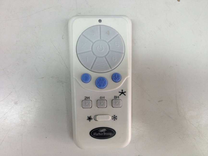
ZJF-HH002
Jun 19, 2013HH002
Equipment Class
DSC - Part 15 Security/Remote Control Transmitter
ZJF-DCM70-5B-2L
Aug 17, 2011Ceiling suspended fan
Equipment Class
CYY - Communications Receiver used w/Pt 15 Transmitter
ZJF-HH-YK-A008
Aug 03, 2011Ceiling suspended fan
Equipment Class
DSC - Part 15 Security/Remote Control Transmitter