ZLN-DGP1112BTFreedom I-Connex2 Keyboard
GREAT PLEASURE ELECTRONICS CO.,LTD
Click to zoom
Application Details
- Equipment Class
- DSS - Part 15 Spread Spectrum Transmitter
- Date of Grant
- Nov 30, 2011
- Application Purpose
- Original Equipment
- Date of Application
- Nov 30, 2011
- Equipment Note
- Freedom I-Connex2 Keyboard
- Frequency Range
- 2402.00000000 - 2480.00000000
- Country
- China
Documents & Files
Document Text
Text extracted from the exhibit documents filed with the FCC. Open a document above to read the original.
Users Manual
1 Freedom i-Connex2 Keyboard Quick Start Guide Table Of Contents Page Keyboard hardware 2 Connecting to an iPhone/iPad/iPod Touch 3 Connecting to Samsung Galaxy S and Galaxy Tab 7 Connecting to a Windows Mobile Pocket PC 9 Connecting to a Windows based Desktop/Laptop/Netbook/Tablet. 10 Trouble shooting 11 2 Your Freedom i-Connex2 Keyboard Thank you for purchasing the Freedom i-Connex2 Keyboard. Before we proceed with installing the keyboard on your phone/PDA/Pocket PC let’s take a brief look at the hardware. 1) Bluetooth Pairing Reset: Used for putting the keyboard into pairing mode when it is first paired. 2) Hinge Lock: Slide the hinge locking mechanism to the right to lock the hinge in place and stop the keyboard from folding. Slide it to the left to unlock the hinge and fold the keyboard. Please ensure that the slide mechanism is pushed fully to the left (unlocked) position before attempting to close the keyboard. 3) Pull out easel: The folding device easel pulls out completely from the keyboard to hold your phone/PDA/Pocket PC. 4) Battery Cover: Slide the battery cover upwards to open. The Freedom i-Connex2 Keyboard takes two AAA batteries. Typical AAA batteries will give up to 80 hours of continuous operation before they need to be replaced. The keyboard will automatically go into power saving mode (switch itself off) if it is left turned on for 15 minutes without any input. To take the keyboard out of power saving mode simply switch the keyboard off and then switch it back on again 5) Bluetooth Indicator Light: Flashes rapidly when in pairing/waiting to connect mode (once per second). Flashes slowly when connected (once every 8 seconds). 6) Power Warning Light: Flashes when batteries need to be replaced. 7) Power Switch: Switches the keyboard on and off. 8) SPP/HID Mode Switch: This has no function on the i-Connex2 keyboard. The i-Connex2 keyboard only uses HID mode. 9) FN (Function) Key: This key is used in combination with other keys on the keyboard to emulate buttons on the phone or to quick launch applications. Full function key combinations for each device can be found in their relevant installation instructions. Please note that FN key combinations do not work on all devices. 10) Quick Keys: These keys give quick access to commonly used controls such as volume, media playback and action button press. 3 Connecting to an iPhone/iPad/iPod touch. Please note that your device must be running the 4.0 operating system for the keyboard to be able to connect. Pairing the Keyboard 1) Turn the keyboard on and press the recessed pairing button down for 5 seconds. 2) On your iPhone, iPad or iPod touch, go to “Settings". Then from the settings screen select “General”. 3) Now under the “General” settings select “Bluetooth”. Once your device finds the keyboard select “Freedom i-Connex2 Keyboard” from the list. 4 4) Your device will now give you a 4 digit passkey. Enter this key onto the Freedom i-Connex2 and press enter to complete the pairing (also on the Freedom i-Connex2). 5) Now go back to the “Settings” page and select “Keyboard”. 5 6) Select “International Keyboards”. Now select “QWERTY” and “US International – PC”. Optional: You can also add additional keyboard layouts for other language inputs. Select the “International Keyboards” button again and then select the “Add New Keyboard” option. 7) Now your Freedom i-Connex2 keyboard will be connected. From this point forward you just need to switch the keyboard on and off when you need it. It will automatically reconnect when switched on. 6 Shortcut Keys for the iPhone and iPad Switching input language: If you have defined more than one input language (Page 5, step 6) you can quickly switch between them using the keyboard shortcut combination below. 1) Press and hold the “Menu” key. 2) Press the “Space Bar” to bring up the input language selection menu. 3) Press the “Space Bar” to toggle between input languages. 4) When the desired input language is selected release the “Menu” key. Additional Shortcut Keys Please note that some programs may not recognise all shortcut keys. Shortcut key combination Effect Menu+C Copy Selected Text Menu+V Paste Text Menu+Z Undo Menu+X Cut Selected text Shift+Cursor keys Highlight/Select Text Menu+A Select all Menu+Cursor Up Top of Page Menu+Cursor Down Bottom Of Page Double press “Home” button Open Task Switcher Hold “Home” button Open Voice Control Press “Home” button Return to Home Screen Press “Home” button when on Home Screen. Switch to “Search” bar. 7 Connecting to Samsung Galaxy S and Galaxy Tab (and other Android devices which have built in HID support). Paring the keyboard. 1) Turn the keyboard on and press the recessed pairing button down for 5 seconds. 2) On your Android Device, go to “Settings". Then from the settings screen select “Wireless and network”. 3) Now select “Bluetooth Settings”. Once your device finds the keyboard select “Freedom i-Connex2” from the list. 8 4) Your device will now give you a 6 digit passkey. Enter this key onto the Freedom i-Connex2 and press enter to complete the pairing (also on the Freedom i-Connex2). 5) Now your Freedom i-Connex2 Keyboard will be connected. From this point forward you just need to switch the Freedom i-Connex2 on and off when you need it. It will automatically reconnect when switched on. 9 Connecting to a Windows Mobile device. Phones Using HTC Touch Flow interface: 1) Turn the keyboard on and press the recessed pairing button down for 5 seconds. 2) Click on Start. 3) Click on “Settings” icon. 4) Click on “All Settings” from the left hand menu. 5) Click on the “Bluetooth” icon. 6) Click on “Menu” and select “Add Device”. The phone will now search for nearby Bluetooth devices. 7) Once it has finished searching select “Freedom i-Connex2 keyboard” from the list. 8) The phone will now give you a passkey. Enter this passkey onto the keyboard and press enter (also on the keyboard) to complete the pairing. 9) Now your Freedom i-Connex2 keyboard will be c…
Text truncated - open the document above for the full version.
Block Diagram
BT3GMD-B47P Block Diagram
External Photos
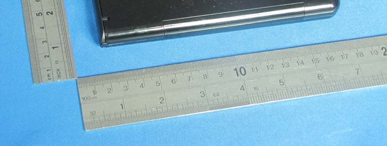
General Appearance of the EUT
ID Label/Location Info
This device complies with part 15 of the FCC Rules. Operation is subject to the following two conditions: (1) This device may not cause harmful interference, and (2) this device must accept any interference received, including interference that may cause undesired operation.
ID Label/Location Info
This device complies with part 15 of the FCC Rules. Operation is subject to the following two conditions: (1) This device may not cause harmful interference, and (2) this device must accept any interference received, including interference that may cause undesired operation.
Internal Photos
Antenna
Operational Description
GREAT PLEASURE ELECTRONICS, model: ICX-2 / Bluetooth theoretical evaluation Statement concerning compliancy with 15.247(a)1: 1 Output power and channel separation of the Bluetooth device in the different operating modes: The different operating modes (data-mode, acquisition-mode) of the Bluetooth device doesn’t influence the output power and the channel spacing. There is only one transmitter which is driven by identical input parameters concerning these two parameters. Only a different hopping sequence will be used. For this reason, the RF parameters in one op-mode is sufficient. 2 Frequency range of the Bluetooth device: The maximum frequency of the device is: 2402 – 2480 MHz. This is according the Bluetooth Core Specification V 1.0B (+ critical errata) for devices which will be operated in the USA. Other frequency ranges ( e.g. for Spain, France, Japan) which are allowed according the Core Specification must not be supported by the device. 3 Co-ordination of the hopping sequence in data mode to avoid simultaneous occupancy by multiple transmitters: Bluetooth units which want to communicate with other units must be organized in a structure called piconet. This piconet consist of max. 8 Bluetooth units. One unit is the master the other seven are the slaves. The master co-ordinates frequency occupation in this piconet for all units. As the master hop sequence is derived from it’s BD address which is unique for every Bluetooth device, additional masters intending to establish new piconets will always use different hop sequences. 4 Example of a hopping sequence in data mode: Example of a 79 hopping sequence in data mode: 40, 21, 44, 23, 42, 53, 46, 55, 48, 33, 52, 35, 50, 65, 54, 67, 56, 37, 60, 39, 58, 69, 62, 71, 64, 25, 68, 27, 66, 57, 70, 59, 72, 29, 76, 31, 74, 61, 78, 63, 01, 41, 05, 43, 03, 73, 07, 75, 09, 45, 13, 47, 11, 77, 15, 00, 64, 49, 66, 53, 68, 02, 70, 06, 01, 51, 03, 55, 05, 04 5 Equally average use of frequencies in data mode and short transmissions: The generation of the hopping sequence in connection mode depends essentially on two input values: 1).LAP/UAP of the master of the connection 2). Internal master clock. The LAP (lower address part) are the 24 LSB’s of the 48 BD_ADDRESS. The BD_ADDRESS is an unambiguous number of every Bluetooth unit. The UAP (upper address part) are the 24 MSB’s of the 48 BD_ADDRESS. The internal clock of a Bluetooth unit is derived from a free running clock which is never adjusted and is never turned off. For synchronization with other units, only the offsets are used. It has no relation to the time of the day. Its resolution is at least half the RX/TX slot length of 312.5 μs. The clock has a cycle of about one day (23h30). In most case it is implemented as 28 bit counter. For the deriving of the hopping sequence the entire LAP (24 bits), 4 LSB’s (4 bits) (Input 1) and the 27 MSB’s of the clock (Input 2) are used. With this input values different mathematical procedures (permutations, additions, XOR-operations) are performed to generate the sequence. This will be done at the beginning of every new transmission. Regarding short transmissions, the Bluetooth system has the following behavior: The first connection between the two devices is established, a hopping sequence is generated. For transmitting the wanted data, the complete hopping sequence is not used and the connection ends. The second connection will be established. A new hopping sequence is generated. Due to the fact that the Bluetooth clock has a different value, because the period between the two transmission is longer (and it cannot be shorter) than the minimum resolution of the clock (312.5 μs). The hopping sequence will always differ from the first one. 6 Receiver input bandwidth, synchronization and repeated single or multiple packets: The input bandwidth of the receiver is 1 MHz. In every connection, one Bluetooth device is the master and the other one is the slave. The master determines the hopping sequence (see chapter 5). The slave follows this sequence. Both devices shift between RX and TX time slot according to the clock of the master. Additionally the type of connection (e.g. single or multi-slot packet) is set up at the beginning of the connection. The master adapts its hopping frequency and its TX/RX timing is according to the packet type of the connection. Also, the slave of the connection uses these settings. Repeating of a packet has no influence on the hopping sequence. The hopping sequence generated by the master of the connection will be followed in any case. That means, a repeated packet will not be send on the same frequency, it is send on the next frequency of the hopping sequence 7 Dwell time in data mode The dwell time of 0.3797s within a 30 second period in data mode is independent from the packet type (packet length). The calculation for a 30 second period is a follows: Dwell time = time slot length * hop rate / number of hopping channels *30s Example for a DH1 packet (with a maximum length of one time slot) Dwell time = 625 μs * 1600 1/s / 79 * 30s = 0.3797s (in a 30s period) For multi-slot packet the hopping is reduced according to the length of the packet. Example for a DH5 packet (with a maximum length of five time slots) Dwell time = 5 * 625 μs * 1600 * 1/5 *1/s / 79 * 30s = 0.3797s (in a 30s period) This is according the Bluetooth Core Specification V 1.0B (+ critical errata) for all Bluetooth devices. Therefore, all Bluetooth devices comply with the FCC dwell time requirement in the data mode. This was checked during the Bluetooth Qualification tests. The Dwell time in hybrid mode is approximately 2.6 ms (in a 12.8s period) 8 Channel Separation in hybrid mode The nominal channel spacing of the Bluetooth system is 1 MHz independent of the operating mode. The maximum “initial carrier frequency tolerance” which is allowed for Bluetooth is f-center = 75 kHz. This was checked during the Bluetooth Qualification tests for three frequencies (2402, 2441, 2480…
Text truncated - open the document above for the full version.
Schematics
1 2 3 4 5 6 78 ABCD 8 7 6 5 4 3 2 1 D CBA Product Name Schematic Name Revision Page Date Drawing byAuthorize by ITON TECHNOLOGY Auditing by Li Mei Hai BT3GMD-B47PBT3GMD-B47P 1 of 1 1.0 20110617 RST_N G8 UART_TXD G5 UART_RXD H5 P28 B5 P29 A5 P30 E4 P31 E7 P34 B6 P35 D5 P36 C4 P37 C3 P0 F6 P1 G6 P2 H8 P3 F8 P4 H7 P5 E6 P6 F5 P7 C5 P8 F4 P9 A1 P10 D2 P11 C2 P12 B2 P13 F3 P14 D3 P15 A2 P16 C8 P17 H4 P18 C7 P19 B8 P20 A8 P21 C6 P22 G4 P23 E3 P24 A7 P25 B7 P26 A4 P27 B4 SCL E8 SDA F7 P32 D6 P33 D8 TMC G7 VSS D4 VSS1 E5 VDDO A6 VDDO1 D7 VDDC H6 VSS5 F2 VSS4 G2 VSS3 G1 VSS2 E2 XTALI32K A3 XTALO32K B3 XTALI H3 XTALO G3 RF F1 LDOIN B1 LDOOUT C1 VDDIF D1 VDDFE E1 VDDVCO H1 VDDPLL H2 BCM20730 A0 1 A1 2 A2 3 GND 4 SDA 5 SCL 6 WP 7 VCC 8 U2 24LC128 1 1 2 2 AA R7 2.7NH FB1 120@100MHZ FB2 120@100MHZ 1 3 2 4 Y1 24MHZ C1422PF C15 22PF C131.8PF C161.8PF C182.2PF C202.2PF XIN_32XOUT_32 P0 P1 P2 P3 P4 P5 P6 P7 P8 P9 P10 P11 P12 P13 P14 P15 P16 P17 P18 P19 P20 P21 P22 P23 P24 P25 P26 P27 P28 P29 P30 P31 P32 P33 P34 P35 P36 P37 SCL SDA UP_TX UP_RX REST R6 10K R3 10K R4 10K R5 10K VBAT C40.01UF C3 0.1UF VBAT SCLWPSDA R2 10K C5 0.1UF VBAT C6 2.2UF VBAT C2 1UF C1 0.1UF 1P2VC C7 0.01UF C8 10PF C9 0.01UF C19 0.01UF 1P2VC 1P2VRF R8 0R C22 2.2UF C21 2.2UF C11 1UF R13 0R 1 2 3 4 5 6 7 8 9 10 11 12 13 14 15 16 17 18 19 20 21 22 23 24 25 26 27 28 29 30 31 32 33 34 35 36 37 38 39 40 41 42 43 44 45 46 47 U1 BT3GMD-B47P GND GND P13 P8 P17 P22 UP_TX UP_RX P6 P0 P1 P5 P4 P2 P31 REST P3 SDA SCL P32 P16 P18 P19 P25 VBAT GND P20 P24 P21 P7 P29 P28 P27 P26 P36 P30 P38 P37 P15 P14 P12 P9 P23 P11 P10 GND GND C10 2.4NH
Test Report
DONGGUAN EMTEK CO., LTD. REPORT NO:KAD111118023F FCC ID: ZLN-DGP1112BT DATE: 11/29/2011 Page 1 of 37 ELECTROMAGNETIC EMISSIONS COMPLIANCE REPORT INTENTIONAL RADIATOR CERTIFICATION TO FCC PART 15 SUBPART C REQUIREMENT OF FREEDOM I-CONNEX2 KEYBOARD MODEL No.: ICX-2 BRAND NAME: N/A FCC ID: ZLN-DGP1112BT REPORT NO: KAD111118023F ISSUE DATE: November 29, 2011 Prepared for GREAT PLEASURE ELECTRONICS CO., LTD Quantang Management Area, Liaobu Town, Dongguan City, Guangdong Province Prepared by DONGGUAN EMTEK CO., LTD. No.281, Guantai Road, Nancheng District, Dongguan, Guangdong, China TEL: 86-769-22807078 FAX: 86-769-22807079 DONGGUAN EMTEK CO., LTD. REPORT NO:KAD111118023F FCC ID: ZLN-DGP1112BT DATE: 11/29/2011 Page 2 of 37 VERIFICATION OF COMPLIANCE Applicant: GREAT PLEASURE ELECTRONICS CO., LTD Quantang Management Area, Liaobu Town, Dongguan City, Guangdong Province Manufacturer: GREAT PLEASURE ELECTRONICS CO., LTD Quantang Management Area, Liaobu Town, Dongguan City, Guangdong Province Product Description: FREEDOM I-CONNEX2 KEYBOARD Brand Name: N/A Model Number: ICX-2 Serial Number: N/A File Number: KAD111118023F Date of Test: November 18, 2011 to November 28, 2011 We hereby certify that: The above equipment was tested by DONGGUAN EMTEK CO., LTD. The test data, data evaluation, test procedures, and equipment configurations shown in this report were made in accordance with the procedures given in ANSI C63.4 (2009) and the energy emitted by the sample EUT tested as described in this report is in compliance with conducted and radiated emission limits of FCC Rules Part 15.247. The test results of this report relate only to the tested sample identified in this report. Approved By Sam Lv / Q.A. Manager DONGGUAN EMTEK CO., LTD. DONGGUAN EMTEK CO., LTD. REPORT NO:KAD111118023F FCC ID: ZLN-DGP1112BT DATE: 11/29/2011 Page 3 of 37 Ta b l e o f C o n t e n t s 1. GENERAL INFORMATION ................................................................................................. 5 1.1 PRODUCT DESCRIPTION........................................................................................................................... 5 1.2 RELATED SUBMITTAL(S) / GRANT (S) ..................................................................................................... 5 1.3 TEST METHODOLOGY.............................................................................................................................. 5 1.4 SPECIAL ACCESSORIES............................................................................................................................ 5 1.5 EQUIPMENT MODIFICATIONS.................................................................................................................. 5 1.6 DESCRIPTION OF SUPPORT DEVICE......................................................................................................... 6 1.7 TEST FACILITY........................................................................................................................................ 6 2. SYSTEM TEST CONFIGURATION .................................................................................... 7 2.1 EUT CONFIGURATION............................................................................................................................. 7 2.2 EUT EXERCISE........................................................................................................................................ 7 2.3 TEST PROCEDURE.................................................................................................................................... 7 2.4 LIMITATION............................................................................................................................................. 7 2.5 CONFIGURATION OF TESTED SYSTEM................................................................................................... 11 3. SUMMARY OF TEST RESULTS ....................................................................................... 12 4. DESCRIPTION OF TEST MODES .................................................................................... 12 5. RADIATED EMISSION TEST ............................................................................................ 13 5.1 MEASUREMENT PROCEDURE................................................................................................................. 13 5.2 TEST SET-UP (BLOCK DIAGRAM OF CONFIGURATION) ....................................................................... 14 5.3 MEASUREMENT EQUIPMENT USED: ...................................................................................................... 15 5.4 MEASUREMENT RESULT........................................................................................................................ 15 5.5 RADIATED MEASUREMENT PHOTOS: ..................................................................................................... 19 6. CHANNEL SEPARATION TEST ....................................................................................... 20 6.1 MEASUREMENT PROCEDURE................................................................................................................. 20 6.2 TEST SET-UP (BLOCK DIAGRAM OF CONFIGURATION) ....................................................................... 20 6.3 MEASUREMENT EQUIPMENT USED: ...................................................................................................... 20 6.4 MEASUREMENT RESULTS:..................................................................................................................... 20 7. 20DB BANDWIDTH TEST .................................................................................................. 23 7.1 MEASUREMENT PROCEDURE................................................................................................................. 23 7.2 TEST SET-UP (BLOCK DIAGRAM OF CONFIGURATION) ....................................................................... 23…
Text truncated - open the document above for the full version.
Test Setup Photos
Radiated Emission Setup Photos
Contact Information
Applicant
Long Zhi LI(Engineer)
Technical Contact
TeleconformityMark Koop
[email protected]+31 84 8395876
Rietven 31 · Enschede, Overyssel · Netherlands
Test Firm
EMTEK (DONGGUAN) CO.,LTDSam Lv
Technical Specifications
| # | Rule Parts | Frequency Range | Power Output |
|---|---|---|---|
| 1 | 15C | 2.40 GHz - 2.48 GHz | 10.00 µW |
Other Applications from GREAT PLEASURE ELECTRONICS CO.,LTD
ZLN-DGP1201BT
Feb 13, 2012Bluetooth Keyboard
Equipment Class
DSS - Part 15 Spread Spectrum Transmitter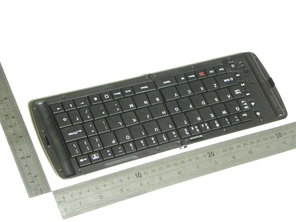
ZLN-DGP1105BT
Jun 08, 2011Blue Tooth Keyboard
Equipment Class
DSS - Part 15 Spread Spectrum Transmitter