ZLZ-ZLG600A-T2Card Reader Module
Shenzhen Mindray BIO-Medical electronics Co.,LTD.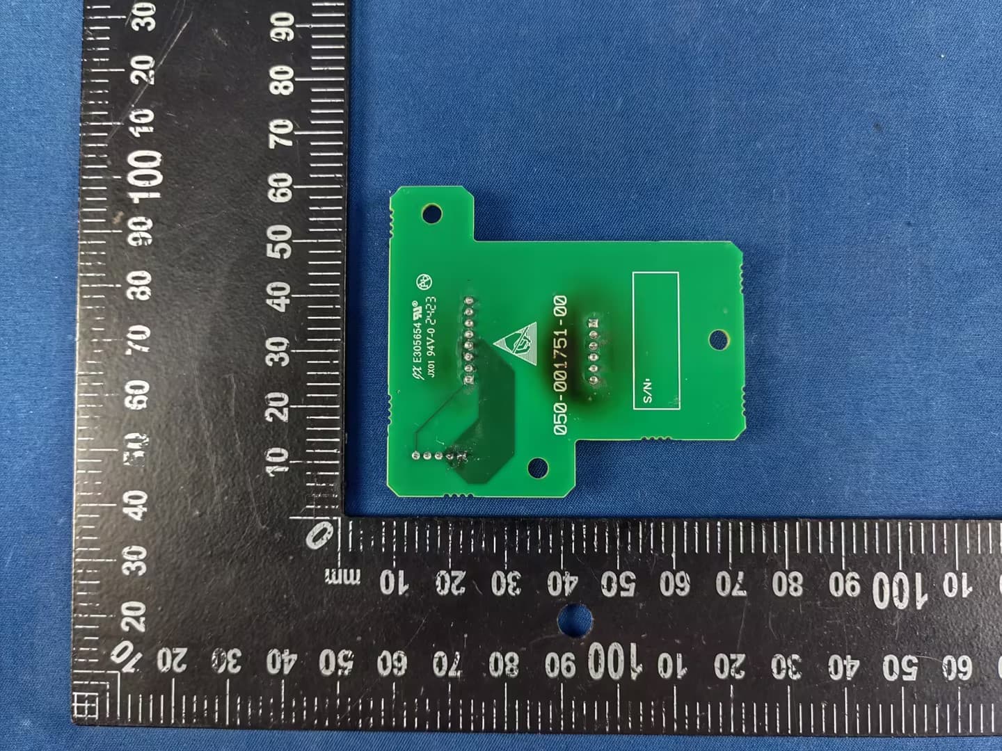
Click to zoom
Application Details
- Equipment Class
- DXX - Part 15 Low Power Communication Device Transmitter
- Date of Grant
- Jul 03, 2024
- Application Purpose
- Original Equipment
- Date of Application
- Jul 02, 2024
- Equipment Note
- Card Reader Module
- Frequency Range
- 13.56000000 - 13.56000000
- Country
- China
Documents & Files
Document Text
Text extracted from the exhibit documents filed with the FCC. Open a document above to read the original.
Users Manual
Data Sheet ZLG600A-T2 2. Operating Instructions 2.1 I/O Settings 2.1.1 Introduction to Communication Modes The communication interface is J1. This module has two communication interfaces that cannot be used simultaneously: UART and I2C interfaces. The module has three communication modes: auto detection mode, UART communication mode, and I 2 C communication mode. The auto detection mode belongs to the module factory configuration. After the module is powered on (or reset), after about 7ms initialization time, the module enters the “working mode detection” state, and the communication mode of the module is determined according to the sequence of detecting software configuration—detecting hardware configuration—auto detection mode. 1. Detecting software configuration Detecting software configuration refers to fixing the communication mode to UART or I 2 C after the module is powered on according to the configuration result of “setting equipment working mode” in equipment control commands. This setting will not lost after power-off. If configured to I 2 C mode, the module directly enters I 2 C mode; if configured to UART mode, the module directly enters UART mode, the UART baud rate is the baud rate saved inside the module, and the baud rate can be modified by “setting baud rate” in equipment control commands. 2. Detecting hardware configuration When the software configuration working mode is auto detection mode, the module does not enter a specific communication mode, but further detects the hardware configuration. The detection principle is to determine which communication mode to use based on the pin level state of the module. The J1-6, J1-7, and J1-8 pin level checks take precedence over J1-2 and J1-3. The specific definition of J1 interface is shown in Sheet 2.1. When any of J1-6, J1-7, and J1-8 pins is low, the module reads the level state every 1ms for 50 consecutive times. If the level states of J1-6, J1-7, and J1-8 are not changed, the module will enter I 2 C mode. When either of J1-2 and J1-3 pins is low, the module reads the level state every 1ms for 50 consecutive times. If the level states of J1-2 and J1-3 are not changed, the module will enter UART working mode. Sheet 2.1 Definition of Pin Pin Symbol Type Power-on state Description J1-1 /INT Output High level Interrupt output pin, open collector; In I 2 C communication mode, after the command is executed, this pin outputs low level; when responding to auto detection command and enabling interrupt output, when any card is detected, this pin outputs low level J1-2 SCL Input High level I 2 C data input pin, module with 4.7K pull-up J1-3 SDA Input/Output High level I 2 C data input/output pin, module with 4.7K pull-up J1-4 GND PWR — Negative power terminal ICC read-write modules Data Sheet ZLG600A-T2 J1-5 VCC PWR — Positive power terminal J1-6 RXD Input High level UART receiver, TTL level J1-7 TXD Output High level UART transmitter, TTL level J1-8 CON Input High level Control pin for RS-485 communication (0: input; 1: output), module auto control, TTL level Note: the square bonding pad is the 1 st pin. 3.3V module J1-5 is connected to 3.3V power supply, and 5V module J1-5 is connected to 5V power supply. 3. Auto detection mode When the software configuration and hardware configuration do not set the module as UART communication mode or I 2 C communication mode, the module will enter the auto detection mode. In this mode, both UART and I 2 C interfaces are in the receiving state, if the module detects valid baud rate from the UART communication line, the module uses UART communication; if the module receives SLA from the I 2 C bus (the factory default of SLA is 0xB2), the module uses I 2 C communication. As long as one of the interfaces receives valid data first, the module will definitely communicate with the outside world in this way and close the other interface. In auto detection mode, the UART needs to receive 0x20 twice to enter the UART communication mode. The first receiving of 0x20 is used to calculate the baud rate. The principle is to obtain the time interval of two falling edges by capturing the two falling edges in 0x20 bytes and calculate the baud rate. The second receiving of 0x20 is used to determine whether the calculated baud rate is correct. After the module successfully receives 0x20 twice, it will reply 0x06. Because this detection mechanism is easily interfered, it is not possible to send data content other than 0x20 to the module before the module calculates the correct baud rate. Otherwise, it is easy to calculate the error baud rate, causing no response to the module's command with the current baud rate. In order to ensure that the module can successfully switch to UART communication mode with the fixed baud rate from the auto detection mode, the recommended operation method is: in addition to the necessary communication interface, an additional I/O interface shall be connected to the module's EN reset pin. The module is reset every time before it is sent 0x20 twice. After resetting, there will be at least 7ms delay, and then the module can enter the auto detection mode and receive 0x20 normally. 4. UART communication mode U sers can set the module as UART communication mode after power-on by the “setting baud rate” and “setting equipment working mode” in equipment control commands. This method belongs to software configuration. For details of commands, please refer to Chapter IV. For hardware configuration UART communication mode, please refer to "detecting hardware configuration". In the UART communication mode, after the module is powered on, it will read the serial interface setting information (such as module address and baud rate) stored in the module to initialize the communication interface. The host can select the same baud rate as the module and directly perform serial interface communication with the module. 5. I 2 C communication mode Similar to the UART communication mode, users can also set th…
Text truncated - open the document above for the full version.
External Photos
Appendix- ZLG600A-T2-Photos Model ZLG600A-T2 FCC ID: ZLZ-ZLG600A-T2 Page 2 of 5 2. Photographs –Constructional Details 2.1. EUT – External View Ant.
ID Label/Location Info
Label Location
Internal Photos
Appendix- ZLG600A-T2-Photos Model ZLG600A-T2 FCC ID: ZLZ-ZLG600A-T2 Page 3 of 5 2.2. EUT – Internal View Appendix- ZLG600A-T2-Photos Model ZLG600A-T2 FCC ID: ZLZ-ZLG600A-T2 Page 4 of 5 Appendix- ZLG600A-T2-Photos Model ZLG600A-T2 FCC ID: ZLZ-ZLG600A-T2 Page 5 of 5 ======End======
RF Exposure Info
Waltek Testing Group Co., Ltd. http://www.waltek.com.cn Page 1 of 9 TEST REPORT Referen ce No. .................... : WTD24D03065704W002 FCC ID ................................ : ZLZ-ZLG600A-T2 Applicant ............................ : Shenzhen Mindray BIO-Medical electronics Co., LTD. Address .............................. : Mindray Building, Keji 12th Road South, Hi-tech Ind, Shenzhen China Manufacturer .................... : Shenzhen Mindray BIO-Medical electronics Co., LTD. Address .............................. : Mindray Building, Keji 12th Road South, Hi-tech Ind, Shenzhen China Product ............................... : Card Reader Module Model(s). ............................ : ZLG600A-T2 Standards........................... : 47 CFR Part 2 §2. 1091 Date of Receipt sample .... : 2024-03-28 Date of Test ....................... : 2024-03-28 to 2024-04-10 Date of Issue ...................... : 2024-04-10 Test Result ......................... : Pass Remarks: The re sults shown in this test report refer only to the sample(s) tested, this test report cannot be reproduced, except in full, without prior written permission of the company. The report would be invalid without specific stamp of test institute and the signatures of compiler and approver. Prepared By: Waltek Testing Group Co., Ltd. Address: No. 77, Houjie Section, Guantai Road, Houjie Town, Dongguan City, Guangdong, China Tel: +86-769-2267 6998 Fax: +86-769-2267 6828 Compiled by: Approved by: Estel Qian / Project Engineer Deval Qin /Designated Reviewer Reference No.: WTD24D03065704W002 Page 2 of 9 Waltek Testing Group Co., Ltd. http://www.waltek.com.cn 2. Contents Page 1 COVER PAGE ........................................................................................................................................... 1 2. CONTENTS ............................................................................................................................................... 2 3. REVISION HISTORY ................................................................................................................................. 3 4. GENERAL INFORMATION ....................................................................................................................... 4 4.1. GENERAL DESCRIPTION OF E.U.T.................................................................................................... 4 4.2. DETAILS OF E.U.T. ......................................................................................................................... 4 4.3. TEST FACILITY ................................................................................................................................ 5 4.4. SUBCONTRACTED ........................................................................................................................... 5 4.5. ABNORMALITIES FROM STANDARD CONDITIONS ................................................................................ 5 5. TEST SUMMARY ...................................................................................................................................... 6 6. RF EXPOSURE ......................................................................................................................................... 7 6.1. DEFINITIONS ................................................................................................................................... 7 6.2. METHOD OF EVALUATION ................................................................................................................ 7 6.3. CALCULATION FORMULA .................................................................................................................. 8 6.4. EVALUATION RESULTS .................................................................................................................... 9 Reference No.: WTD24D03065704W002 Page 3 of 9 Waltek Testing Group Co., Ltd. http://www.waltek.com.cn 3. Revision History Test Report No. Date of Receipt Sample Date of Test Date of Issue Purpose CommentApproved WTD24D03065704W002 2024-03-28 2024-03-28 to 2024-04-10 2024-04-10Original - Valid Reference No.: WTD24D03065704W002 Page 4 of 9 Waltek Testing Group Co., Ltd. http://www.waltek.com.cn 4. General Information 4.1. General Description of E.U.T. Product: Card Reader Module Model(s): ZLG600A-T2 Test Sample No.: 1-1/3 Model Description: N/A Hardware Version: N/A Software Version: N/A 4.2. Details of E.U.T. Operation Frequency: 13.56MHz±7kHz Transmitted Power: 68.20dBuV/m @3m distance Technology: ASK Antenna installation: Inductive loop coil antenna Antenna gain: N/A Note: #: The antenna gain is provided by the applicant, and the applicant should be responsible for its authenticity, WALTEK lab has not verified the authenticity of its information. Ratings: DC 5V Reference No.: WTD24D03065704W002 Page 5 of 9 Waltek Testing Group Co., Ltd. http://www.waltek.com.cn 4.3. Test Facility The test facility has a test site registered with the following organizations: ISED CAB identifier: CN0013. Test Firm Registration No.: 7760A. Waltek Testing Group Co., Ltd. Has been registered and fully described in a report filed with the Industry Canada. The acceptance letter from the Industry Canada is maintained in our files. Registration number 7760A, October 15, 2016. FCC Designation No.: CN1201. Test Firm Registration No.: 523476. Waltek Testing Group Co., Ltd. EMC Laboratory has been registered and fully described in a report filed with the (FCC) Federal Communications Commission. The acceptance letter from the FCC is maintained in our files. Registration number 523476, September 10, 2019. 4.4. Subcontracted Whether parts of tests for the product have been subcontracted to other labs: Yes No If Yes, list the related test items and lab information: Test Lab: N/A Lab address: N/A Test items: N/A 4.5. Abnormalities from Standard Conditions None. Reference No.: WTD24D03065704W002 Page 6 of 9 Waltek Testing Group Co., Ltd. htt…
Text truncated - open the document above for the full version.
Test Report
ZLG600A-ANT Datasheet Card Reader Antenna DS02040300 1.0.01 Data:2020/12/21 ————————————Overview ZLG600A-ANT is the antenna of ZLG600A Card Reader. This antenna is a coil antenna. Its operating frequency is 13.56MHz and it is used to tranceive NFC signals. —————————————— Features Operating Frequency: 13.56MHz Dimension: 34.5mm x 54mm x 1mm Type: Coil Antenna Material: FR4 —————————— Applications ◆ Finance and Commerce ◆ Software encryption ◆ Medical and Health care ◆ Traffic ticketing 理 ◆ ............ ◆ ——————— Ordering Information Model Number Operating Temperature Thickness ZLG600A-ANT -20°C ~ +80°C 1mm —————————————————————————————Antenna Image Data Sheet ©2023 Guangzhou ZHIYUAN Electronics Co., Ltd. ZLG600A-ANT Card Reader Antenna ©2023 Guangzhou ZLG Technology Corp.,Ltd. 2 DataSheet Revision History Version Date Description V1.0.00 2016/07/15 Created the document V1.0.01 2020/12/21 Modified the document template V1.0.10 2023/06/12 Update the dimension figure V1.0.20 2023/08/11 Update the document template ZLG600A-ANT Card Reader Antenna ©2023 Guangzhou ZLG Technology Corp.,Ltd. 1 DataSheet Content 1. Introduction ................................................................................................................ 1 2. Operation Instruction ................................................................................................. 2 3. Mechanical Dimension .............................................................................................. 3 4. Disclaimer .................................................................................................................. 4 ZLG600A-ANT Card Reader Antenna ©2023 Guangzhou ZLG Technology Corp.,Ltd. 1 DataSheet 1.Introduction ZLG600A-ANT is the antenna of ZLG600A Card Reader. This antenna is a coil antenna. Its operating frequency is 13.56MHz and it is used to tranceive NFC signals. ZLG600A-ANT Card Reader Antenna ©2023 Guangzhou ZLG Technology Corp.,Ltd. 2 DataSheet 2.Operation Instruction ZLG600A-ANT is easy to use. It is often printed in the other side of a ZLG600A Card Reader Module. The antenna is connected to the RF circuit by resistors and capacitors, which is shown as Figure 2. The TX1 of antenna connects to the TX1 port. And the TX2 of antenna connects to the TX2 and RX port. The GND of antenna connects to the GND of ZLG600A. Table 1 ZLG600A-ANT Parameters Product Name ZLG600A Card Reader Antenna Type Coil Antenna Model Number ZLG600A-ANT Operating Frequency 13.56MHz Dimension 34.5 x 54 x 1mm Material FR4 Operating Temperature -40~+85°C ZLG600A-ANT Card Reader Antenna ©2023 Guangzhou ZLG Technology Corp.,Ltd. 3 DataSheet 3. Mechanical Dimension The mechanical dimension of ZLG600A-ANT is shown as Figure 4. The J1 connector pin spacing is 2mm. The J1 Pad diameter is 0.8mm. The thickness of ZLG600A-ANT is 1mm. The four corner mounting holes are of symmetrical structure. The dimension of PCB antenna is shown as Figure 5. The width of antenna is 0.508mm and the spacing of antenna is 0.806mm. Tolerance of dimensions not indicated is ±0.10. Unit: mm. Figure 4 ZLG600A-ANT Dimension 32 . 95 + 0 . 20 - 0 . 15 52.40 +0.20 -0.15 R2.95 10 . 05 10 . 30 Figure 5 ZLG600A PCB Antenna Dimension ZLG600A-ANT Card Reader Antenna ©2023 Guangzhou ZLG Technology Corp.,Ltd. 4 DataSheet 4.Disclaimer About application information The application information in this document applies to the R&D of ZLG600A Card Reader Antenna. Users shall modify and verify it based on the characteristics of their products before product development. Rights to modify this document The product text information and related software described in this document are all owned by Guangzhou ZHIYUAN Electronics Co., Ltd. All these property rights are protected by the national law absolutely. Without obtaining the authorization of ZHIYUAN Electronics, other companies, organizations, agencies and individuals shall not illegally copy and use the information, or else will be subject to the severe sanctions from national laws. ZHIYUAN Electronics reserves the right to modify this document at any time without any notice. If you want to know our product and relevant information, please contact us promptly.
Test Report
Waltek Testing Group Co., Ltd. http://www.waltek.com.cn Page 1 of 25 TEST REPORT Reference No. .................... : WTD24D03065704W001 FCC ID ................................ : ZLZ-ZLG600A-T2 Applicant ............................ : Shenzhen Mindray BIO-Medical electronics Co., LTD. Address .............................. : Mindray Building, Keji 12th Road South, Hi-tech Ind, Shenzhen China Manufacturer .................... : Shenzhen Mindray BIO-Medical electronics Co., LTD. Address .............................. : Mindray Building, Keji 12th Road South, Hi-tech Ind, Shenzhen China Product ............................... : Card Reader Module Model(s). ............................ : ZLG600A-T2 Standards........................... : FCC Part 15.225 ANSI C63.10:2013 Date of Receipt sample .... : 2024-03-28 Date of Test ....................... : 2024-03-28 to 2024-04-10 Date of Issue ...................... : 2024-04-10 Test Result ......................... : Pass Remarks: The results shown in this test report refer only to the sample(s) tested, this test report cannot be reproduced, except in full, without prior written permission of the company. The report would be invalid without specific stamp of test institute and the signatures of compiler and approver. Prepared By: Waltek Testing Group Co., Ltd. Address: No. 77, Houjie Section, Guantai Road, Houjie Town, Dongguan City, Guangdong, China Tel: +86-769-2267 6998 Fax: +86-769-2267 6828 Compiled by: Approved by: Estel Qian / Project Engineer Deval Qin /Designated Reviewer Reference No.: WTD24D03065704W001 Page 2 of 25 Waltek Testing Group Co., Ltd. http://www.waltek.com.cn 2 Contents Page 1 COVER PAGE ........................................................................................................................................... 1 2 CONTENTS ............................................................................................................................................... 2 3 REVISION HISTORY ................................................................................................................................. 3 4 GENERAL INFORMATION ....................................................................................................................... 4 4.1 GENERAL DESCRIPTION OF E.U.T ................................................................................................... 4 4.2 DETAILS OF ACCESSORIES ............................................................................................................... 4 4.3 TEST MODE .................................................................................................................................... 4 4.4 TEST FACILITY ................................................................................................................................ 4 5 TEST SUMMARY ...................................................................................................................................... 5 6 EQUIPMENT USED DURING TEST ......................................................................................................... 6 6.1 EQUIPMENTS LIST ........................................................................................................................... 6 6.2 DESCRIPTION OF SUPPORT UNITS ................................................................................................... 6 6.3 MEASUREMENT UNCERTAINTY ......................................................................................................... 7 6.4 TEST EQUIPMENT CALIBRATION ....................................................................................................... 7 7 RADIATED SPURIOUS EMISSIONS ....................................................................................................... 8 7.1 EUT OPERATION ............................................................................................................................ 9 7.2 TEST SETUP ................................................................................................................................... 9 7.3 SPECTRUM ANALYZER SETUP ........................................................................................................ 10 7.4 TEST PROCEDURE ........................................................................................................................ 10 7.5 CORRECTED AMPLITUDE & MARGIN CALCULATION ......................................................................... 11 7.6 SUMMARY OF TEST RESULTS ........................................................................................................ 12 8 FREQUENCY TOLERANCE ................................................................................................................... 22 8.1 LIMIT ............................................................................................................................................ 22 8.2 TEST PROCEDURE ........................................................................................................................ 22 8.3 TEST RESULT ............................................................................................................................... 22 9 BANDWIDTH MEASUREMENT ............................................................................................................. 23 9.1 LIMIT ............................................................................................................................................ 23 9.2 TEST PROCEDURE ........................................................................................................................ 23 9.3 TEST RESULT PLOT: ..................................................................................................................... 24 10 ANTENNA REQUIREMENT ................................................................................................................... 25 11 PHOTOGRAPHS OF TEST SETUP AND EUT ...…
Text truncated - open the document above for the full version.
Test Setup Photos
Appendix- ZLG600A-T2-Photos Model ZLG600A-T2 FCC ID: ZLZ-ZLG600A-T2 Page 1 of 5 1. Test Setup photos 1.1 Photograph – Radiated Emissions For 9kHz-30MHz Test Site 2# For 30MHz-1000MHz Test Site 2#
Contact Information
Applicant
Luo jihao(Manager)
Test Firm
WALTEK TESTING GROUP CO., LTD.Joy Zhou
[email protected]0769-22676998
Technical Specifications
| # | Rule Parts | Frequency Range | Power Output |
|---|---|---|---|
| 1 | 15C | 13.56 MHz - 13.56 MHz | - |
Other Applications from Shenzhen Mindray BIO-Medical electronics Co.,LTD.
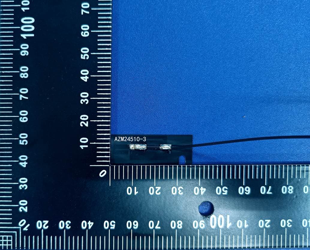
ZLZ-ALXC29
Aug 29, 2024Wireless Flat Panel Wireless Module
Equipment Class
DTS - Digital Transmission System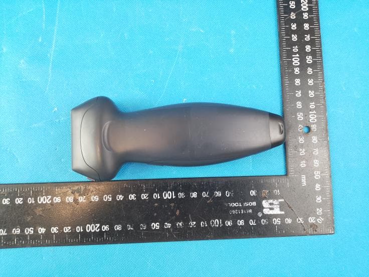
ZLZ-TEARQ
Aug 20, 2024Diagnostic Ultrasound System
Equipment Class
JAB - Part 15 Class B Digital Device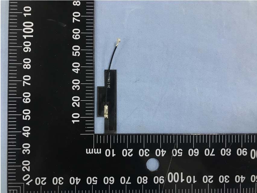
ZLZ-WLINK
May 18, 2021wireless module
Equipment Class
NII - Unlicensed National Information Infrastructure TX
ZLZ-PANLINK3
Jun 16, 2020Bluetooth module
Equipment Class
DTS - Digital Transmission System
ZLZ-WMTSAP70
Mar 22, 2020Telemetry Monitor
Equipment Class
TNB - Licensed Non-Broadcast Station Transmitter