ZOWAB-D102.4GHz WIRELESS SUBWOOFER
SHENZHEN 3NOD ELECTRONICS CO., LTD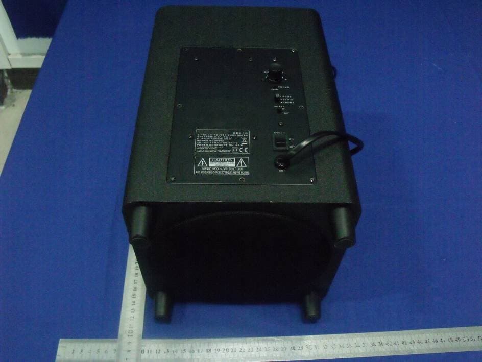
Click to zoom
Application Details
- Equipment Class
- DSS - Part 15 Spread Spectrum Transmitter
- Date of Grant
- Aug 15, 2012
- Application Purpose
- Original Equipment
- Date of Application
- Aug 15, 2012
- Equipment Note
- 2.4GHz WIRELESS SUBWOOFER
- Frequency Range
- 2412.00000000 - 2462.00000000
- Country
- China
Documents & Files
Document Text
Text extracted from the exhibit documents filed with the FCC. Open a document above to read the original.
Users Manual
GB-2 PRECAUTIONS Follow the instructions below to ensure the product is used safely and correctly. PLACEMENT Do not use the unit in environment with extreme climate. Avoid exposure to direct sun light or humid conditions. This item is designed for indoor use only. Place the unit on a flat, even surface. Do not restrict the airflow around the unit by placing it in a place well ventilated place. Avoid covering with cloth or carpet. By covering it with a cloth, or by placing it on a carpet. Do not place the unit close to heat sources. Use the apparatus only in moderate climates. Do not expose the unit to rain or splash with water. Do not place objects filled with liquids, such as vases on the unit. SAFETY When connecting and disconnecting the AC power cord, take hold of the plug and not the cord. Pulling the cord may damage it and may be dangerous. The mains plug is used as the disconnect device. The plug must be easily accessible. When you are not going to use the unit for a long period of time, disconnect the AC power cord from the AC mains outlet. Do not attempt to dissemble or modify this product. There are no user servi- ceable parts inside, and any unauthorized modifications will void the warranty. The subwoofer is designed as an added peripheral to your pre-existing AudioBulb system only. AC VOLTAGE Before use, check that the rated voltage of your unit matches your local voltage. CONDENSATION When there is condensation inside the unit, it may not function normally. Unplug the unit for 1 to 2 hours before turning the power back on, or gradually heat the room up and dry the unit before use. Ensure a minimum distance of 5 cm around the unit for sufficient ventilation. Do not cover the ventilation openings. GB-3 PRECAUTIONS The lightning flash with an arrowhead symbol within a triangle is a warning sign alerting the user to the presence of dangerous voltage inside the unit. GB-4 WHAT'S IN THE BOX 1. Wireless Subwoofer 2. Pin for pairing 3. Owner’s Manual GB-5 EASY SETUP AudioBulb wireless subwoofer 1. Bass reflex tube 2. Standby/Power LEDs (2x) 3. Speaker 4. Bass volume control 5. PAIR button 6. Crossover frequency switch 7. PHASE switch 8. POWER ON/OFF switch 9. AC cord 1 2 3 2 4 5 6 7 8 9 Connect the AC power cord to the AC mains and the other end to a wall outlet. 1. Subwoofer at a glance 2. Power Supply EASY SETUP 3. Pairing Pairing the subwoofer is essential for receiving transmission signals from the docking station. To set-up subwoofer to either zone: a. Press the PAIR located at the bottom of docking station. b. Point remote control at the docking station and press down on Zone 1 or Zone 2 button, and the connect indicator light on docking station will flash rapidly.(AUX indicator will flash when pairing Zone 2). c. Make sure Subwoofer is powered on. d. Use the pin(included) to press PAIR button on subwoofer. The blink rapidly.indicator light will e. Press PAIR button on docking station again to complete setup. Refer to AB-S10 Owner’s Manual for more information about pairing. Bass volume control Rotate the bass volume dial to adjust the volume. Crossover frequency Slide the switch to select the crossover frequency: 80, 120 or 160 Hz for different bass effect. This setting is dependent on the music content. Phase adjustment Depending on your room configuration, set the Phase Adjustment to your liking. Feel free to move the subwoofer around your house to find the optimal location. GB-6 MAINTENANCE GB-7 Care and maintenance To clean the casing, unplug the unit and wipe off dust and stains with a soft, damp cloth. Do not use benzene, thinner or similar chemicals to clean the casing. If at any time in the future you want to dispose of this product, please note that electrical products should not be disposed of with household waste. Find out where your nearest recycling centre is. Consult your local authority or retailer for more details. (Waste Electrical and Electronic Equipment Directive) HELP GB-8 Frequently Asked Questions 1. The Subwoofer does not work properly a. Make sure the unit is powered ON. b. Reset the unit by unplugging the AC power cord for a few seconds, then plugging it back in. c. Try re-pairing the Subwoofer again. 2. There is no music coming out of the Bulb, what should I do? a. Verify that there is electricity to the Bulbs. b. Double check to see that the correct music source is selected. c. Try re-pairing the bulbs with docking station, please refer to the Pairing Guide on page 14. d. Do not install these bulbs on a socket with dimmer switch. e. Make sure iPhone is UNLOCKED before docking for full compatability. 3. There is buzzing coming from the speakers, how can I eliminate it? The maximum distance between the base and the bulb should not exceed 50 to 100ft depending if there is interference, clear the air space that may be blocking the signal. It is also recommended to have clear space between other wireless products, such as wireless phones or internet routers. 4. My question is not answered, where can I get more support on this? Please call us, toll free, at 1-866-909-3550 for troubleshooting and warranty services. Please have the receipt information handy. TECHNICAL SPECIFICATIONS Power source Subwoofer AC 100-240V ~ 50/60Hz Speaker 6.5”, 4Ohm Output power -Speaker 50W (r.m.s.) Power consumption 65 W Standby power consumption < 1W Dimensions 341 (H) x 220 (W) x 220 (D) mm Weight 6.0Kg GB-9 GB-10 FCC WARNING This equipment has been tested and found to comply with the limits for a Class B digital device, pursuant to Part 15 of the FCC Rules. These limits are designed to provide reasonable protection against harmful interference in a residential installation. This equipment generates uses and can radiate radio frequency energy and, if not installed and used in accordance with the instructions, may cause harmful interference to radio communications. However, there is no guarantee that interference will not occur in a particular installation. If this equipment…
Text truncated - open the document above for the full version.
Attestation Statements
SHENZHEN 3NOD ELECTRONICS CO., LTD 3NOD High-tech Park 15#, Zhongfu Road, Tangxiayong Industrial Zone, Songgang Town, Baoan District, Shenzhen city, China. Date: July 20, 2012 We, SHENZHEN 3NOD ELECTRONICS CO., LTD, declare that this EUT (FCC ID: ZOWAB-D10) doesn’t have Ad Hoc Mode function on “non-US/Canada frequencies”. In addition, the frequency selection feature is disabled by firmware for devices marketed to the US/Canada. For DTS part of this device, only channels 1-11 will used in North America. Country code selection is disabled. Should you have any questions or comments regarding this matter, please have my best attention. Sincerely yours, Contact Person: Jiang Ming Jiang/ Engineer Company: SHENZHEN 3NOD ELECTRONICS CO., LTD E-mail: : [email protected] Phone: 86-755-29868888 Fax: 86-755-29930710 Address : 3NOD High-tech Park 15#, Zhongfu Road, Tangxiayong Industrial Zone, Songgang Town, Baoan District, Shenzhen city, China.
Cover Letter(s)
Confidentiality Request Letter Page 1 of 2 Confidentiality Request Letter Revision History Reason for Amendment (current / obsolete) From To Approved Date Initial Release (obsolete) 1.0 1.0 Nov-14-2006 Adding CFR 2.459 (obsolete) 1.0 2.0 August – 11 - 2008 Updated company template & Added text box (current) 2.0 3.0 Jan-31-2012 Confidentiality Request Letter Page 2 of 2 SHENZHEN 3NOD ELECTRONICS CO., LTD (2012-07-20) To: Federal Communications Commission Office of Engineering and Technology Equipment Authorization Division 7345 Oakland Mills Road Columbia, Maryland 21046 Subject: Permanent Confidentiality Request for FCC ID: ZOWAB-D10 We hereby request confidential treatment of information accompanying this application as outlined below: - Block diagram - Operation description - Schematic The above materials contain trade secrets and proprietary information not customarily released to the public. The public disclosure of these materials may be harmful to the applicant and provide unjustified benefits to its competitors. The applicant understands that pursuant to Section 0.457 & 0.459 of the Rules, disclosure of this application and all accompanying documentation will not be made before the date of the Grant for this application. Sincerely, Signature Jiang Ming Jiang/ Engineer E-mail: : [email protected] Phone: 86-755-29868888 Fax: 86-755-29930710 Address : 3NOD High-tech Park 15#, Zhongfu Road, Tangxiayong Industrial Zone, Songgang Town, Baoan District, Shenzhen city, China.
ID Label/Location Info
Label Location Proposed Label Location on EUT
ID Label/Location Info
A-200SW(AB-D10) 规格贴纸 2012-07-05 Speaker: 6.5”, 4 Ohm Output Power: 50 W Power Source: AC100-240V~50/60 Hz Power Consumption: 65 W FCC ID: ZOWAB-D10 Model No.: AB-D10 2.4GHz Wireless Subwoofer A-200SW(AB-D10) 规格贴纸 尺寸:L52*W30mm 材质:消银龙 过亚胶 颜色:黑底+银色字 无铅低毒 52.0 3 0 . 0 MADE IN CHINA This device complies with Part 15 of the FCC Rules. Operation is subject to the following two conditions: (1) this device may not cause harmful interference, and (2) this device must accept any interference received, including interference that may cause undesired operation.
Internal Photos
WIFI Module Antenna B Antenna A
RF Exposure Info
FCC ID : ZOWAB-D10 WIFI (Speaker device) According to §15.247(e)(i) and §1.1307(b)(1), systems operating under the provisions of this section shall be operated in a manner that ensures that the public is not exposed to radio frequency energy level in excess of the Commission’s guidelines. According to KDB 447498 (2)(a)(i) Frequency Range Low Frequency (MHz) High Frequency(MHz) Center frequency (MHz) 60/f SAR Limitation (mw) 2412 2462 2442 25 Maximum measured transmitter power: Conducted Power (dB) Max Antenna Gain (dBi) EIRP (mw) 8.88 2 12.25 Threshold at which no SAR required is 25 mW. Maximum Tx power is 12.25mw EIRP Conclusion: No SAR is required. Sincerely, Signature Jiang Ming Jiang/ Engineer E-mail: : [email protected] Phone: 86-755-29868888 Fax: 86-755-29930710 Address : 3NOD High-tech Park 15#, Zhongfu Road, Tangxiayong Industrial Zone, Songgang Town, Baoan District, Shenzhen city, China.
Test Report
SHENZHEN EMTEK CO., LTD. REPORT NO: ES120612062E FCC ID: ZOWAB-D10 DATE: 07/20/2012 Page 1 of 43 ELECTROMAGNETIC EMISSIONS COMPLIANCE REPORT INTENTIONAL RADIATOR CERTIFICATION TO FCC PART 15 SUBPART C REQUIREMENT OF 2.4GHz WIRELESS SUBWOOFER MODEL No.: A-200SW, AB-D10 FCC ID: ZOWAB-D10 Tr a d e M ar k : 3N OD , REPORT NO: ES120612062E ISSUE DATE: July 20, 2012 Prepared for SHENZHEN 3NOD ELECTRONICS CO., LTD 3NOD High-tech Park 15#, Zhongfu Road, Tangxiayong Industrial Zone, Songgang Town, Baoan District, Shenzhen city, China. Prepared by SHENZHEN EMTEK CO., LTD. Bldg 69, Majialong Industry Zone, Nanshan District, Shenzhen, Guangdong, China TEL: 86-755-26954280 FAX: 86-755-26954282 SHENZHEN EMTEK CO., LTD. REPORT NO: ES120612062E FCC ID: ZOWAB-D10 DATE: 07/20/2012 Page 3 of 43 Ta b l e o f C o n t e n t s 1. GENERAL INFORMATION ................................................................................................................................ 5 1.1 PRODUCT DESCRIPTION.................................................................................................................................... 5 1.2 RELATED SUBMITTAL(S) / GRANT(S)................................................................................................................. 5 1.3 TEST METHODOLOGY....................................................................................................................................... 6 1.4 SPECIAL ACCESSORIES...................................................................................................................................... 6 1.5 EQUIPMENT MODIFICATIONS............................................................................................................................ 6 1.6 TEST FACILITY.................................................................................................................................................. 6 2. SYSTEM TEST CONFIGURATION ................................................................................................................... 7 2.1 EUT CONFIGURATION....................................................................................................................................... 7 2.2 EUT EXERCISE................................................................................................................................................. 7 2.3 TEST PROCEDURE............................................................................................................................................. 7 2.4 CONFIGURATION OF TESTED SYSTEM............................................................................................................... 7 3. DESCRIPTION OF TEST MODES ..................................................................................................................... 9 4. SUMMARY OF TEST RESULTS....................................................................................................................... 10 5. CONDUCTED EMISSIONS TEST .................................................................................................................... 11 5.1 MEASUREMENT PROCEDURE.......................................................................................................................... 11 5.2 TEST SET-UP (BLOCK DIAGRAM OF CONFIGURATION) .................................................................................. 11 5.3 MEASUREMENT EQUIPMENT USED................................................................................................................. 11 5.4 CONDUCTED EMISSION LIMIT......................................................................................................................... 11 5.5 MEASUREMENT RESULT.................................................................................................................................. 12 5.6 CONDUCTED MEASUREMENT PHOTO.............................................................................................................. 13 6. RADIATED EMISSION TEST ........................................................................................................................... 14 6.1 MEASUREMENT PROCEDURE.......................................................................................................................... 14 6.2 TEST SET-UP (BLOCK DIAGRAM OF CONFIGURATION) .................................................................................. 14 6.3 MEASUREMENT EQUIPMENT USED................................................................................................................. 15 6.4 RADIATED EMISSION LIMIT............................................................................................................................. 15 6.5 MEASUREMENT RESULT.................................................................................................................................. 17 6.6 RADIATED MEASUREMENT PHOTOS................................................................................................................ 22 7. OCCUPIED BANDWIDTH TEST ..................................................................................................................... 24 7.1 MEASUREMENT PROCEDURE.......................................................................................................................... 24 7.2 TEST SET-UP (BLOCK DIAGRAM OF CONFIGURATION) .................................................................................. 24 7.3 MEASUREMENT EQUIPMENT USED................................................................................................................. 24 7.4 MEASUREMENT RESULTS................................................................................................................................24 8. MAXIMUM PEAK OUTPUT POWER TEST ..................................................................................................29 8.1 MEASUREMENT PROCEDURE..............................…
Text truncated - open the document above for the full version.
Test Setup Photos
Conducted Measurement Photo Radiated Measurement Photos
Contact Information
Applicant
Jiangming Jiang(Engineer)
Test Firm
EMTEK (Shenzhen) Co., Ltd.David Lee
Technical Specifications
| # | Rule Parts | Frequency Range | Power Output |
|---|---|---|---|
| 1 | 15C | 2.41 GHz - 2.46 GHz | 7.73 mW |
Other Applications from SHENZHEN 3NOD ELECTRONICS CO., LTD
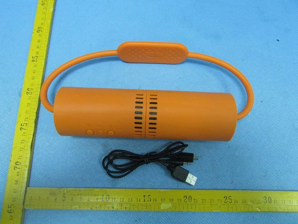
ZOWPMAD6050
Aug 19, 2013SOUNDCHUCK WIRELESS SPORT SPEAKER
Equipment Class
DSS - Part 15 Spread Spectrum Transmitter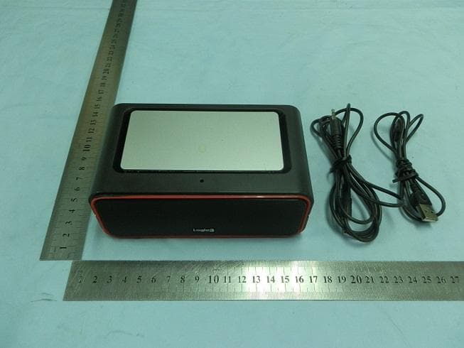
ZOWBT196
Nov 28, 20112.4G Bluetooth Speaker
Equipment Class
DSS - Part 15 Spread Spectrum Transmitter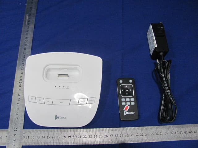
ZOWL-2017
Aug 10, 2011Wireless light Speaker System
Equipment Class
DTS - Digital Transmission System