ZP940360540999RF-ID Modul
Alfred Kaercher GmbH & Co. KG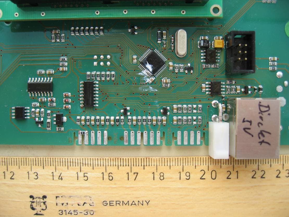
Click to zoom
Application Details
- Equipment Class
- DXX - Part 15 Low Power Communication Device Transmitter
- Date of Grant
- Mar 22, 2012
- Application Purpose
- Original Equipment
- Date of Application
- Mar 22, 2012
- Equipment Note
- RF-ID Modul
- Frequency Range
- 13.56000000 - 13.56000000
- Country
- Germany
Documents & Files
Document Text
Text extracted from the exhibit documents filed with the FCC. Open a document above to read the original.
Users Manual
Installer Instructions for Module RFID B40C/B40W/B60W The module RFID B40C/B40W/B60W consists of a control panel prepared for installation in the control panel receptacle of the Kärcher floor cleaning appliances B40C, B40W or B60W and contains a RFID reader. This RFID reader is designed for reading authorization codes for floor cleaning appliances from tags on user keys which can be inserted into a key receptacle in the control panel. The keys and the key receptacle use a design which was specifically developed for Kärcher cleaning appliances. Changes or modifications made to the equipment not explicitly approved by Alfred Kärcher GmbH & Co. KG may void the FCC / IC authorization to operate this equipment. The use of the transceiver in mobile or fixed devices other than the Kärcher floor cleaning appliances B40C, B40W or B60W is authorized taking into account the conditions listed below: • The OEM integrator has to ensure that the end user manual may not contain any information about the way to install or remove the module from the final product. • Depending on final host configuration additional authorization requirements for the non-transmitter functions on the transmitter module may be required (i.e., verification, or declaration of conformity). The OEM integrator is responsible for ensuring that after the module is installed and operational in the host, it continues to be compliant with the Part 15B unintentional radiator requirements. • The information on label and user manual for the module is required to be incorporated in the user manual of the final system. See 47 CFR15 requirements for more details (e.g. 15.19 / 15.21 / 15.101 / 15.105 / RSS-GEN / ICES) • An additional label with the text ‘Contains FCC ID: ZP940360540999’ and ‘Contains IC: 9752A-40360540999' shall be applied and visible from the outside of the end product. • The module must be installed and used in strict accordance with the manufacturer’s instructions as described in the user documentation that comes with the product. • The antenna of the module may not be removed, replaced nor modified. The antenna must not be co-located or operating in conjunction with any other antenna or transmitter. No additional antenna must be used. • The module must comply with RF exposure requirements according to CFR Part 15, RSS-210 Issue 8 Annex 2.6 and RSS-102 when it is installed in the host device. • The radio elements of the module RIFD B40C/B40W/B60W do not have the radio frequency circuitry shielded. For this reason the shielding must be provided by the module host. • The module has a microcontroller for buffered data input. The module is connected to the host by CAN-bus. • The module contains a voltage regulator for power supply. The input voltage of the module supplied by the host must be in the range from 4.25 V to 5.75 V.
External Photos
Test report no.: 1-3102/11-01-03 2012-01-18 Page 24 of 28 Annex B External photographs of the EUT Photo documentation Photo 3: Test report no.: 1-3102/11-01-03 2012-01-18 Page 25 of 28 Photo 4: Photo 5: Test report no.: 1-3102/11-01-03 2012-01-18 Page 26 of 28 Photo 6: Photo 7:
Internal Photos
Test report no.: 1-3102/11-01-03 2012-01-18 Page 24 of 28 Annex B External photographs of the EUT Photo documentation Photo 3: Test report no.: 1-3102/11-01-03 2012-01-18 Page 25 of 28 Photo 4: Photo 5: Test report no.: 1-3102/11-01-03 2012-01-18 Page 26 of 28 Photo 6: Photo 7:
Test Report
2012-01-20 Page 1 of 28 TEST REPORT Test report no.: 1-3102/11-01-03-A Testing laboratory Applicant CETECOM ICT Services GmbH Untertuerkheimer Strasse 6 – 10 66117 Saarbruecken / Germany Phone: + 49 681 5 98 - 0 Fax: + 49 681 5 98 - 9075 Internet: http://www.cetecom.com e-mail: [email protected] Accredited Testing Laboratory: The testing laboratory (area of testing) is accredited according to DIN EN ISO/IEC 17025 (2005) by the Deutsche Akkreditierungsstelle GmbH (DAkkS) The accreditation is valid for the scope of testing procedures as stated in the accreditation certificate with the registration number: D-PL-12076-01-01 Area of Testing: Radio/Satellite Communications Alfred Kärcher GmbH & Co. Alfred-Kärcher-Str. 28-40 71364 Winnenden / GERMANY Phone: +49 7195 14-0 Fax: +49 7195 14-3458 Contact: Dieter Plachke e-mail: [email protected] Phone: +49 7195 14-2374 Manufacturer Alfred Kärcher GmbH & Co. Alfred-Kärcher-Str. 28-40 71364 Winnenden / GERMANY Test standard/s 47 CFR Part 15 Title 47 of the Code of Federal Regulations; Chapter I Part 15 - Radio frequency devices RSS - 210 Issue 8 Spectrum Management and Telecommunications - Radio Standards Specification Low-power Licence-exempt Radiocommunication Devices (All Frequency Bands): Category I Equipment For further applied test standards please refer to section 3 of this test report. Test Item Kind of test item: RF-ID Modul Model name: RFID B40C/B40W/B60W FCC ID: ZP940360540999 IC: 9752A-40360540999 Frequency [MHz]: 13.56 MHz Technology tested: RFID Antenna: Integrated antenna Power Supply: 5.00 V DC Temperature Range: -20°C to 50 °C This test report is electronically signed and valid without handwriting signature. For verification of the electronic signatures, the public keys can be requested at the testing laboratory. Test report authorised: Test performed: Stefan Bös Jakob Reschke Senior Testing Manager Testing Manager Test report no.: 1-3102/11-01-03-A 2012-01-20 Page 2 of 28 1 Table of contents 1 Table of contents ............................................................................................................................................ 2 2 General information ....................................................................................................................................... 3 2.1 Notes and disclaimer .......................................................................................................................... 3 2.2 Application details ............................................................................................................................... 3 3 Test standard/s ............................................................................................................................................... 3 4 Test environment ............................................................................................................................................ 4 5 Test item .......................................................................................................................................................... 4 6 Test laboratories sub-contracted ................................................................................................................. 4 7 Summary of measurement results ............................................................................................................... 5 8 RF measurements .......................................................................................................................................... 6 8.1 Description of test setup .................................................................................................................... 6 8.1.1 Radiated measurements............................................................................................................. 6 8.1.2 Conducted measurements.......................................................................................................... 7 8.2 Additional comments .......................................................................................................................... 7 8.3 RSP100 test report cover sheet / performance test data ................................................................ 8 9 Measurement results ...................................................................................................................................... 9 9.1 Timing of the transmitter .................................................................................................................... 9 9.2 Field strength of the fundamental ................................................................................................... 10 9.3 Field strength of the harmonics and spurious ............................................................................... 13 9.4 Frequency tolerance ......................................................................................................................... 17 9.5 AC line conducted ............................................................................................................................. 18 10 Test equipment and ancillaries used for tests ................................................................................... 20 Annex A Photographs of the test setup ...................................................................................................... 22 Annex B External photographs of the EUT ................................................................................................. 24 Annex C Document history .......................................................................................................................... 27 Annex D Further information ........................................................................................................................ 27 Annex E Accreditation Certificate ..........................................................................................…
Text truncated - open the document above for the full version.
Test Setup Photos
Test report no.: 1-3102/11-01-03-A 2012-01-20 Page 22 of 28 Annex A Photographs of the test setup Photo documentation Photo 1: Test report no.: 1-3102/11-01-03-A 2012-01-20 Page 23 of 28 Photo 2:
Contact Information
Applicant
Steffen Reiser(Head of Approvals)
Test Firm
cetecom advanced GmbHGerald Schmidt
Technical Specifications
| # | Rule Parts | Frequency Range | Power Output |
|---|---|---|---|
| 1 | 15C | 13.56 MHz - 13.56 MHz | - |
Other Applications from Alfred Kaercher GmbH & Co. KG
ZP912696450999
May 07, 2024Robot Vacuum Cleaner
Equipment Class
DTS - Digital Transmission System
ZP966831810999
Jun 11, 2013Control panel with RFID reader
Equipment Class
DXT - Part 15 Low Power Transceiver, Rx Verified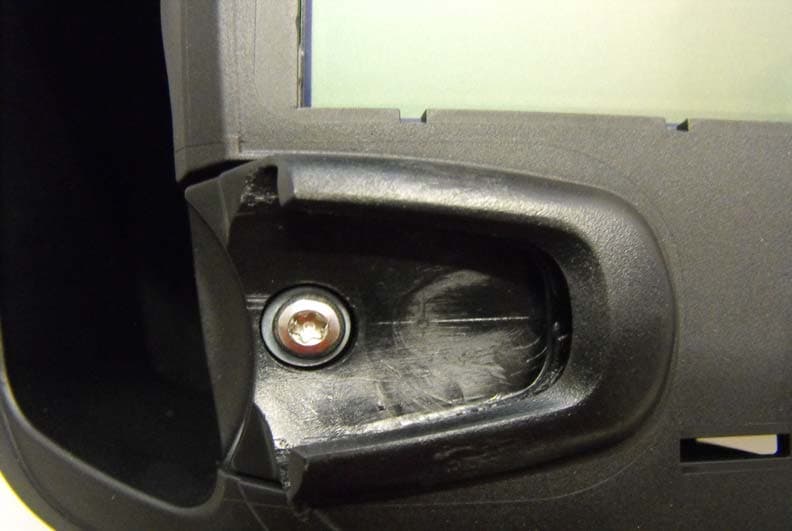
ZP940353910999
Aug 27, 2012Platine Bedienfeld B80
Equipment Class
DXX - Part 15 Low Power Communication Device Transmitter