ZR3SC-WC12LED Remote Controller Series
Signcomplex Limited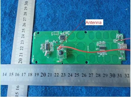
Click to zoom
Application Details
- Equipment Class
- DSC - Part 15 Security/Remote Control Transmitter
- Date of Grant
- Jul 20, 2011
- Application Purpose
- Original Equipment
- Date of Application
- Jul 20, 2011
- Equipment Note
- LED Remote Controller Series
- Frequency Range
- 433.92000000 - 433.92000000
- Company
- Signcomplex Limited
- Country
- China
Documents & Files
Document Text
Text extracted from the exhibit documents filed with the FCC. Open a document above to read the original.
Users Manual
Tel:+86-755-27608650 Fax:+86-755-27608651 [email protected] P1 www.signcomplex.com LED Remote Controller Features SC-WC12 Technical Parameter 1. Battery capacity: 800mAh 2. Standby current: <50μA 3. Standby time: 1 year 4. Battery running: 10 hours 5. Charge time: 4 hours 6. Number of Charge cycles: 500 times Dimensions Function Descriptions 1) More than 60 kinds of colors choice 2) Can show the color which the control sets 3) More than 90 kinds of scene choice 4) Auto sleep function after 60 seconds, save energy 5) Group control (one remote controller can control several controllers) 147.5mm (5.81”) 5 8 . 0 m m ( 2 . 2 8 ” ) 1 7 . 0 m m ( 0 . 6 7 ” ) The WC12 remote control is match with the WC11 and the LC-0RGB-D5 controller of Signcomplex. It can change the color, the pattern and the variation rate choice, and adjust the light, when the change suspends the light can be adjusted and so on. The whole control panel is touching method, no machinery wears which is good for the control's life. The user only needs to touch the key for the wireless control, especially suitable for lives. Tel:+86-755-27608650 Fax:+86-755-27608651 [email protected] P2 www.signcomplex.com Operation Descriptions Safety Information 1) Match the remote control address with the control First: After the controller joins RGB LED product, on the electricity, presses the “POWER” key, the controller output closure. Second: Press the “Pause” key, the controller output will be in the red light to show it have been in the state of indentifying the address. Third: Press any key of the remote controller, the controller output will be in the green light to show it has received the signal of controller. Forth: Press the power key to test whether the set is ok, if not please try again, 2) The Function description of the key Color pulley: Sliding a finger on the color pulley to choose a receptor output color of 64 colors choice. (The correct way of operation: clockwise sliding your finger on the color pulley) Function keys: MODE+, MODE- Mode selection SPEED+, SPEED- Speed selection BRT+, BRT- Brightness selection 3) Group control (one remote controller can control several controllers) When the remote is on the state of active, pressing key 1-9 then the“#”can change the remote’s address code.(For example, Once pressing 1,#,the address code of remote is 1;if pressing 1,3, #,the address code will change to 13.) First, please set a different address respectively for receptor A, B, C, D according to the step of “pair address of receptors and remotes”. (For example, set receptor A to 1, receptor B to 2, receptor C to 3 and receptor D to 4.The address can be set to a 1-digit or 2-digit optionally, but you must remember it. Please set the address again if you forget.) Second, when the receptor and remote are paired up, you can press digital key 1, then the key “#” to control the receptor A (Because the address of receptor A has been set to 1 when you pairing the address of receptors and remotes). Pressing digital key 2, then “#” is to control the receptor B, and you can control other receptors like that. Only when you switch between different receptors will need to reset the address of the remote to match the receptor. The remote will save the last address when the power is turned off. Application examples: a remote control A, B, C, D four receptors 4) In order to guarantee the life of battery, we set up 60 seconds auto dormancy function for the remote. That is, without using remote for 60 seconds, it will enter into a state of auto dormancy. To awaken it, please press the power key. (1)Please connect the USB terminal with the computer USB connector or other connector which can supply 5V power. (2)The red light will be on when in charging, if finished the light will be off. (3)The charging time should be 8h to 10h for the first fours times which will be good for the battery. www.signcomplex.com Tel:+86-755-27608650 Fax:+86-755-27608651 [email protected] P3 Signcomplex warrants this product (“Product”) against defects in material or workmanship for a period of three years from the date of purchase. If this Product is determined to be defective, Signcomplex will repair or replace the Product,at its option.This warranty does not cover cosmetic damage or damage due to acts of God, accident, misuse, abuse, negligence, commercial use, or modification of , or to any part of the Product. This warranty does not cover damage due to improper operation or maintenance, connection to improper voltage supply , or attempted repair by anyone than a facility authorized by Signcomplex to service the Product. Repair or replacement as provided under this warranty is the exclusive remedy of the customer. Signcomplex shall not be liable for any incidental or consequential damages for breach of any express or implied warranty on this Product except to the extent prohibited by applicable law, any implied warranty of merchantability or fitness for a particular purpose on this Product is limited in duration to the duration of this limited warranty. Some states do not allow the exclusion or limitation of incidental or consequential damages, or allow limitations on how long an implied warranty lasts, so the above limitations or exclusions may not apply to you. This warranty gives you specific legal rights, and you may have other rights which vary from state to state. Only Signcomplex may change, amend or modify the terms of this Limited Warranty and any such change , amendment or modification shall be in writing and is sued by Signcomplex . To obtain warranty service and shipping information call +86 755 2760 8650 or e-mail info@signcomplex .com .You must provide proof of purchase in the form of a bill of sale or receipted invoice which is evidence that the Product is within the warranty period to obtain warranty service. Consumers have legal rights under applicable national legislation governing the sale of consumer goods. Such rights are not affected b…
Text truncated - open the document above for the full version.
Block Diagram
Block Diagram
Cover Letter(s)
SCS-F18: Project and Product Certification Representative Authorization Letter Page 1 of 2 Rev 2.0 2206 Ringwood Avenue San Jose, CA 95131 Tel: 408-526-1188 Fax: 408-526-1088 Email: [email protected] Project and Product Certification Representative Authorization Letter Reason for Amendment (current / obsolete) Revision History Approved Date From To Initial Release (current) 1.0 1.0 Nov-14-2006 Revised wording (current) 1.0 2.0 Sept–25-2007 SCS-F18: Project and Product Certification Representative Authorization Letter Page 2 of 2 Rev 2.0 Signcomplex Limited (2011-07-19) To: SIEMIC, INC. 2206 Ringwood Avenue, San Jose, CA 95131 USA Dear Sir/Madam, Re: Project and Product Certification Representative Authorization Letter We, ___ Signcomplex Limited _ hereby authorize World Standardization Certification & Testing CO., LTD. to act as a Certification Body for certifying for the following project(s): (Product description: LED Remote Controller Series model name: SC-WC12, LC-0RGB-D5-04 FCC ID: ZR3SC-WC12 We affirm that between SIEMIC and ___ Signcomplex Limited __, any difference in understanding, including test plan, measurement methods, applicable standards and relevant procedures and processes have been resolved prior to commencement of testing activities. Sincerely, Client’s signature Client’s name / title: tony.j / R&D Manager Contact information / address: Yijia Industrial Park, Fuqian Road, Guanlan Town, Bao’an, Shenzhen, Guangdong, China
Cover Letter(s)
Date: 2011-07-19 To: Federal Communications Commission 7435 Oakland Mills Road Columbia, MD FCC ID: ZR3SC-WC12 To Whom It May Concern: This letter is to ascertain that SCM Microsystems, Inc. Product LED Remote Controller Series has been the units used for conducting FCC compliance testing, the DoC part will be tested by FCC recognized test lab. If you have any question or concerns, pls. contact us. Sincerely,
External Photos
EXTERIOR PHOTOGRAPHS
ID Label/Location Info
FCC ID: ZR3SC-WC12 Label Location on EUT ID Label: FCC ID: ZR3SC-WC12 This device complies with Part 15 of the FCC Rules. Operation is subject to the following two conditions: (1) this device may not cause harmful interference, and (2) this device must accept any interference received, including interference that may cause undesired operation. MADE IN CHINA
ID Label/Location Info
FCC ID: ZR3SC-WC12 Label Location on EUT ID Label: FCC ID: ZR3SC-WC12 This device complies with Part 15 of the FCC Rules. Operation is subject to the following two conditions: (1) this device may not cause harmful interference, and (2) this device must accept any interference received, including interference that may cause undesired operation. MADE IN CHINA
Internal Photos
INTERIOR PHOTOGRAPHY
Operational Description
Description The remote controller’s power supply model is 3V battery. RF Radio Frequency is 433.92Mhz. The remote controller’s main CPU is 9S08AW8, crystal frequency is 16MHz. RF part’s CPU is nRF905crystal frequency is 16Mhz. The main cpu exchange message with the RF part’s cpu by MSSP. The remote controller send commands by touching keys. 9S08AW8 send commands to nRF905 by MSSP. The nRF905 send commands by RF Radio. Then the nRF905 will wait for the receive board’s acknowledge commend. If the nRF905 received acknowledge, it will send the acknowledge to 9S08AW8. 9S08AW8 will respond by lighting the led.
Test Report
Page 1 FCC ID TEST REPORT for LED Remote Controller Series Model: SC-WC12, LC-0RGB-D5-04 Trade Mark: N/A FCC ID: ZR3SC-WC12 Test Report Number: WSCT11070311E Issued Date: July 12, 2011 Issued for Signcomplex Limited Yijia Industrial Park, Fuqian Road, Guanlan Town, Bao’an, Shenzhen, Guangdong, China Issued by: World Standardization Certification & Testing CO., LTD. Building A, Baoshi Road, Baoshi Science & Technology Park, Bao’an District, Shenzhen, Guangdong, China TEL: +86-755-26996192 FAX: +86-755-26996253 Note: This report shall not be reproduced except in full, without the written approval of World Standardization Certification& Testing CO., LTD. This document may be altered or revised by World Standardization Certification& Testing CO., LTD. personnel only, and shall be noted in the revision section of the document. The test results in the report only apply to the tested sample. Report reference No.:WSCT11070311E Issued: July 12, 2011 Revised: None TRF No.: FCC PART 15C-15.231/A0 Page 2 of 26 FCC ID: ZR3SC-WC12 This report shall not be reproduced except in full, without the written approval of World Standardization Certification & Testing CO., LTD. Revision History Rev. Issue No. Revisions Effect Page Revised By 00 WSCT11070311E Initial Issue ALL Kallen Wang Report reference No.:WSCT11070311E Issued: July 12, 2011 Revised: None TRF No.: FCC PART 15C-15.231/A0 Page 3 of 26 FCC ID: ZR3SC-WC12 This report shall not be reproduced except in full, without the written approval of World Standardization Certification & Testing CO., LTD. TABLE OF CONTENTS 1TEST RESULT CERTIFICATION .................................................................................................. 4 2 TEST RESULT SUMMARY .......................................................................................................... 5 3 EUT DESCRIPTION ..................................................................................................................... 6 4 TEST METHODOLOGY ............................................................................................................... 7 4.1 DECISION OF FINAL TEST MODE ........................................................................................................... 7 4.2 EUT SYSTEM OPERATION ..................................................................................................................... 7 5 SETUP OF EQUIPMENT UNDER TEST ...................................................................................... 8 5.1 DESCRIPTION OF SUPPORT UNITS ....................................................................................................... 8 5.2 CONFIGURATION OF SYSTEM UNDER TEST ........................................................................................ 8 6 FACILITIES AND ACCREDITATIONS ......................................................................................... 9 6.1 FACILITIES ................................................................................................................................................. 9 6.2 ACCREDITATIONS .................................................................................................................................... 9 6.3 MEASUREMENT UNCERTAINTY ............................................................................................................. 9 7 CONDUCTED EMISSION MEASUREMENT ............................................................................. 10 7.4 TEST SETUP ............................................................................................................................................ 11 7.5. TEST RESULTS ...................................................................................................................................... 11 8 RADIATED EMISSION MEASUREMENT .................................................................................. 14 8.1 LIMITS OF RADIATED EMISSION MEASUREMENT ............................................................................. 14 8.2 TEST INSTRUMENTS .............................................................................................................................. 15 8.3 TEST PROCEDURES ............................................................................................................................... 15 8.4 TEST SETUP ............................................................................................................................................ 16 8.5 TEST RESULTS ....................................................................................................................................... 17 9 20dB OCCUPIED BANDWIDTH MEASUEMENT...................................................................... 18 10 DWELL TIME MEASUREMENT ..................................................................................................... 20 11 PHOTOGRAPHS OF THE TEST CONFIGURATION ..................................................................... 23 12 PHOTOGRAPHS OF EUT .............................................................................................................. 25 Report reference No.:WSCT11070311E Issued: July 12, 2011 Revised: None TRF No.: FCC PART 15C-15.231/A0 Page 4 of 26 FCC ID: ZR3SC-WC12 This report shall not be reproduced except in full, without the written approval of World Standardization Certification & Testing CO., LTD. 1 TEST RESULT CERTIFICATION Product: LED Remote Controller Series Model: SC-WC12, LC-0RGB-D5-04 Trade Mark: N/A Applicant: Signcomplex Limited Yijia Industrial Park, Fuqian Road, Guanlan Town, Bao’an, Shenzhen, Guangdong, China Factory Signcomplex Limited Yijia Industrial Park, Fuqian Road, Guanlan Town, Bao’an, Shenzhen, Guangdong, China Tested Date: July 01~ July 12, 2011 Test Voltage: DC 5V(PC Input AC120V/60Hz) / DC 3.7V By Battery APPLICABLE STANDARDS STANDARD TEST RESULT FCC PART 15C No non-compliance noted ANSI C63.4: 2003 No non-compliance noted Note: 1. The test r…
Text truncated - open the document above for the full version.
Test Setup Photos
TEST SETUP PHOTOGRAPHY CONDUCTED EMISSION TEST (For Charging) RADIATED EMISSION TEST BELOW 1GHz (For Transmitting) RADIATED EMISSION TEST ABOVE 1GHz (For Transmitting)
Contact Information
Applicant
jing hua liu
Test Firm
World Standardization Certification&TestingCO.,LTDKelly Wu
Technical Specifications
| # | Rule Parts | Frequency Range | Power Output |
|---|---|---|---|
| 1 | 15.231 | 433.92 MHz - 433.92 MHz | - |
Other Applications from Signcomplex Limited
ZR3-DL107RG
Mar 31, 2026LED recessed downlight
Equipment Class
DTS - Digital Transmission System
ZR3-SKPT1UHL
Nov 25, 2025LED light
Equipment Class
DTS - Digital Transmission System
ZR3-SKPCBU
Jun 21, 2024LED Retrofit Downlight
Equipment Class
DTS - Digital Transmission SystemZR3-SECABCAM5G
May 13, 2024LED Camera Motion Security Lights
Equipment Class
NII - Unlicensed National Information Infrastructure TX
ZR3-SECA1020CCT2
Mar 23, 2022LED Camera Motion Security Lights
Equipment Class
DTS - Digital Transmission System