ZU3UNNECTODRIFTGSM MOBILE PHONE
Ambitio LLC, The Owner of unnecto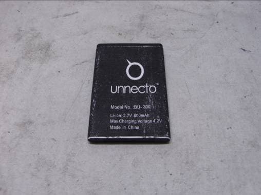
Click to zoom
Application Details
- Equipment Class
- DXX - Part 15 Low Power Communication Device Transmitter
- Date of Grant
- Sep 06, 2011
- Application Purpose
- Original Equipment
- Date of Application
- Sep 06, 2011
- Equipment Note
- GSM MOBILE PHONE
- Frequency Range
- 2402.00000000 - 2480.00000000
- Country
- United States
Documents & Files
Document Text
Text extracted from the exhibit documents filed with the FCC. Open a document above to read the original.
Users Manual
1 User Manual 2 Dear Customer, Thank you for purchasing Mobile phone. Kindly read this user manual carefully to learn about key functional characteristics and operational methods of this mobile phone. Contents I Safety and precautions................................................................3 II Cell phone outline.......................................................................4 III Getting Started.........................................................................4 IV Description of cell phone.............................................................8 V Basic operation of cell phone.......................................................10 VI Operation of menu functions.................................................................12 VII Operating instructions of English editor............................................27 VIII Application of USB storage function...............................................28 Precautions before using..........................................................28 IX My Sync...............................................................................28 X Appendix................................................................................29 Troubleshooting......................................................................29 3 I. Safety and Precautions: To use your phone safely and effectively, please read the following information before use: • Please turn off your phone when you are near a chemical plant, a gas station, an oil depot or other explosives. • To ensure safety, please use earphone during driving; Otherwise, unless emergency, make a call after parking your car by the roadside. DO NOT use the phone during driving at high speed. • Do not use your cell phone while in a plane. Please check whether Auto Power On is set or not before boarding. • Do not use your cell phone in a hospital to avoid interference with the normal operation of medical equipment which may result in a medical accident. If the cell phone is used near a pacemaker, audiphones and some medical electronic equipment, you should pay special attention that the cell phone may interfere with these devices. • Auxiliaries and accessories not provided by us are excluded from the guarantee. • Do not dismantle your cell phone by yourself. In case of a failure, please contact the service station specified by us. Only qualified personnel may install or repair this product. • The phone should be charged in the environment which is well-ventilated, and should be kept away from inflammable substances and explosives. • To avoid demagnetization, please keep your phone away from magnetic substances, such as magnetic disk, credit card, etc. • Please be sure the phone isn't exposed to any liquid. In Case this situation occurs, please remove the battery and contact the service station specified by us. • Please use your phone in the environment which is neither too hot nor too cold, do not expose you r phone in strong sunlight and in high-humidity environment. • Do not use liquid or wet cloth with strong detergent to clean your phone. • All wireless devices may be susceptible to interference, which could affect performance. • Your cell phone has photo and record functions, please use these functions following the related laws and regulations. You may violate the laws and regulations if you take photos an d record without authorization. • Do not throw, drop or hit the cell phone during use to avoid damage to the housing or the elements inside the phone. • Do not dispose the worn battery as common domestic rubbish. Please dispose the worn battery according to the specified instructions where the disposal of a worn battery is clearly specified. 4 Note: The Company won't undertake any responsibility for any consequences caused by failure to observe the above-mentioned suggestions or improper applications. If any content described in this manual goes against that of your cell phone, it is subject to the real cell phone. MAXX operates a policy of continuous development. MAXX reserves the right to make changes and improvements to any of the products described in this document without prior notice. The availability of particular products may vary by region. Please check with the MAXX dealer nearest to you. II. Cell Phone Outline: The following is the view of the phone: III. Getting Started: Installation of the SIM card: Dual-SIM operation allows the use of two services without the need to carry two phones at the same time. For example, the same handset can be used for business and private use with separate numbers and bills; or for travel. With these two SIM cards, you can use various functions of the MAXX phone. Many parameters 5 required for communications are stored in the SIM cards. Personal data, including the PIN (personal identification number) phonebook, SMS and other extra system services can also be stored in the SIM cards. Warning: DO NOT twist or scratch the SIM card and expose it to static electricity, dust or water If you lose your SIM card, please contact your network operator for help. To install your SIM cards, please turn off your MAXX phone first, remove the back cover, an d insert the SIM cards into the SIM card slots at the back of the phone. Note: The SIM card is a small object; please keep the card out of the reach of children to avoid swallowing the card by accident. Do not touch the metal surface of the SIM card and keep i t away from electromagnetism to avoid loss and damage of the data. You will not be able to connect to the network if the SIM card is damaged. Precaution: Your MAXX phone supports a memory card with capacity up to 4GB. Installation of battery: Please use the original-packaging battery and accessories. Store the battery well if it is not used. Note: Please follow the correct procedures as shown in the figure to prevent damage to the battery contact points. Charge the battery: The new battery must be fully charged and discharged for sev…
Text truncated - open the document above for the full version.
Cover Letter(s)
Ambitio LLC, The Owner of unnecto ™ FCC ID: ZU3UNNECTODRIFT POWER OF ATTORNEY August 29, 2011 Federal Communications Commission Authorization and Evaluation Division 7435 Oakland Mills Road Columbia, MD 21046 To Whom It May Concern: We, Ambitio LLC, The Owner of unnecto ™, hereby authorize Shenzhen Super Test Service Technology Co., Ltd. (Terry YANG/ Manager) on our behalf, to apply to the Federal Communications Commission on our equipment. Any and all acts carried out by Shenzhen Super Test Service Technology Co., Ltd. (Terry YANG/ Manager) on our behalf shall have the same effect as acts of our own. This authorization expires on September 31, 2011. This is to advise that we are in full compliance with the Anti-Drug Abuse Act. We, Ambitio LLC, The Owner of unnecto ™ are not subject to a denial of federal benefits pursuant to Section 5301 of the Anti-Drug Act of 1988, 21 USC853a, and no party to the application is subject to a denial of federal benefits pursuant to that section. Daniel Moy Manager Ambitio LLC, The Owner of unnecto ™ August 29, 2011
External Photos
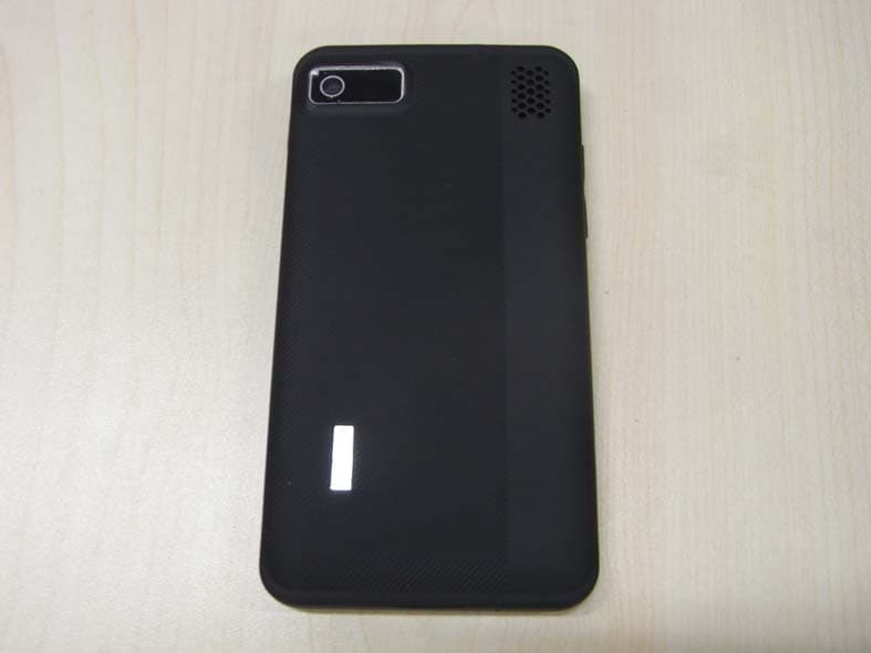
FCC ID: ZU3UNNECTODRIFT Report No.: STS110818F1 FRONT VIEW OF SAMPLE BACK VIEW OF SAMPLE FCC ID: ZU3UNNECTODRIFT Report No.: STS110818F1 LEFT VIEW OF SAMPLE RIGHT VIEW OF SAMPLE FCC ID: ZU3UNNECTODRIFT Report No.: STS110818F1 TOP VIEW OF SAMPLE BOTTOM VIEW OF SAMPLE FCC ID: ZU3UNNECTODRIFT Report No.: STS110818F1 PHOTO OF EARPHONE PHOTO OF USB CABLE FCC ID: ZU3UNNECTODRIFT Report No.: STS110818F1 PHOTO OF POWER SUPPLY PHOTO OF BATTERY
Internal Photos
FCC ID: ZU3UNNECTODRIFT Report No.: STS110818F1 INTERNAL PHOTO OF SAMPLE – 1 INTERNAL PHOTO OF SAMPLE – 2 FCC ID: ZU3UNNECTODRIFT Report No.: STS110818F1 INTERNAL PHOTO OF SAMPLE –3 INTERNAL PHOTO OF SAMPLE –4 FCC ID: ZU3UNNECTODRIFT Report No.: STS110818F1 INTERNAL PHOTO OF POWER SUPPLY-1 INTERNAL PHOTO OF POWER SUPPLY-2
Operational Description
1/2 Operation Description OPERATIONAL DESCRIPTION APPLICANT:Ambitio LLC, The Owner of unnecto ™ Manufacturer: Gold Sun Group LTD FCC ID: ZU3UNNECTODRIFT Instruction Book: Users Manual Frequency Range GSM Transmit Frequency Band: 824.2-848.8 MHz Receive Frequency Band: 849.2-893.8 MHz Transmit Frequency Band: 1850.2-1909.8 MHz Receive Frequency Band: 1930.2-1989.8 MHz Specific Operating Power Range: Power Class 1; Power Control Level 0 +30dBm +2.0dB/-2.0dB Power Control Level 1 +28dBm +3.0dB/-3.0dB Power Control Level 2 +26dBm +3.0dB/-3.0dB Power Control Level 3 +24dBm +3.0dB/-3.0dB Power Control Level 4 +22dBm +3.0dB/-3.0dB Power Control Level 5 +20dBm +3.0dB/-3.0dB Power Control Level 6 +18dBm +3.0dB/-3.0dB Power Control Level 7 +16dBm +3.0dB/-3.0dB Power Control Level 8 +14dBm +3.0dB/-3.0dB Power Control Level 9 +12dBm +4.0dB/-4.0dB Power Control Level 10 +10dBm +4.0dB/-4.0dB Power Control Level 11 +8dBm +4.0dB/-4.0dB Power Control Level 12 +6dBm +4.0dB/-4.0dB Power Control Level 13 +4dBm +4.0dB/-4.0dB Power Control Level 14 +2dBm +5.0dB/-5.0dB Power Control Level 15 +0dBm +5.0dB/-5.0dB Note; Effective radiation efficiency is –3.7dB DC Voltage and Current into the Final Amplifier Module: Supply Voltage = 5.0Vdc Supply Current = ~0.5Amp. Tune-up Procedure: Tune-up Procedure Equipment Identification: Equipment's Identification label and its intended Location are as shown in EXHIBIT Type “ID Label / Location Information” (FCC ID Nameplate), and in EXHIBIT Type “Internal Photo”(Photograph of inside) Photographs: A complete set of the Photographs showing External and Internal Views of Circuit Details and Construction are provided by from EXHIBIT Type “External Photos” and “Internal Photos”. Accessories: Accessories 2/2 Operation Description Figure 1.2: Terminal Components (Accessories) Technical Descriptions TX synthesizer uses an Offset-PLL circuit. The Offset-PLL circuit consists of PLL-IC and TX_VCO and loop filter. Reference frequency of the above synthesizers is 26MHz and generated by VCTCXO. Control signal is sent from Baseband section and keeps frequency stability. TX IQ signal is input from Baseband section to MT6235, The Bluetooth signal is input form MT6601 and FM signal is input form TLG1120 section to MT6235. TX IQ signal is applied to the quadrature up-converter, and the up-converter LO signal is generated from the transceiver VCO within MT6139B. This up-converter translates the GMSK-modulated signal to an intermediate frequency (IF) that forms one input to a frequency/phase detector circuit. This IF signal is the reference input to an Offset-PLL circuit. The feedback path of this Offset-PLL circuit includes a down-conversion from the RF output frequency range to the IF range. The two inputs to this down-conversion mixer are formed the TX_VCO output and the LO generation circuits. The mixer output is the offset feedback signal that forms the variable input to a frequency/phase detector circuit. The detector compares its variable input to its reference input and generates an error signal that is low-pass filtered by the loop filter and applied to TX_VCO to force the RF frequency in the direction that minimizes errors. The TX_VCO output passes PA, Antenna SW, Coaxial connector with switch and emitted from embedded antenna. Digital Modulation: Analog speech produced by a microphone is encoded to digital PCM samples using a CODEC. The PCM samples are passed to a Vocoder for AMR (Advanced Multi Rate) encoding, to compress the speech samples. The encoding rate is determined by the Vocoder which formats the speech samples as data packets. A new data packet with data rate information is read by the microprocessor every 20 ms. The speech CODEC becomes AMR, FR(Full Rate), EFR(Enhanced FR) and HR(Half Rate). The microprocessor then sends the data packet to the transmit subsystem, and passed DAC to covert analog signal. I/Q base band signal is filtered and is inputted into 6M4003 containing quadrature phase modulator. Battery AC Charger
Test Report
FCC 47 CFR PART 15 SUBPART C TEST REPORT For Applicant: Ambitio LLC, The Owner of unnecto ™ Address: 1315 N.W 98th ct Suite 13 United States Product Name: GSM Mobile Phone Model Name: U-300-2 Brand Name: unnecto ™ FCC ID: ZU3UNNECTODRIFT Report No.: STS110818F2 Date of Issue: August. 27, 2011 Issued by : Shenzhen Super Test Service Technology Co., Ltd. Address : No.5, Langshan 2nd Rd., North Hi-Tech Industrial park, Nanshan, Shenzhen, Guangdong, China Tel : 86-755-2795 8522 Fax : 86-755-2795 8022 The report consists 38 pages in total. It may be duplicated completely for legal use with the approval of the applicant. It should not be reproduced except in full, without the written approval of our laboratory. The client should not use it to claim product endorsement by STS. The test results in the report only apply to the tested sample. The test report shall be invalid without all the signatures of testing engineers, reviewer and approver. FCC ID: ZU3UNNECTODRIFT Report No.: STS110818F2 Page 2 of 38 TABLE OF CONTENTS 1. VERIFICATION OF CONFORMITY ............................................................................................................... 3 2. GENERAL INFORMATION ............................................................................................................................ 4 2.1 Product Information ...................................................................................................................................... 4 2.2 Objective ...................................................................................................................................................... 5 2.3 Test Standards and Results .......................................................................................................................... 5 2.4 Environmental Conditions............................................................................................................................. 5 3. TEST FACILITY.............................................................................................................................................. 6 3.1TEST FACILITY............................................................................................................................................. 6 3.2 GENERAL TEST PROCEDURES ................................................................................................................ 6 3.3 FCC PART 15.205 RESTRICTED BANDS OF OPERATIONS..................................................................... 7 4. SETUP OF EQUIPMENT UNDER TEST ....................................................................................................... 8 4.1 SUPPORT EQUIPMENT.............................................................................................................................. 8 4.2 TEST EQUIPMENT LIST ............................................................................................................................. 9 5. 47 CFR Part 15C 15.249 Requirements....................................................................................................... 10 5.1 Spurious Emission Test .............................................................................................................................. 10 5.1.1 Requirement............................................................................................................................................ 10 5.1.2 Test Description ........................................................................................................................................11 5.1.3 Test Description ....................................................................................................................................... 12 5.1.4 Test Result ......................................................................................................................................... 13 5.2 Band Edge ................................................................................................................................................. 19 5.2.1 Requirement............................................................................................................................................ 19 5.2.2 Test Description ....................................................................................................................................... 19 5.2.3Test Result................................................................................................................................................ 19 5.3 LINE CONDUCTED EMISSION TEST ....................................................................................................... 24 5.3.1. LIMITS OF LINE CONDUCTED EMISSION TEST ................................................................................ 24 5.3.2. BLOCK DIAGRAM OF TEST SETUP..................................................................................................... 24 5.3.3. PRELIMINARY PROCEDURE OF LINE CONDUCTED EMISSION TEST ............................................ 25 5.3.4. FINAL PROCEDURE OF LINE CONDUCTED EMISSION TEST .......................................................... 25 5.3.5. TEST RESULT OF LINE CONDUCTED EMISSION TEST .................................................................... 26 APPENDIX 1 .................................................................................................................................................... 28 PHOTOGRAPHS OF TEST SETUP................................................................................................................. 28 APPENDIX 2 .................................................................................................................................................... 30 PHOTOGRAPHS OF EUT ............................................................................................................................... 30 FCC ID: ZU3UNNECTODRIFT Report No.: ST…
Text truncated - open the document above for the full version.
Test Setup Photos
FCC ID: ZU3UNNECTODRIFT Page 32 of 44 CE TEST SETUP FCC ID: ZU3UNNECTODRIFT Page 33 of 44 CONDUCTED TEST SETUP RADIATED EMISSION TEST SETUP FCC ID: ZU3UNNECTODRIFT
Contact Information
Applicant
Daniel Moy(Manager)
Test Firm
Most Technology Service Co., Ltd.Mark Wen
Technical Specifications
| # | Rule Parts | Frequency Range | Power Output |
|---|---|---|---|
| 1 | 15C | 2.40 GHz - 2.48 GHz | - |
Other Applications from Ambitio LLC, The Owner of unnecto
ZU3UNNECTOQUA
Jun 19, 20123G MOBILE PHONE-WIFI PORTION
Equipment Class
DTS - Digital Transmission System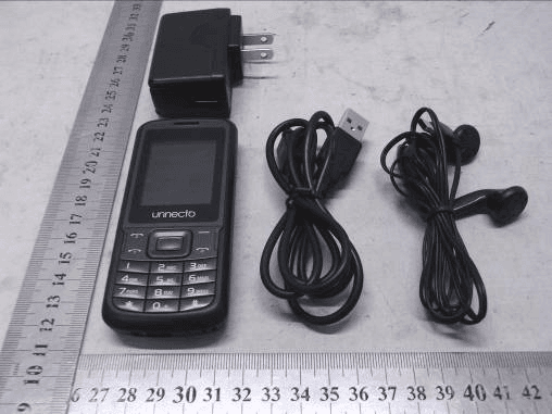
ZU3UNNECTOECOBT
Apr 02, 2012GSM MOBILE PHONE - BLUETOOTH PORTION
Equipment Class
DXX - Part 15 Low Power Communication Device Transmitter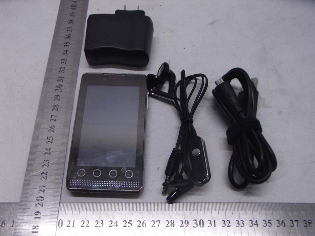
ZU3UNNECTODRONE
Feb 27, 2012GSM MOBILE PHONE-WIFI PORTION
Equipment Class
DTS - Digital Transmission System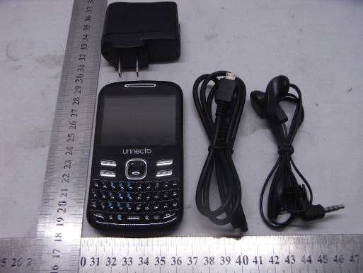
ZU3UNNECTOCURVE
Jan 24, 2012GSM MOBILE PHONE
Equipment Class
PCE - PCS Licensed Transmitter held to ear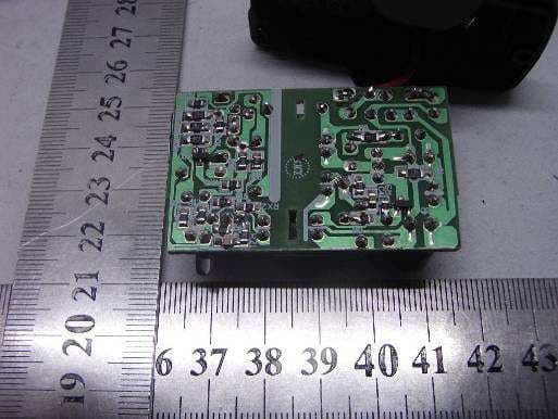
ZU3UNNECTOBLAZE
Jan 12, 2012GSM MOBILE PHONE-BLUETOOTH PORTION
Equipment Class
DXX - Part 15 Low Power Communication Device Transmitter