2A22V-DL013Desk Lamp Wireless Charger
Shenzhen DXR Electronic Technology Co., Limited (Dongguan Branch)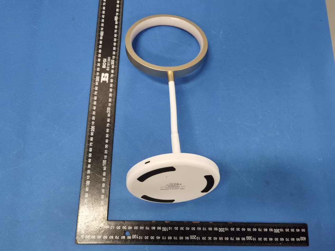
Click to zoom
Application Details
- Equipment Class
- DCD - Part 15 Low Power Transmitter Below 1705 kHz
- Date of Grant
- Jul 14, 2022
- Application Purpose
- Original Equipment
- Date of Application
- Jul 14, 2022
- Equipment Note
- Desk Lamp Wireless Charger
- Frequency Range
- 0.11150000 - 0.20500000
- Country
- China
Documents & Files
Document Text
Text extracted from the exhibit documents filed with the FCC. Open a document above to read the original.
Users Manual
1. Short press among cool light,Warm light,Neuter Mixed light,OFF Long press cycle through brightness levels 2. Wireless charging area 3. Input Input: 9V 2A Wireless output:5W,7.5W,10W Lamp power:4W Power supply connected:Blue LED on Wireless charger is charging for mobile phone:Red LED on FOD :Red LED flashing Accessories:Type C‐USB cable
Cover Letter(s)
Shenzhen DXR Electronic Technology Co., Limited (Dongguan Branch) Agent Authorization Company: Shenzhen DXR Electronic Technology Co., Limited (Dongguan Branch) Address: 4th Floor, #5 Building, #189, Yongji Industrial, Zhuweitian, Fenggang Town, Dongguan, China Product Name: Desk Lamp Wireless Charger Model Number(s): WAC-DL013, WAC-DL014, WAC-DL015, WAC-DL016 Product Description: Desk Lamp Wireless Charger We authorize MiCOM Labs Inc., 575 Boulder Court, Pleasanton, California 94566, USA, to act on our behalf on all matters concerning the certification of above named equipment. We declare that MiCOM Labs Inc. is allowed to forward all information related to the approval and certification of equipment to the regulatory agencies as required and to discuss any issues concerning the approval application. Any and all acts carried out by MiCOM Labs on our behalf shall have the same effect as acts of our own. Signature: Date: Jul. 12, 2022 Name: Winnie He Title: Sales Company: Shenzhen DXR Electronic Technology Co., Limited (Dongguan Branch)
Cover Letter(s)
Letter of Declaration Company: Shenzhen DXR Electronic Technology Co., Limited (Dongguan Branch) Address: 4th Floor, #5 Building, #189, Yongji Industrial, Zhuweitian, Fenggang Town, Dongguan, China Product Name: Desk Lamp Wireless Charger Model Number(s): WAC-DL013, WAC-DL014, WAC-DL015, WAC-DL016 FCC Identifier: 2A22V-DL013 Compliant with KDB680106 D01 RF Exposure Wireless Charging Apps v03r01 section 5,b: (1) Power transfer frequency is less than 1MHz. -The device operate in the frequency range 111.5KHz~205KHz. (2) Output power from each primary coil is less than or equal to 15 watts. -The maximum output power of the primary coil is 10W (3) The system may consist of more than one source primary coils, charging one or more clients. If more than one primary coil is present, the coil pairs may be powered on at the same time. - The transfer system including a charging system with only single primary coils is to detect and allow only (4) Client device is placed directly in contact with the transmitter. -The EUT is placed directly in contact with the transmitter (5) Mobile exposure conditions only (portable exposure conditions are not covered by this exclusion). - Yes, mobile device only. (6) The aggregate H-field strengths anywhere at or beyond 15 cm surrounding the device, and 20 cm away from the surface from all coils that by design can simultaneously transmit, and while those coils are simultaneously energized, are demonstrated to be less than 50% of the applicable MPE limit. - The EUT meet the conditions. Name: Winnie He Date: Jul. 12, 2022 Title: Sales Signature of applicant:
Cover Letter(s)
< Shenzhen DXR Electronic Technology Co., Limited (Dongguan Branch) > Office of Engineering Technology Federal Communications Commission 7435 Oakland Mills Road Columbia, MD21046 Date: Jul. 12, 2022 Subject; Request for Long Term Confidentiality FCC ID: 2A22V-DL013 To Whom It May Concern, Pursuant to the provisions of the Commission’s rules Title 47 Sections §0.457 and §0.459, we are requesting the Commission to withhold the following attachment(s) as confidential documents from public disclosure indefinitely. These documents contain detailed system and equipment descriptions and are considered as proprietary information in operation of the equipment. The public disclosure of these documents might be harmful to our company and would give competitors an unfair advantage in the market. Schematic Diagram Block Diagram Parts List Operational Description Tune-up Procedure It is our understanding that all measurement test reports, FCC ID label format and correspondence during the certification review process cannot be granted as confidential documents and this information will be available for public review once the grant of equipment authorization is issued. Name: Winnie He Date: Jul. 12, 2022 Title: Sales Signature of applicant:
External Photos
Annex A External Photos Model No.: WAC‐DL013 Page 1 of 3 Model No.: WAC‐DL013 Page 2 of 3 Model No.: WAC‐DL013 Page 3 of 3
ID Label/Location Info
FCC ID LABEL: Ca. 5mm x 10mm Label Location FCC ID: 2A22V-DL013
Internal Photos
Annex B Internal Photos Model No.: WAC‐DL013 Page 1 of 2 Antenna Model No.: WAC‐DL013 Page 2 of 2
RF Exposure Info
Page 1 of 10 Report No.: HK2203221094-2E FCC TEST REPORT Test report On Behalf of Shenzhen DXR Electronic Technology Co., Limited (Dongguan Branch) For Desk Lamp Wireless Charger Model No.: WAC-DL013, WAC-DL014, WAC-DL015, WAC-DL016 FCC ID: 2A22V-DL013 Prepared For : Shenzhen DXR Electronic Technology Co., Limited (Dongguan Branch) 4th Floor, #5 Building, #189, Yongji Industrial, Zhuweitian, Fenggang Town, Dongguan, China Prepared By : Shenzhen HUAK Testing Technology Co., Ltd. 1-2/F., Building B2, Junfeng Zhongcheng Zhizao Innovation Park, Heping, Fuhai Street, Bao’an District, Shenzhen, Guangdong, China Date of Test: Mar. 22, 2022 ~ Mar. 29, 2022 Date of Report: Mar. 29, 2022 Report Number: HK2203221094-2E Page 2 of 10 Report No.: HK2203221094-2E Note: 1. For a more detailed features description, please refer to the manufacturer’s specifications or the User's Manual. 2. Channel List Channel Frequency (KHz) Channel Frequency (MHz) Channel Frequency (MHz) Channel Frequency (MHz) 01 137 The EUT antenna is Coil Antenna. No antenna other than that furnished by the responsible party shall be used with the device. 2. SUMMARY OF TEST RESULTS 2.1. Test procedures according to the technical standards: FCC KDB680106 D01 RF Exposure Wireless Charging Apps v03r01 FCC CFR 47 Standard Section Test Item Judgment Remark FCC CFR 47 part1, 1.1310 KDB680106 D01v03r01 (3)(3) Electric Field Strength (E) (V/m) PASS Magnetic Field Strength (H) (A/m) PASS 2.2. Measurement Uncertainty The reported uncertainty of measurement y ±U, where expended uncertainty U is based on a standard uncertainty multiplied by a coverage factor of k=2, providing a level of confidence of approximately 95 %. No. Item Uncertainty 1 All emissions, radiated(<30M)(9KHz-30MHz) ±3.90dB 2 Temperature ±0.5°C 3 Humidity ±2% Page 3 of 10 Report No.: HK2203221094-2E 2.3. Test Mode EUT Mode Description Charging ANT 1 Cell phone setting 10W Cell phone setting 7.5W Cell phone setting 5W 2.4. Test Instruments Description Brand Model No. Frequency Range Calibrated Date Calibrated Until Exposure Level Te s t e r narda ELT-400 N-0231 Dec. 09, 2021 Dec. 08, 2022 Magnetic field probe 100cm 2 narda ELT probe 100cm2 M0675 Dec. 09, 2021 Dec. 08, 2022 NOTE: 1. The calibration interval of the above test instruments is 12 months. Page 4 of 10 Report No.: HK2203221094-2E 3. MAXIMUM PERMISSIBLE EXPOSURE Limit of Maximum Permissible Exposure Limits for Occupational / Controlled Exposure Frequency Range (MHz) Electric Field Strength (E) (V/m) Magnetic Field Strength (H) (A/m) Power Density (S) (mW/ cm²) Averaging Time |E|²,|H|² or S (minutes) 0.3-3.0 614 1.63 (100)* 6 3.0-30 1842 / f 4.89 / f (900 / f)* 6 30-300 61.4 0.163 1.0 6 300-1500 F/300 6 1500-100,000 5 6 Limits for General Population / Uncontrolled Exposure Frequency Range (MHz) Electric Field Strength (E) (V/m) Magnetic Field Strength (H) (A/m) Power Density (S) (mW/ cm²) Averaging Time |E|²,|H|² or S (minutes) 0.3-1.34 614 1.63 (100)* 30 1.34-30 824/f 2.19/f (180 / f)* 30 30-300 27.5 0.073 0.2 30 300-1500 F/1500 30 1500-100,000 1 30 Note 1: f = frequency in MHz ; *Plane-wave equivalent power density. Note 2: For the applicable limit, see FCC 1.1310, 680106 D01 RF Exposure Wireless Charging Apps v03. Note 3: Emissions between 100 kHz to 300 kHz should be assessed versus the limits at 300 kHz in Table 1 of Section 1.1310: 614 V/m and 1.63A/m. A KDB inquiry is required to determine the applicable exposure limits below 100 kHz. Page 5 of 10 Report No.: HK2203221094-2E 4. TEST PROCEDURE a. For devices designed for typical desktop applications, such a wireless charging pads, RF exposure evaluation should be conducted assuming a user separation distance of (H-field & E- field strengths for all sides is 15cm, H-field strengths of top side is 20cm). E and H field strength measurements or numerical modeling may be used to demonstrate compliance. Measurements should be made from all sides and the top of the primary/client pair, with the 15 cm measured from the center of the probe(s) to the edge of the device. 4.1 Test Setup 4.2 Result Of Maximum Permissible Exposure Page 6 of 10 Report No.: HK2203221094-2E All test modes are tested, and the report shows only the worst mode: Ant 1(Cell phone setting 10W) H-Field Strength at 15 cm (E top side: 20cm) from the edges surrounding the EUT (A/m) Field strength Test Position A Test Position B Test Position C Test Position D Test Position E Limits (A/m) uT 0.224 0.308 0.456 0.527 0.599 / A/m 0.179 0.246 0.365 0.422 0.479 1.63 Note. Calculation: A/m=uT/1.25 For Half Load mode: H-Field Strength at 15 cm (E top side: 20cm) from the edges surrounding the EUT (A/m) Field strength Test Position A Test Position B Test Position C Test Position D Test Position E Limits (A/m) uT 0.312 0.417 0.468 0.487 0.502 / A/m 0.250 0.334 0.374 0.390 0.402 1.63 Note. Calculation: A/m=uT/1.25 For No load mode: H-Field Strength at 15 cm (E top side: 20cm) from the edges surrounding the EUT (A/m) Field strength Test Position A Test Position B Test Position C Test Position D Test Position E Limits (A/m) uT 0.426 0.514 0.602 0.488 0.621 / A/m 0.341 0.411 0.482 0.390 0.497 1.63 Note. Calculation: A/m=uT/1.25 Page 7 of 10 Report No.: HK2203221094-2E Remark: According KDB 680106 D01 RF Exposure Wireless Charging App v03r01, section 5, b). The aggregate H-field strengths at 15 cm surrounding the device and 20 cm above the top surface from all simultaneous transmitting coils are demonstrated to be less than 50% of the MPE limit. The E- field evaluation conducted assuming a user separation distance of 15 cm according to the KDB 680106 D01 RF Exposure Wireless Charging App v03r01 section 3, c). Result: The device comply with the RF exposure requirement according to 680106 D01 v03r01, section 5, b): (1) Power transfer frequency is less than 1 MHz. -The operating frequency is 111.5KHz~149KHz, is less than 1MHz. (2) Output power from each primary coil is less than or equal to 15 watts. -The max Output power for…
Text truncated - open the document above for the full version.
Test Report
Page 1 of 22 Report No.: HK2203221094-1E FCC TEST REPORT Test report On Behalf of Shenzhen DXR Electronic Technology Co., Limited (Dongguan Branch) For Desk Lamp Wireless Charger Model No.: WAC-DL013, WAC-DL014, WAC-DL015, WAC-DL016 FCC ID: 2A22V-DL013 Prepared For : Shenzhen DXR Electronic Technology Co., Limited (Dongguan Branch) 4th Floor, #5 Building, #189, Yongji Industrial, Zhuweitian, Fenggang Town, Dongguan, China Prepared By : Shenzhen HUAK Testing Technology Co., Ltd. 1-2/F., Building B2, Junfeng Zhongcheng Zhizao Innovation Park, Heping, Fuhai Street, Bao’an District, Shenzhen, Guangdong, China Date of Test: Mar. 22, 2022 ~ Mar. 29, 2022 Date of Report: Mar. 29, 2022 Report Number: HK2203221094-1E Page 2 of 22 Report No.: HK2203221094-1E TEST RESULT CERTIFICATION Applicant’s name .................. : Shenzhen DXR Electronic Technology Co., Limited (Dongguan Branch) Address .................................. : 4th Floor, #5 Building, #189, Yongji Industrial, Zhuweitian, Fenggang Town, Dongguan, China Manufacture's Name ............ : Shenzhen DXR Electronic Technology Co., Limited (Dongguan Branch) Address .................................. : 4th Floor, #5 Building, #189, Yongji Industrial, Zhuweitian, Fenggang Town, Dongguan, China Product description Trade Mark: Product name ............................ : Desk Lamp Wireless Charger Model and/or type reference . : WAC-DL013, WAC-DL014, WAC-DL015, WAC-DL016 Standards .............................. : FCC Rules and Regulations Part 15 Subpart C (Section 15.209), ANSI C63.10: 2013 This publication may be reproduced in whole or in part for non-commercial purposes as long as the Shenzhen HUAK Testing Technology Co., Ltd. is acknowledged as copyright owner and source of the material. Shenzhen HUAK Testing Technology Co., Ltd. takes no responsibility for and will not assume liability for damages resulting from the reader's interpretation of the reproduced material due to its placement and context. Date of Test ............................................ : Date (s) of performance of tests ............. : Mar. 22, 2022 ~ Mar. 29, 2022 Date of Issue .......................................... : Mar. 29, 2022 Test Result .............................................. : Pass Testing Engineer : (Gary Qian) Technical Manager : (Eden Hu) Authorized Signatory : (Jason Zhou) Page 3 of 22 Report No.: HK2203221094-1E Table of Contents Page 1 . TEST SUMMARY 5 1.1 . Test Procedures And Results 5 1.2 . Information of the Test Laboratory 5 1.3 . Measurement Uncertainty 5 2. GENERAL INFORMATION 6 2.1. General Description of EUT 6 2.2. Carrier Frequency of Channels 7 2.3. Operation of EUT during testing 7 2.4. Test Mode 7 2.5. Description of Test Setup 7 2.6. Measurement Instruments List 8 3. CONDUCTED EMISSION TEST 9 3.1. Block Diagram of Test Setup 9 3.2. Conducted Power Line Emission Limit 9 3.3. Test Procedure 9 4. RADIATED EMISSIONS 12 4.1. Block Diagram of Test Setup 12 4.2. Rules and specifications 13 4.3. Test Procedure 14 4.4. Test Result 14 5. ANTENNA REQUIREMENT 19 6. PHOTOGRAPH OF TEST 20 7. PHOTOS OF THE EUT 22 Page 4 of 22 Report No.: HK2203221094-1E ** Modified History ** Revision Description Issued Data Remark Revision 1.0 Initial Test Report Release Mar. 29, 2022 Jason Zhou Page 5 of 22 Report No.: HK2203221094-1E 1. TEST SUMMARY 1.1. Test Procedures And Results DESCRIPTION OF TEST SECTION NUMBERRESULT CONDUCTED EMISSIONS TEST 15.207 COMPLIANT RADIATED EMISSION TEST 15.209 COMPLIANT ANTENNA REQUIREMENT 15.203 COMPLIANT Note: 1. PASS: Test item meets the requirement. 2. Fail: Test item does not meet the requirement. 3. N/A: Test case does not apply to the test object. 4. The test result judgment is decided by the limit of test standard. 1.2. Information of the Test Laboratory Shenzhen HUAK Testing Technology Co., Ltd. Add.: 1-2/F., Building B2, Junfeng Zhongcheng Zhizao Innovation Park, Heping, Fuhai Street, Bao’an District, Shenzhen, Guangdong, China Testing Laboratory Authorization: A2LA Accreditation Code is 4781.01. FCC Designation Number is CN1229. Canada IC CAB identifier is CN0045. CNAS Registration Number is L9589. 1.3. Measurement Uncertainty Measurement Uncertainty Conducted Emission Expanded Uncertainty =2.71dB, k=2 Radiated emission expanded uncertainty(9kHz-30MHz) = 3.90dB, k=2 Radiated emission expanded uncertainty(30MHz-1000MHz)= 3.90dB, k=2 Radiated emission expanded uncertainty(Above 1GHz) = 4.28dB, k=2 Page 6 of 22 Report No.: HK2203221094-1E 2. GENERAL INFORMATION 2.1. General Description of EUT Equipment: Desk Lamp Wireless Charger Model Name: WAC-DL013 Series Models: WAC-DL014, WAC-DL015, WAC-DL016 Model Difference: All model’s the function, software and electric circuit are the same, only model named different. Test sample model: WAC-DL013 Trade Mark: FCC ID: 2A22V-DL013 Antenna Type: Coil Antenna Antenna Gain: 0dBi Operation frequency: 111.5KHz~205KHz Test frequency: 137KHz Number of Channels: 1 Modulation Type: ASK Power Source: Input: 9V 2A Wireless output:5W,7.5W,10W Lamp power:4W Power Rating: Input: 9V 2A Wireless output:5W,7.5W,10W Lamp power:4W Page 7 of 22 Report No.: HK2203221094-1E 2.2. Carrier Frequency of Channels Operation Frequency each of channel Channel Frequency 1 137KHz 2.3. Operation of EUT during testing Operating Mode The mode is used: Transmitting mode 2.4. Test Mode EUT Mode Description Charging ANT 1 Cell load setting 10W Cell load setting 7.5W Cell load setting 5W 2.5. Description of Test Setup Operation of EUT during testing: AC Plug Adapter information Model: UP0920 Input: AC100-240V, 50/60Hz, 0.5A Output: 5VDC, 2A/9VDC, 2A The sample was placed (0.8m (30MHz~1GHz), 0.8m (9KHz~30MHz) ) above the ground plane of 3m chamber. Measurements in both horizontal and vertical polarities were performed. During the test, each emission was maximized by: having the EUT continuously working, investigated all operating modes, rotated about all 3 axis (X, Y & Z) and considered typical configuration to ob…
Text truncated - open the document above for the full version.
Test Setup Photos
WAC-DL013 Radiated Emission Conducted Emission
Contact Information
Applicant
Winnie He
Technical Contact
Test Firm
Shenzhen HUAK Testing Technology Co., Ltd.Jason Zhou
[email protected]86-755-23029901
Technical Specifications
| # | Rule Parts | Frequency Range | Power Output |
|---|---|---|---|
| 1 | 15C | 0.1115 MHz - 0.205 MHz | - |
Other Applications from Shenzhen DXR Electronic Technology Co., Limited (Dongguan Branch)
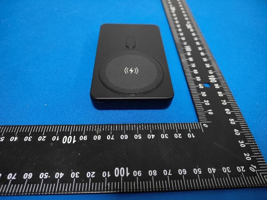
2A22V-QIS11
Jun 30, 20264-in-1 Wireless Charging Station-Power bank
Equipment Class
DCD - Part 15 Low Power Transmitter Below 1705 kHz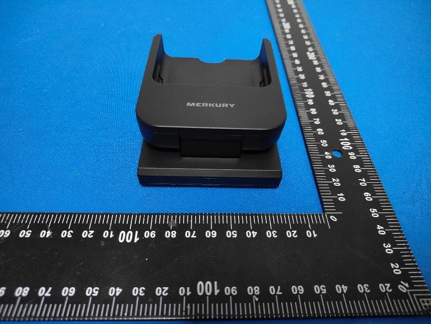
2A22V-QIS11B
Jun 29, 20264-in-1 Wireless Charging Station-Base
Equipment Class
DCD - Part 15 Low Power Transmitter Below 1705 kHz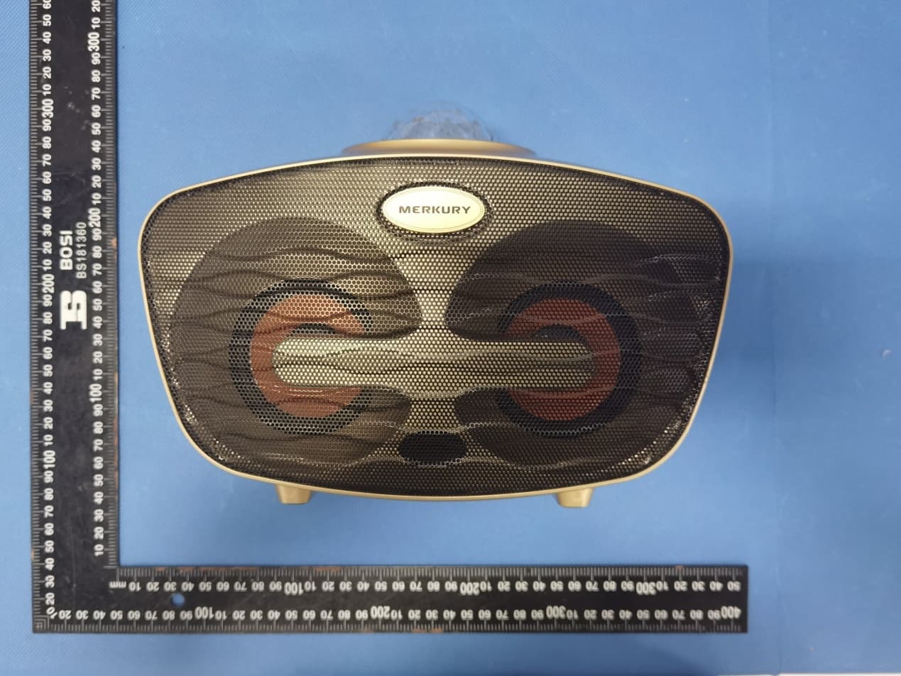
2A22V-MIS112B
Dec 08, 2022Duet Bluetooth Dual Karaoke Microphone
Equipment Class
DSS - Part 15 Spread Spectrum Transmitter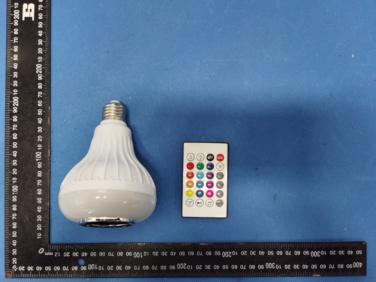
2A22V-MICS114
Nov 09, 2022LED bulb bluetooth speaker
Equipment Class
DTS - Digital Transmission System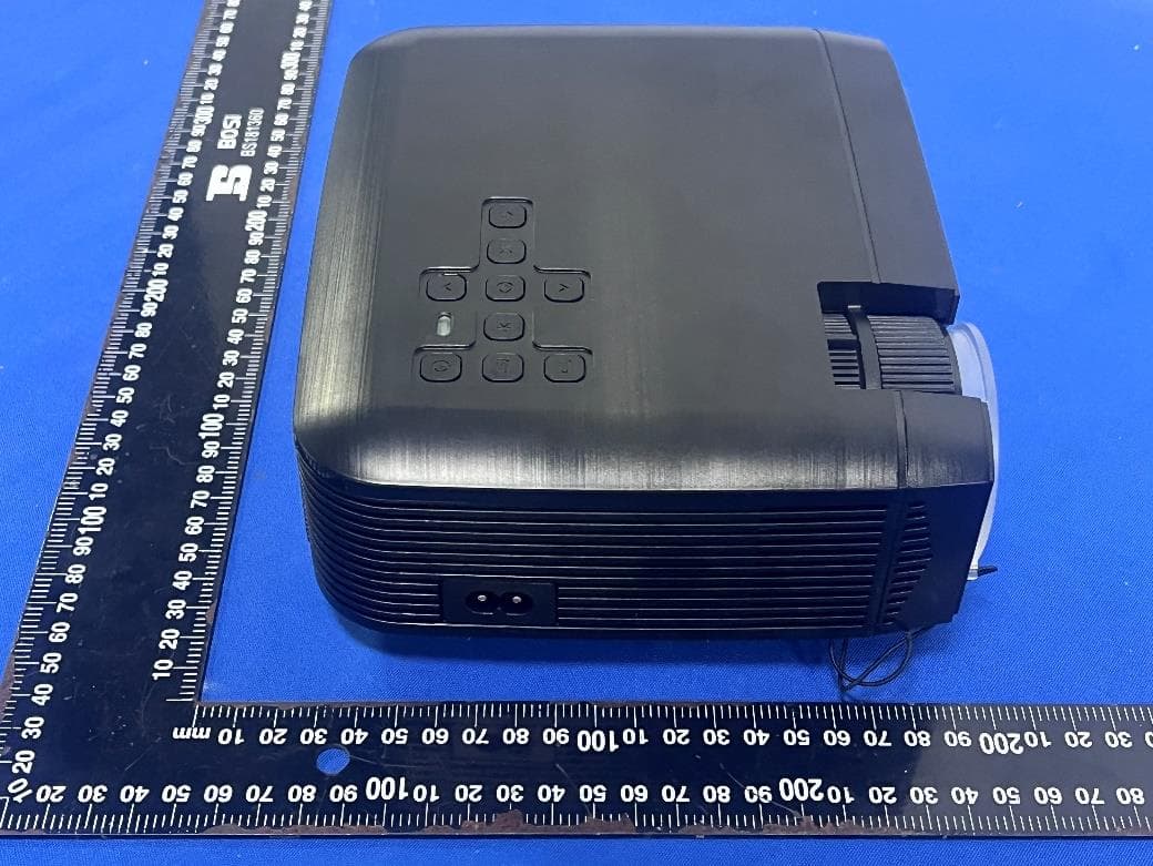
2A22V-MIP002B
Nov 09, 2022Wifi Projector
Equipment Class
DTS - Digital Transmission System