2A22V-MIP002BWifi Projector
Shenzhen DXR Electronic Technology Co., Limited (Dongguan Branch)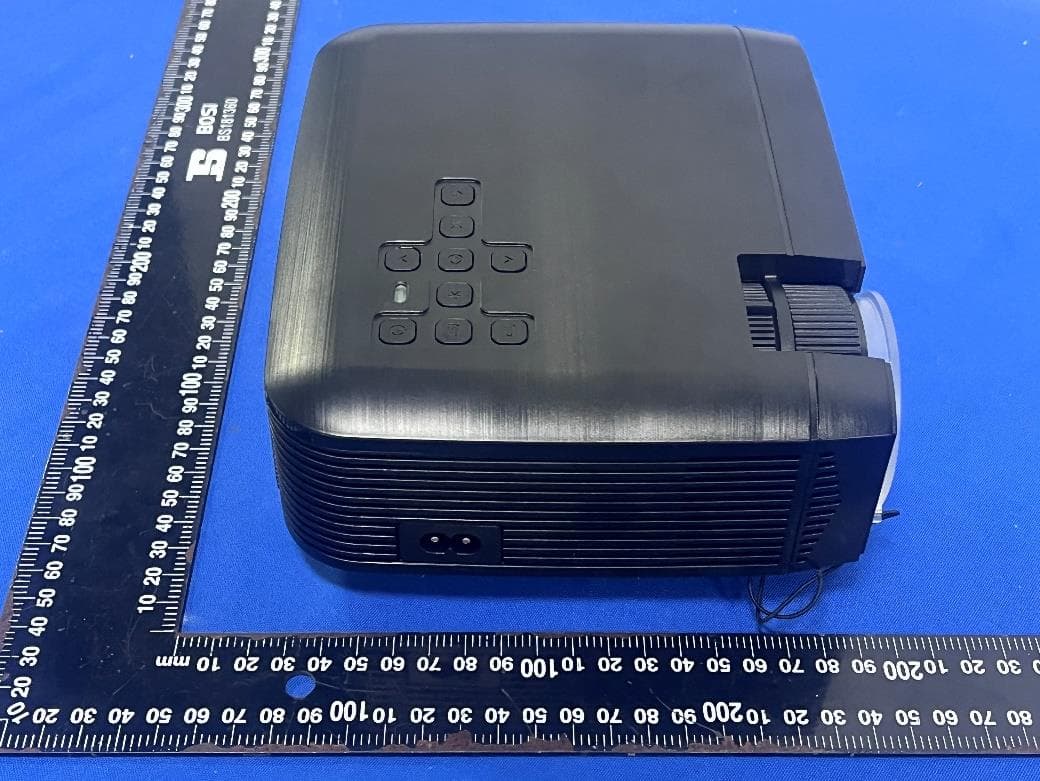
Click to zoom
Application Details
- Equipment Class
- DTS - Digital Transmission System
- Date of Grant
- Nov 09, 2022
- Application Purpose
- Original Equipment
- Date of Application
- Nov 09, 2022
- Equipment Note
- Wifi Projector
- Frequency Range
- 2412.00000000 - 2462.00000000
- Country
- China
Documents & Files
Document Text
Text extracted from the exhibit documents filed with the FCC. Open a document above to read the original.
Users Manual
SCREENCAST WIFI PROJECTOR+SCREEN IMPORTANTUser Manual for MI-P002B PLEASE READIncluded: BEFORE USINGProjector THIS PRODUCT100" Rpojection Screen Mounting Accessories Powerer cabl+HDMI cable+AV cable Remote control GETTING STARTED 1.Plug the power cord into the projector and connect the other end to a standard AC outlet - the projector's Power Indicator will be on red. 2. Press on the projector or remote control to start the projector. The Power Indicator light will stay blue once the device is powered on. A startup image will appear and the projector's fans will turn on. The device will not respond to commands HDMI while the device is warming up. 3. Plug your media source into the projector's correct input and power on the media source. ADJUST FOCUS, HEIGHT AND KEYSTONE 1. Rotate the Focus Ring to manually adjust focus. 2. Use the Height Adjuster to raise or lower the height of the projection. 3. Keystoning is when the projected image is noticeably wider at either the top or bottom. It occurs when the projector is not perpendicular to the screen.Correct the issue by adjusting the height of the projector and/or manually rotating the Keystone Ring. NAVIGATING THE MENU Select the correct connection in the projector's Menu based on the connected device DXR User Manual NAVIGATION ICONS FunctionIconDescription MediaVideo,music,picture from a connected USB drive or Micro SD card. HDMIFor Laptop,Game Console,etc. AVAudio/Visual, for DVD players and other playback devices VGAFor PC. DLANProjects what appears on media players. MiracastConnect your Android device using mirror via Wifi iOS CastConnect your iPhone using mirror via Wifi SettingProjector Settings Menu WiFi statusWiFi connected successfully CONNECTING DEVICES When connecting a hardwire source to the projector, be sure to: 1. For optimal use, restart your device before connecting to the projector 2. Use the correct cables for each input. 3. Make sure the cables are firmly inserted. You can connect your projector to any device using one of the following input ports HDMI VGA AV To use an external speaker with the projector, take a 3-in-1 AV cable and connect one end of the cable to the audio output port of the speaker and connect the other end to the projector's AV port. USB/MICRO SD MEDIA PLAY Insert USB Drive or Micro SD card and choose the Media icon, the projector can paly the following file types File typeFomat VideoMPEG-1,MPEG-2,MPEG-4, H.264,RM/RMVB,Sorenson Spark, FLV,MOV,MKV,MPG,WMV MusicMP1,MP2,MP3,MVA,Supports other audio formats PhotoJPEG/BMP/PNG CONNECTING TO WIFI SETTING UP WI-FI: 1.Select Wireless from the projector's settings menu and choose Wi-Fi. Search for available networks. 2. Choose the Wi-Fi network you'd like to connect to and enter the password when prompted via the on-screen keyboard and press enter. 3. If successful, you'll see the Wi-Fi name show on the top right of your screen. WIRELESSLY STREAM SMART DEVICE VIA MIRRORING (PROJECTOR MUST BE CONNECTED TO WI-FI) Smartphone Mirroring You can project what appears on your android or apple device through screen mirroring. You can do this wirelessly through wi-fi. iOS Wireless Mirror 1. On the projector, choose the iOS/Mac icon from the home screen. Be sure both the Apple device and the projector are connected to the same Wi-Fi 2. In your phone's settings, go to control center and tap Screen Mirroring. 3. Locate the projector on the device list and select it. Android Wireless Mirror 1. On the projector, choose the Android Mirror icon from the home screen. Be sure both the Android and the projector are connected to the same Wi-Fi 2. Choose the wireless display setting in your Android device. This could have many names depending on the brand of your Android phone. Ex: Miracast, Smart View,Multi-Screen etc You can also download the app'Miracast Shortcut' from the Google Play Store to connect faster. 3. Locate the projectof on the device list and select it. MOUNTING PROJECTION SCREEN 1. We recommend measuring where you anticipate placing the hooks first by laying the screer along the desired wall and marking the ends where the screen's loops will be. 2.Stick each hook onto an adhesive backing and place firmly on each marked corner and edge. 3.Attach the screen using the hooks! It's show time!. SETTINGS ADJUSTMENTS 1. Navigate to the icon from the control panel or remote control. The Menu will have the following options: Picture, Sound, Preference, Setup, and Network Setup (access this menu for the latest firmware updates available). 2. Use the right and left buttons on your remote control to move and alter settings in the Menu. Use the OK button to choose setting option. SPECIFICATIONS SPECIFICATIONS Contrast: 1000:1 Imaging Technology: LCD Resolution:1024x600 Power Supply: 110-240V50/60Hz Max Resolution: 600PPower Consumption: 55W Lamp: LED Input terminal: USB/Micro SD/ HDMI/VGA/AV Lamp Life:30,000 hours Lumens:1,600 Output Terminal: Earphone Output Adjust Focus: Manual Speaker Output: 2x 3W Keystone Correction:±15° OSD Language: 25 Size of projection: 36-150 inchesDistance of the projection(ft):3.3-13.1 Aspect Ratio: 16:10/16:9/4:3Dimensions(in): 7.99x6.77x3 PRODUCT LAYOUT 1Lens 2Height Adjuster 12 Power Supply: 100-240V50/60Hz Power Supply: 100-220V50/60Hz 563 43Focus Ring 4Keystone 5Up 6Right 7Left 8Return 9Home 10Menu 11OK 12Down 13Power 8 10 13 9 7 11 12 14Audio Output Jack 15AV Input 16Micro SD Card Slot 17HDMI Input 18USB Input 19VGA Input 14 1516 171819 Remote Control 1Power 2Menu 3Home 4Up 5Left 6Right 7OK 8Down 9Play/Pause 10Return 11Vol- 12Vol+ 13Mute FCC Compliance Statement: This device complies with Part 15 of the FCC Rules. Operation is subject to the following two conditions: (1) this device may not cause harmful interference, and (2) this device must accept any interference received, including interference that may cause undesired operation. Changes or modifications not expressly approved by the party responsible for compliance could void the user's auth…
Text truncated - open the document above for the full version.
External Photos
- Page 1 of 4 - ET-22102034 Product Name: Wifi Projector Model No.: MI-P002B - Page 2 of 4 - ET-22102034 - Page 3 of 4 - ET-22102034 - Page 4 of 4 - ET-22102034 ------END-----
ID Label/Location Info
Label and label location Label location
Internal Photos
- Page 1 of 6 - ET-22102034 Product Name: Wifi Projector Model No.: MI-P002B WIFI ANT - Page 2 of 6 - ET-22102034 - Page 3 of 6 - ET-22102034 - Page 4 of 6 - ET-22102034 - Page 5 of 6 - ET-22102034 - Page 6 of 6 - ET-22102034 ------END-----
RF Exposure Info
FCC ID: 2A22V-MIP002B RF Exposure Evaluation Limits The criteria listed in the following table shall be used to evaluate the environment impact of human exposure to radio frequency (RF) radiation as specified in 1.1307(b) Limits for Maximum Permissible Exposure (MPE) Frequency range (MHz) Electric field strength (V/m) Magnetic field strength (A/m) Power density (mW/cm 2 ) Averaging time (minutes) (A) Limits for Occupational/Controlled Exposures 0.3–3.0 614 1.63 *(100) 6 3.0–30 1842/f 4.89/f *(900/f 2 ) 6 30–300 61.4 0.163 1.0 6 300–1500 f/300 6 1500–100,000 5 6 (B) Limits for General Population/Uncontrolled Exposure 0.3–1.34 614 1.63 *(100) 30 1.34–30 824/f 2.19/f *(180/f 2 ) 30 30–300 27.5 0.073 0.2 30 300–1500 f/1500 30 1500–100,000 1.0 30 f = frequency in MHz Friis transmission formula: Pd = (Pout*G)/(4*pi*r 2 ) Where Pd = power density in mW/cm 2 , Pout = output power to antenna in mW; G = gain of antenna in linear scale, Pi = 3.1416; R = distance between observation point and center of the radiator in cm Pd id the limit of MPE, 1 mW/cm 2 . If we know the maximum gain of the antenna and the total power input to the antenna, through the calculation, we will know the distance r where the MPE limit is reached. Test Procedure Software provided by client enabled the EUT to transmit and receive data at lowest, middle and highest channel individually. FCC ID: 2A22V-MIP002B Test Result of RF Exposure Evaluation Antenna gain=1.24dBi For 2.4G WIFI Mode Output power (dBm) Output power (mW) Numeric antenna gain Power Density at R=20cm (mW/cm 2 ) Limit (mW/cm 2 ) Result 802.11b 14.25 26.61 1.33 0.0070 1.0 PASS 802.11g 17.77 59.84 1.33 0.0158 1.0 PASS 802.11n(HT20) 16.47 44.36 1.33 0.0117 1.0 PASS 802.11n(HT40) 15.06 32.06 1.33 0.0085 1.0 PASS Then SAR evaluation is not require . Remark: The source of the evaluation data results is based on the test report ET-22102034E
Test Report
Antenna specification Antenna type: Integrated antenna Frequency range: 2400-2500MHz 1. Antenna position 2. Match circuit-WIFI antenna 3. WIFI passive standing wave 4. Active power test data WIFI 2400-2500MHz CH 1 6 11 TRP 13.76 13.23 13.50 TIS -75.77 -80.02 -80.55 5. Passive 2.4G test results 6. 2.4G direction map
Test Report
Report No.: ET-22102034E Tel: +86 755 85259392 Email: [email protected] No.103, No.10, Phase I, Zone 3, Xinxing Industrial Park, Xinhe, Fuhai Street, Bao'an District, Shenzhen, Guangdong, China TEST REPORT Applicant: Shenzhen DXR Electronic Technology Co.,Limited(Dongguan Branch) Address of Applicant: 4th Floor, #5 Building, #189, Yongji Industrial, Zhuweitian, Fenggang Town, Dongguan, Guangdong, China Manufacturer/Factory: Shenzhen DXR Electronic Technology Co.,Limited(Dongguan Branch) Address of Manufacturer 4th Floor, #5 Building, #189, Yongji Industrial, Zhuweitian, Fenggang Town, Dongguan, Guangdong, China Product Name: Wifi Projector Model No.: MI-P002B Trade Mark: Merkury FCC ID: 2A22V-MIP002B Applicable standards: FCC CFR Title 47 Part 15 Subpart C Section 15.247 Date of Test: Oct.21, 2022- Oct.28, 2022 Date of report issued: Nov.07, 2022 Test Result : PASS * * In the configuration tested, the EUT complied with the standards specified above. Remark: The results shown in this test report refer only to the sample(s) tested , this test report cannot be reproduced, except in full without prior written permission of the company. The report would be invalid without specific stamp of test institute and the signatures of compiler and approver Prepared By Shenzhen ETR Standard Technology Co., Ltd. Address: No.103, No.10, Phase I, Zone 3, Xinxing Industrial Park, Xinhe, Fuhai Street, Bao'an District, Shenzhen, Guangdong, China Compiled by: Reviewed by: Approved by: Project Engineer Project Manager Authorized Signature - Page 2 of 52 - Report No.: ET-22102034E Report Revision History Report No. Description Issue Date ET-22102034E Original Nov.07, 2022 - Page 3 of 52 - Report No.: ET-22102034E Tel: +86 755 85259392 Email: [email protected] No.103, No.10, Phase I, Zone 3, Xinxing Industrial Park, Xinhe, Fuhai Street, Bao'an District, Shenzhen, Guangdong, China Contents Page 1. TEST SUMMARY ......................................................................................................................................4 2. GENERAL INFORMATION .......................................................................................................................5 2.1 GENERAL DESCRIPTION OF EUT .................................................................................................................5 2.2 TEST MODE ................................................................................................................................................7 2.3 DESCRIPTION OF SUPPORT UNITS ...............................................................................................................7 2.4 DEVIATION FROM STANDARDS .....................................................................................................................7 2.5 ABNORMALITIES FROM STANDARD CONDITIONS ...........................................................................................7 2.6 TEST FACILITY ............................................................................................................................................7 2.7 TEST LOCATION ..........................................................................................................................................7 2.8 ADDITIONAL INSTRUCTIONS .........................................................................................................................7 3. TEST INSTRUMENTS LIST ......................................................................................................................8 4. TEST RESULTS AND MEASUREMENT DATA .......................................................................................9 4.1 ANTENNA REQUIREMENT .............................................................................................................................9 4.2 CONDUCTED EMISSIONS ...........................................................................................................................10 4.3 CONDUCTED PEAK OUTPUT POWER ..........................................................................................................13 4.4CHANNEL BANDWIDTH ...............................................................................................................................15 4.5 POWER SPECTRAL DENSITY ......................................................................................................................19 4.6 BAND EDGES ............................................................................................................................................22 Conducted Emission Method ...................................................................................................................22 Radiated Emission Method ......................................................................................................................25 4.7 SPURIOUS EMISSION .................................................................................................................................30 Conducted Emission Method ...................................................................................................................30 Radiated Emission Method ......................................................................................................................35 5. TEST SETUP PHOTO .............................................................................................................................52 6. EUT CONSTRUCTIONAL DETAILS .......................................................................................................52 - Page 4 of 52 - Report No.: ET-22102034E Tel: +86 755 85259392 Email: [email protected] No.103, No.10, Phase I, Zone 3, Xinxing Industrial Park, Xinhe, Fuhai Street, Bao'an District, Shenzhen, Guangdong, China 1. Test Summary Test Item Section Result Test by Antenna requirement FCC part 15.203/15.247 (c) Pass / AC Power Line Conducted Emission FCC part 15.207 Pass Qiao Li Conducted Peak Output Power FC…
Text truncated - open the document above for the full version.
Test Setup Photos
ET-22102034 Page 1 of 2 Product Name: Wifi Projector Test Model No.: MI-P002B Test Setup Photo Radiated emissions 30MHz to1GHz Above 1GHz ET-22102034 Page 2 of 2 Conducted Emission ------End------
Contact Information
Applicant
Winnie He
Technical Contact
Test Firm
Shenzhen ETR Standard Technology Co., Ltd.Smith Chen
[email protected]+86 755-85259392
Technical Specifications
| # | Rule Parts | Frequency Range | Power Output |
|---|---|---|---|
| 1 | 15C | 2.41 GHz - 2.46 GHz | 59.80 mW |
Other Applications from Shenzhen DXR Electronic Technology Co., Limited (Dongguan Branch)
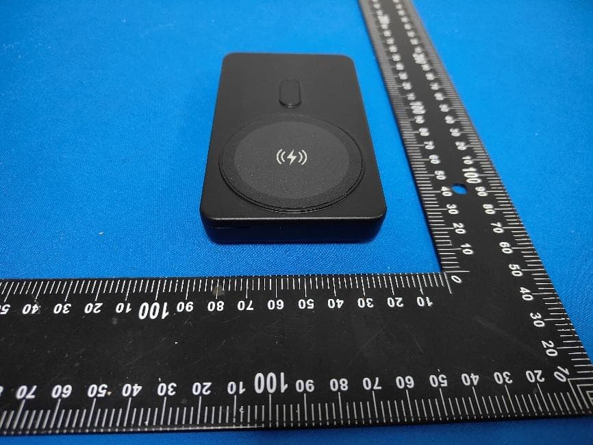
2A22V-QIS11
Jun 30, 20264-in-1 Wireless Charging Station-Power bank
Equipment Class
DCD - Part 15 Low Power Transmitter Below 1705 kHz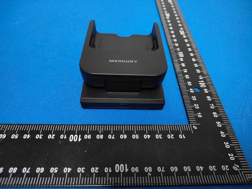
2A22V-QIS11B
Jun 29, 20264-in-1 Wireless Charging Station-Base
Equipment Class
DCD - Part 15 Low Power Transmitter Below 1705 kHz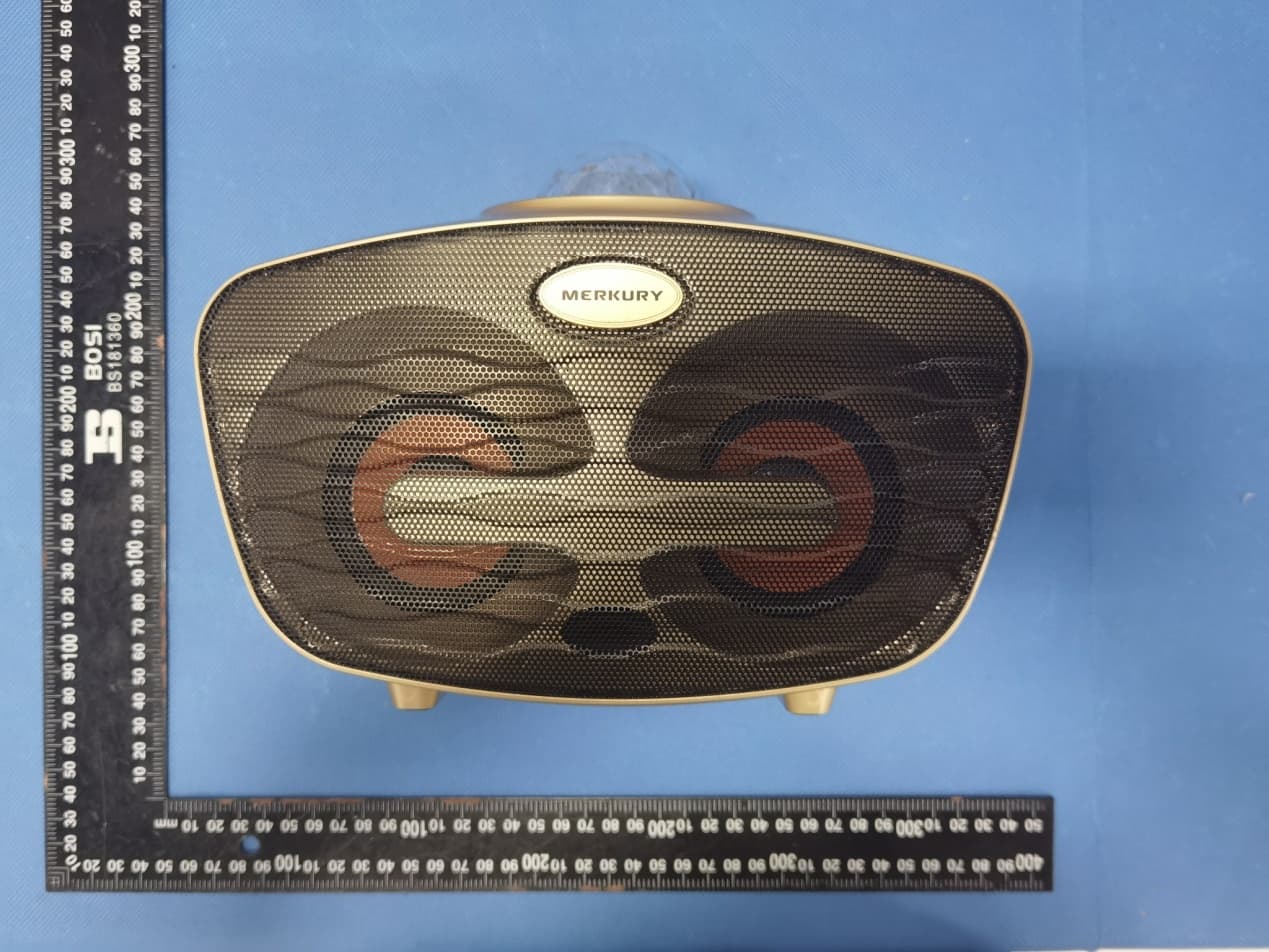
2A22V-MIS112B
Dec 08, 2022Duet Bluetooth Dual Karaoke Microphone
Equipment Class
DSS - Part 15 Spread Spectrum Transmitter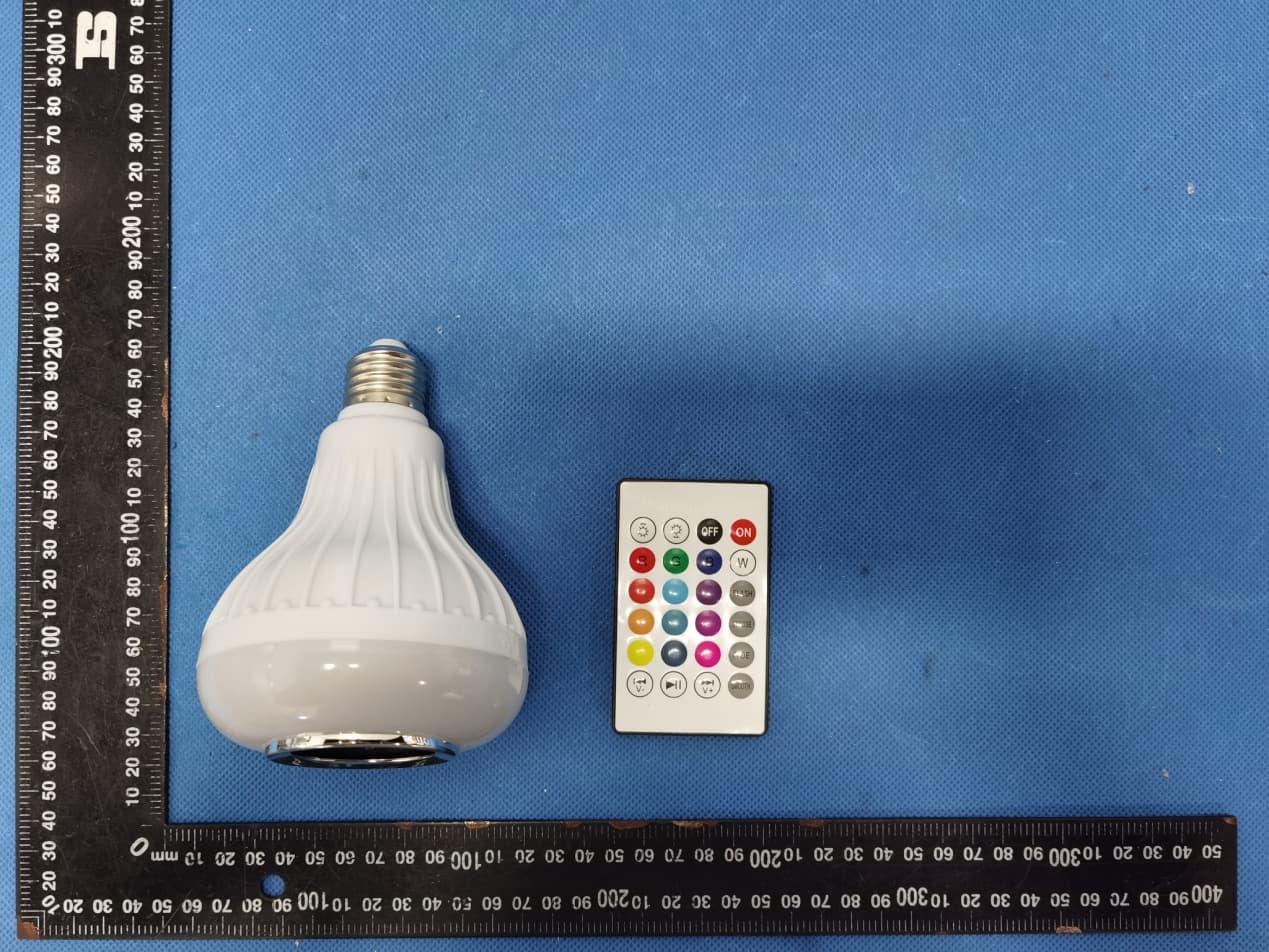
2A22V-MICS114
Nov 09, 2022LED bulb bluetooth speaker
Equipment Class
DTS - Digital Transmission System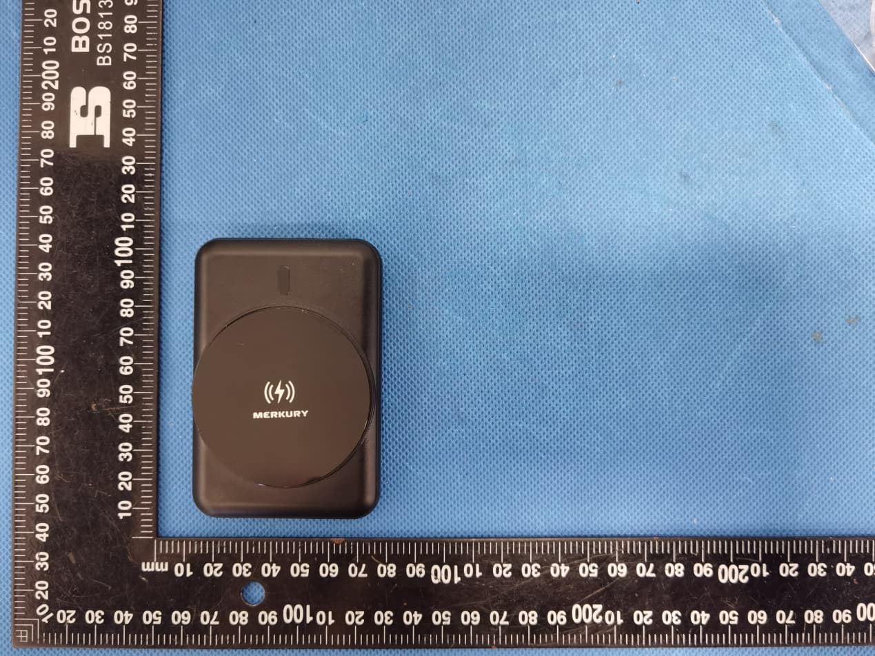
2A22V-MWP01
Jul 17, 2022Power Bank - Magnetic Wireless Charger
Equipment Class
8CC - Part 18 Consumer Device