2A3OOHD2DMR Digital Transceiver
Shenzhen Ysair Technology Co., LTD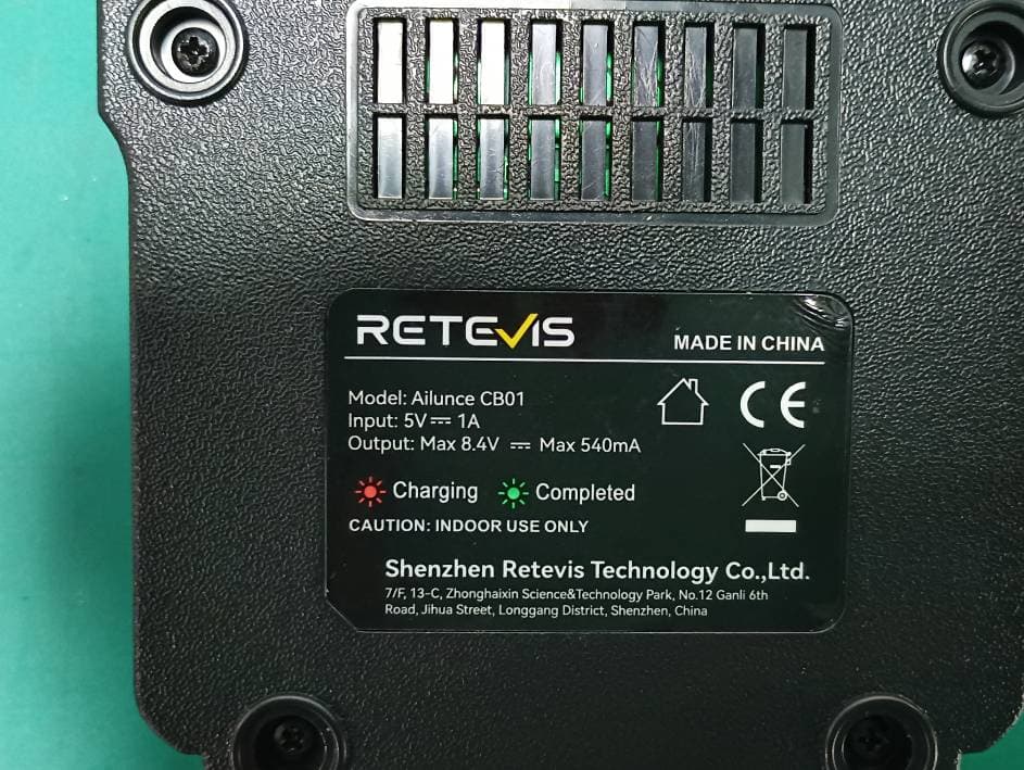
Click to zoom
Application Details
- Equipment Class
- DTS - Digital Transmission System
- Date of Grant
- May 20, 2024
- Application Purpose
- Original Equipment
- Date of Application
- May 20, 2024
- Equipment Note
- DMR Digital Transceiver
- Frequency Range
- 2402.00000000 - 2480.00000000
- Country
- China
Documents & Files
Document Text
Text extracted from the exhibit documents filed with the FCC. Open a document above to read the original.
Users Manual
1) Press the [MENU] key to turn off the radio, or turn on the radio, press [EXIT] to exit. 2)Long press the Exit button to switch between the VFO channel and MR storage channel in radio mode; 3)Long press the [* Scan] button to save the radio frequency as the radio channel; 4)Short press the [#] button to turn on or off DW. Dual Watch represents that in FM radio mode, if there is an intercom signal coming in, it will first switch to receiving the intercom signal. If the intercom signal disappears, it will return to the FM Radio signal. Version information Displays the Serial number and firmware version. Detailed functional operations 1 .Save an analog Channel 1)lnput 144.25000MHz on Band A or Band B; 2) Press the Menu key to enter Band A or Band B Set; 3)Set the C-CDC and/or the R-CDC. If the C-CDC or the R-CDC is different, then set C-CDC and R-CDC separately. 4)After completing the above operations, it is currently a temporary channel that can be used for transmission and reception. 5)Enter the Main Set- "Save CH" menu again, select an empty channel to save as a new channel. 2. Save a digital channel 1)lnput 144.25000MHz on Band A or Band B; 2)Long press the Exit button to switch between FM and DMR mode. 3)Select a Color Code; 4)DMR Mode: Simplex; 5)Choose DMR slot; 6)Select the Radio ID to be used for the current channel; 7)Select the call contact for the current channel. Return to the main interface to edit a temporary channel for communication; 8)Enter the Main Set- "Save CH" menu again, select an empty channel to save as new channel. 3 . Make an analog repeater channel 1)ln VFO mode, input a receiving frequency that is the same as the repeater transmission frequency; 2) For example, 439.2000MHz is the transmission frequency of the repeater, it will be the reception frequency of the radio; 3)Enter Band A or B to set the frequency difference direction, in the Shift Up menu item, choose "Minus", and Shift Freq edit 08.0000, The transmission frequency of the radio is 439.2000-8.0000 MHz, which is 431.20000 MHz; 4)The repeater generally has sub tone settings, Set the same CTCSS tone used by the repeater on the radio; 5)After completing the above operations, the standby interface of the radio will display 439.2000Mhz; 6)lt w display 431.20000Mhz and the CTCSS when transmitting. 4 .Make a digital repeater channel 1)ln VFO mode, input a receiving frequency that is the same as the repeater transmission frequency; 2) For example, 439.2000MHz is the transmission frequency of the repeater, it will be the reception frequency of the radio; 07 FM radio Ailunce HD2 is set to VHF144-146Mhz & UHF 430-440Mhz, this follows the IARU regions 1/2/3 frequency bands. Note:Selectable frequency bands differ, depending on the transceiver version. See the specification for details. (p.01) 32 FM Radio channels can be stored through computer program software; Channel scan 1)The priority channel can be set in the CPS as above picture shows. 2)When operating channel scan, if you choose a zone, it will scan all the channels in that zone, if you choose "ALL Channels" it will scan every channel you programmed for the radio. 6 .Emergency Alarm operation Choose remote alarm or local alarm in the CPS. the top orange key is default to emergency alarm key. Short press tostart emergency function, press again to stop alarm. 7.lmport 500,000 DMR contacts operation The HD2 hasthe ability to upload 500,000 DMR contacts into theradio.Downloadthe digital contacts from Ailunce websitehttps://www.ailunce.com/ResourceCenter/ Digital Contacts U.S.State Abbreviate: s DOWNLOAD 08 3)Enter Band A or B to set the frequency difference direction, in the Shift Up menu item,choose "Minus", and Shift Freq edit 08.0000,The transmission frequency of the radio is 439.2000- 8.0000 MHz, which is 431.20000 MHz; 4)Choose a same color code with the repeater color code on the radio Band A or B set. 5)Choose DMR mode "repeater" for a repeater channel. 6)Choose a communication contact for this repeater channel; 7) After completing the above operations, go back to the standby interface. It will display the frequency 439.2000Mhz, and DMR icon. 5 .Frequency Scan and channel Scan operation Frequency Scan 1)ln the CPS, you can set the start and end scan frequency for VHF and UHF. 2)UnderVFO mode, Short press [*SCAN] button to begin frequency scan, shortly press [*SCAN] w stop the frequency scan
Users Manual
Any Changes or modifications not expressly approved by the party responsible for compliance could void the user's authority to operate the equipment. This device complies with part 15 of the FCC Rules. Operation is subject to the following two conditions: (1) This device may not cause harmful interference, and (2) this device must accept any interference received, including interference that may cause undesired operation. This device complies with Innovation, Science, and Economic Development Canad licence-exempt RSS standard(s). Operation is subject to the following two conditions: (1) this device may not cause interference, and (2) this device must accept any interference, including interference that may cause undesired operation of the device. Le présent appareil est conforme aux CNR d' Innovation, Sciences et Développement économique Canada applicables aux appareils radio exempts de licence. L'exploitation est autorisée aux deux conditions suivantes : (1) l'appareil nedoit pas produire de brouillage, et (2) l'utilisateur de l'appareil doit accepter tout brouillage radioélectrique subi, même si le brouillage est susceptible d'en compromettre le fonctionnement. This radio is intended for use in occupational/controlled applications where users have been made aware of the potential risks for exposure and can exercise control over their exposure. This product is not authorised for general population, consumer or similar use. This transmitter must not be co-located or operated in conjunction with any other antenna or transmitter. Your radio should be used in its normal operating position when hand-held, worn on the body or secured within a cradle. Always ensure that the antenna is pointed away from the body, particularly the eyes. When body-worn, the radio must be secured using a approved attachment. Ensure the antenna is at least 2.5 cm (1 in.) away from the body when transmitting. Cette radio est adaptée aux applications professionnelles / contrôlées où l'utilisateur est conscient des risques potentiels d'exposition et peut contrôler son exposition. Ce produit n'est pas autorisé pour la population générale, les consommateurs ou des utilisations similaires. Cet émetteur ne doit pas coexister ou fonctionner conjointement avec toute autre antenne ou émetteur. Lorsque votre radio est tenue à la main, portée sur votre corps ou fixée dans un support, elle doit être utilisée dans sa position de travail normale. Assurez - vous toujours que l'antenne pointe dans une direction éloignée du corps, en particulier des yeux. Lorsque la carrosserie est usée, la radio doit être fixée avec un accessoire approuvé. Lors de l'émission, assurez - vous que l'antenne se trouve à au moins 2,5 cm (1 po) du fuselage. ATTENTION! When programming the radio, start by reading the factory software data, and then rewrite this data with your frequency etc., to a new saved code plug, otherwise errors may occur. You can use the programming cabl e with a PC to program the authorized frequency, bandwidth, power, etc. your programming must comply with your FCC license certification. The radio receiver has the ability to scan a wide range of radio frequencies (136-174/400-520 MHZ)and lock on to any transmission that it receives.
Attestation Statements
She Add Roa Ema Tel: Dat FE D Aut 743 Colu De a Th e Tra this fun c end Sin c Sign Don Titl nzhen Ysair dress: Room ad, Yangmei ail: retevis@ +86-755-23 e: 2024-04- DERAL CO thorization a 5 Oakland M umbia, MD ar Sir or Ma e Bluetooth ansceiver, m module on ctions, band user has no cerely, nature: ngfang Shen e:Manager r Technolog m 403, 4th F Communit @126.com 3481953 -19 OMMUNICA and Evaluat Mills Road D 21046 adam, module, mo model:HD2, nly supports ds and mode o capability n y Co., LTD loor, Buildi n ty Bantian S ATIONS C tion Divisio Atte odel: BTA5 , HD3,H1,H BT(GFSK es was disab to activate ng 4, Yunli I treet, Longg COMMISSIO on estation le 512 installed H2, FCC ID K, π/4-DQPS bled to use b it. ntelligent P gang Distric ONS etter d in our prod : 2A3OOH SK, 8DPSK by manufac Park, No. 3 C ct, Shenzhe duct DMR HD2, for ma K), BLE 1M cturer in the Changfa Mi n china Di gital arketing purp M.The other e software, t ddle pose, r the
Attestation Statements
Shenzhen Ysair Technology Co., LTD Address: Room 403, 4th Floor, Building 4, Yunli Intelligent Park, No. 3 Changfa Middle Road, Yangmei Community Bantian Street, Longgang District, Shenzhen China Email: [email protected] Tel: +86-755-23481953 CFR 47 §2.911(d)(5)(i) Attestation Letter Attestation Letter Date: 19/04/2024 FEDERAL COMMUNICATIONS COMMISSIONS Authorization and Evaluation Division 7435 Oakland Mills Road Columbia, MD 21046 Ref: Attestation Statements CFR 47 §2.911(d)(5)(i) Filing FCC ID:2A3OOHD2 Shenzhen Ysair Technology Co., LTD certifies that the equipment for which authorization is sought, is not “covered” equipment prohibited from receiving an equipment authorization pursuant to section 2.903 of the FCC rules. Sincerely, Signature: Dongfang Shen Title:Manager
Attestation Statements
Shenzhen Ysair Technology Co., LTD Address: Room 403, 4th Floor, Building 4, Yunli Intelligent Park, No. 3 Changfa Middle Road, Yangmei Community Bantian Street, Longgang District, Shenzhen China Email: [email protected] Tel: +86-755-23481953 CFR 47 §2.911 (d)(5)(ii) Attestation Letter Attestation Letter Date: 19/04/2024 FEDERAL COMMUNICATIONS COMMISSIONS Authorization and Evaluation Division 7435 Oakland Mills Road Columbia, MD 21046 Ref: Attestation Statements CFR 47 §2.911(d)(5)(ii) Filing FCC ID:2A3OOHD2 Shenzhen Ysair Technology Co., LTD certifies that as of the date of the filing of the application, the applicant is not identified on the Covered List as an entity producing “covered” equipment. Sincerely, Signature: Dongfang Shen Title:Manager
Attestation Statements
U.S. AGENT LETTER OF ATTESTATION Date: 2024-04-19 FEDERAL COMMUNICATIONS COMMISSION Authorization and Evaluation Division 7435 Oakland Mills Road Columbia, MD 21046 Ref: Attestation Statements CFR 47 §2.911(d)(7) Filing FCC ID:2A3OOHD2 Shenzhen Ysair Technology Co., LTD certifies that, as of the date of the filing of the application, RETEVIS INC is our designated U.S. agent for service of process for the above referenced FCC ID. Shenzhen Ysair Technology Co., LTD accepts to maintain an agent for no less than one year after the grantee has terminated all marketing and importation or the conclusion of any Commission-related proceeding involving the equipment. RETEVIS INC accepts, as of the date of the filing of the application, the obligation of the designated U.S. agent for service of process for the above referenced FCC ID. Designated U.S. Agent Information: Name: RETEVIS INC Address: 1733 E BROOKPORT ST, COVINA, CA 91724 FRN: 0033657701 Tel.: +1 (626) 3622594 Email: [email protected] Signed by (printed name): Liuye Li Signature: Applicant: Shenzhen Ysair Technology Co., LTD Address: Room 403, 4th Floor, Building 4, Yunli Intelligent Park, No. 3 Changfa Middle Road, Yangmei Community Bantian Street, Longgang District, Shenzhen China FRN:0031641426 Tel: +86-755-23481953 Email: [email protected] Signed by (printed name): Dongfang Shen Signature:
Cover Letter(s)
Shenzhen Ysair Technology Co., LTD Address: Room 40 3, 4th Floor, Building 4, Yunli Intelligent Park, No. 3 Changfa Middle Road, Yan gmei Community Bantian Street, Longgang District, Shenzhen China Email: [email protected] Tel: +86-755-23481953 QA-FR-170-B 7/29/2014 FCC Authorization Date: 2024-04-19 FEDERAL COMMUNICATIONS COMMISSIONS Authorization and Evaluation Division 7435 Oakland Mills Road Columbia, MD 21046 Subject: Agent Authorization To whom it may concern: We, Shenzhen Ysair Technology Co., LTD, the undersigned, hereby authorizes Bay Area Compliance Laboratories Corp. (Shenzhen) to act on its behalf in all matters relating to application for Equipment authorization, including the signing of all documents relating to these matters. All acts carried out by Bay Area Compliance Laboratories Corp. (Shenzhen) on our behalf shall have the same effect as our own action. We, the undersigned, hereby certify that we are not subject to a denial of federal benefits, that includes FCC benefits, pursuant to Section 5301 of the Anti-Drug Abuse Act of 1988, 21 U.S.C. 862. This authorization is valid until further written notice from the applicant. Sincerely, Signature: D ongfang Shen Title:Manager
Cover Letter(s)
Shenzhen Ysair Technology Co., LTD Address: Room 403, 4th Floor, Building 4, Yunli Intelligent Park, No. 3 Changfa Middle Road, Yangmei Community Bantian Street, Longgang District, Shenzhen china Email: [email protected] Tel: +86-755-23481953 FCC Confidential Authorization Date: 2024-04-19 FEDERAL COMMUNICATIONS COMMISSIONS Authorization and Evaluation Division 7435 Oakland Mills Road Columbia, MD 21046 Subject: Confidentiality Request regarding application for certification of FCC ID:2A3OOHD2 In accordance with Sections 0.457 and 0.459 of the Commission’s Rules, Shenzhen Ysair Technology Co., LTD hereby requests long-term confidential treatment of information accompanying this application as outlined below: • Block Diagram • Schematics • Operation Description • Internal Photos The above materials contain proprietary and confidential information not customarily released to the public. The public disclosure of these materials provides unjustified benefits to its competitors in the market. Sincerely, Signature: Dongfang Shen Title:Manager
Cover Letter(s)
Shenzhen Ysair Technology Co., LTD Address: Room 403, 4th Floor, Building 4, Yunli Intelligent Park, No. 3 Changfa Middle Road, Yangmei Community Bantian Street, Longgang District, Shenzhen china Email: [email protected] Tel: +86‐755‐23481953 Product Similarity Declaration Date: 2024-04-12 To: FEDERAL COMMUNICATIONS COMMISSIONS Authorization and Evaluation Division 7435 Oakland Mills Road Columbia, MD 21046 Dear Sir/Madam, We, Shenzhen Ysair Technology Co., LTD hereby declare that we have a product named as DMR Digital Transceiver (model: HD2, HD3,H1,H2, FCC ID:2A3OOHD2), all the models are identical in electrically, The difference is only that HD2, HD3 have GPS module ; H1,H2 have not GPS module. We confirm that all information above is true, and we’ll be responsible for all the consequences. Please contact me if you have any question. Sincerely, Signature: Dongfang Shen Title:Manager
External Photos
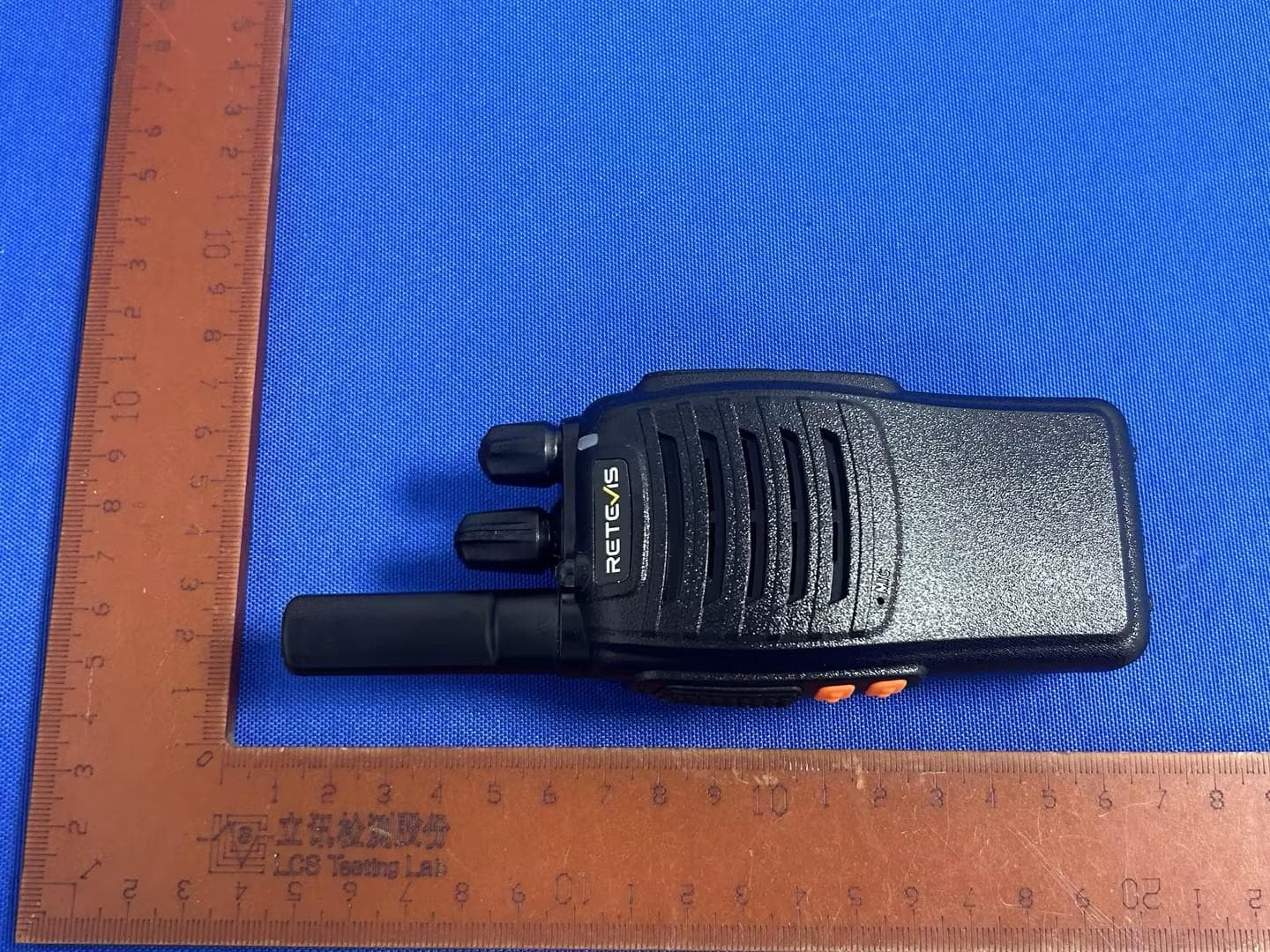
Bay Area Compliance Laboratories Corp. (Shenzhen) Project No.: SZ4240130-07027E-RF Page 1 of 12 EXHIBIT B - EUT EXTERNAL PHOTOGRAPHS Model: HD2, HD3 PTT ANT Bay Area Compliance Laboratories Corp. (Shenzhen) Project No.: SZ4240130-07027E-RF Page 2 of 12 Bay Area Compliance Laboratories Corp. (Shenzhen) Project No.: SZ4240130-07027E-RF Page 3 of 12 Bay Area Compliance Laboratories Corp. (Shenzhen) Project No.: SZ4240130-07027E-RF Page 4 of 12 Bay Area Compliance Laboratories Corp. (Shenzhen) Project No.: SZ4240130-07027E-RF Page 5 of 12 Model: H1, H2 PTT ANT Bay Area Compliance Laboratories Corp. (Shenzhen) Project No.: SZ4240130-07027E-RF Page 6 of 12 Bay Area Compliance Laboratories Corp. (Shenzhen) Project No.: SZ4240130-07027E-RF Page 7 of 12 Bay Area Compliance Laboratories Corp. (Shenzhen) Project No.: SZ4240130-07027E-RF Page 8 of 12 Charger Bay Area Compliance Laboratories Corp. (Shenzhen) Project No.: SZ4240130-07027E-RF Page 9 of 12 Bay Area Compliance Laboratories Corp. (Shenzhen) Project No.: SZ4240130-07027E-RF Page 10 of 12 Bay Area Compliance Laboratories Corp. (Shenzhen) Project No.: SZ4240130-07027E-RF Page 11 of 12 Bay Area Compliance Laboratories Corp. (Shenzhen) Project No.: SZ4240130-07027E-RF Page 12 of 12
ID Label/Location Info
Bay Area Compliance Laboratories Corp. (Shenzhen) Project No.: SZ4240130-07027E-RF EXHIBIT A - FCC ID LABEL AND LOCATION Label 1 Label 2 FCC ID Label Location Information The label shown shall be permanently affixed at a conspicuous location on the device and be readily visible to the user at the time purchase (Labeling requirements per 2.925) Label 1 Label 2
RF Exposure Info
Bay Area Compliance Laboratories Corp. (Shenzhen) Report No.: SZ4240130-07027E-RF-00A TR-EM-RF003 Page 11 of 47 Version 1.0 (2023/10/07) FCC§15.247 (i), §1.1307 (b) (1) & §2.1093 - RF EXPOSURE Applicable Standard According to FCC §2.1093 and §1.1307(b) (1), systems operating under the provisions of this section shall be operated in a manner that ensure that the public is not exposed to radio frequency energy level in excess of the Commission’s guideline. According to KDB 447498 D01 General RF Exposure Guidance The 1-g and 10-g SAR test exclusion thresholds for 100 MHz to 6 GHz at test separation distances ≤ 50 mm are determined by: [(max. power of channel, including tune-up tolerance, mW)/(min. test separation distance, mm)] · [√f(GHz)] ≤ 3.0 for 1-g SAR and ≤ 7.5 for 10-g extremity SAR, where 1. f(GHz) is the RF channel transmit frequency in GHz. 2. Power and distance are rounded to the nearest mW and mm before calculation. 3. The result is rounded to one decimal place for comparison. 4. When the minimum test separation distance is < 5 mm, a distance of 5 mm is applied to determine SAR test Exclusion. Measurement Result For worst case: Mode Frequency (MHz) Max tune-up conducted power # (dBm) Max tune-up conducted power # (mW) Distance (mm) Calculated value Threshold (1-g SAR) SAR Test Exclusion BLE 2402-2480 2.5 1.78 5 0.6 3.0 Yes Result: Compliant
Test Report
Note: The information marked # is provided by the applicant, the laboratory is not responsible for its authenticity and this information can affect the validity of the result in the test report. Customer model name, addresses, names, trademarks etc. are included. This report cannot be reproduced except in full, without prior written approval of the Company. Unless otherwise stated the results shown in this test report refer only to the sample(s) tested. This report is valid only with a valid digital signature. The digital signature may be available only under the Adobe software above version 7.0. This report must not be used by the customer to claim product certification, approval, or endorsement by NVLAP or any agency of the U.S. Government. This report may contain data that are not covered by the NVLAP accreditation and are marked with an asterisk “▼”. Bay Area Compliance Laboratories Corp. (Shenzhen) 5F(B-West) , 6F, 7F, the 3rd Phase of Wan Li Industrial Building D, Shihua Rd, FuTian Free Trade Zone, Shenzhen, China Tel: +86-755-33320018 Fax: +86-755-33320008 www.baclcorp.com.cn TR-EM-RF003 Page 1 of 47 Version 1.0 (2023/10/07) TEST REPORT Applicant Name: Shenzhen Ysair Technology Co., LTD Address: Room 403, 4th Floor, Building 4, Yunli Intelligent Park, No. 3 Changfa Middle Road, Yangmei Community Bantian Street, Longgang District, Shenzhen China Report Number: SZ4240130-07027E-RF-00A FCC ID: 2A3OOHD2 Test Standard (s) FCC PART 15.247 Sample Description Product Type: DMR Digital Transceiver Model No.: HD2 Multiple Model(s) No.: HD3,H1,H2 Trade Mark: RETEVIS Date Received: 2024/01/30 Issue Date: 2024/04/30 Test Result: Pass ▲ ▲ In the configuration tested, the EUT complied with the standards above. Prepared and Checked By: Approved By: Brace Lin Nancy Wang RF Engineer RF Supervisor Bay Area Compliance Laboratories Corp. (Shenzhen) Report No.: SZ4240130-07027E-RF-00A TR-EM-RF003 Page 2 of 47 Version 1.0 (2023/10/07) TABLE OF CONTENTS DOCUMENT REVISION HISTORY ......................................................................................................................... 4 GENERAL INFORMATION ....................................................................................................................................... 5 PRODUCT DESCRIPTION FOR EQUIPMENT UNDER TEST (EUT) ..................................................................................... 5 OBJECTIVE ................................................................................................................................................................... 5 TEST METHODOLOGY .................................................................................................................................................. 5 MEASUREMENT UNCERTAINTY .................................................................................................................................... 6 TEST FACILITY ............................................................................................................................................................. 6 SYSTEM TEST CONFIGURATION .......................................................................................................................... 7 DESCRIPTION OF TEST CONFIGURATION ...................................................................................................................... 7 EQUIPMENT MODIFICATIONS ....................................................................................................................................... 7 EUT EXERCISE SOFTWARE .......................................................................................................................................... 7 DUTY CYCLE ................................................................................................................................................................ 7 EXTERNAL I/O CABLE .................................................................................................................................................. 8 BLOCK DIAGRAM OF TEST SETUP ................................................................................................................................ 8 SUMMARY OF TEST RESULTS ............................................................................................................................... 9 TEST EQUIPMENT LIST ......................................................................................................................................... 10 FCC§15.247 (I), §1.1307 (B) (1) & §2.1093 - RF EXPOSURE ..................................................................................... 11 APPLICABLE STANDARD ............................................................................................................................................ 11 FCC §15.203 – ANTENNA REQUIREMENT .......................................................................................................... 12 APPLICABLE STANDARD ............................................................................................................................................ 12 ANTENNA CONNECTOR CONSTRUCTION .................................................................................................................... 12 FCC §15.209, §15.205 & §15.247(D) – UNWANTED EMISSION FREQUENCIES AND RESTRICTED BANDS13 APPLICABLE STANDARD ............................................................................................................................................ 13 EUT SETUP ................................................................................................................................................................ 13 EMI TEST RECEIVER & SPECTRUM ANALYZER SETUP .............................................................................................. 14 TEST PROCEDURE ............................................................................................................…
Text truncated - open the document above for the full version.
Test Report
根 通 通 信 技 术 有 限 公 司 Gentong Communication Technology Co.,Ltd 地址: 泉州市南安国家大学科学园福建分园七号楼五层 Add: 5th Floor, Building 7, Fujian Branch Park, Nanan National University Science Park, Quanzhou City, Gentong Communication Technology Co.,Ltd BT Skyline acceptance letter Name :BTA512 根 通 通 信 技 术 有 限 公 司 Gentong Communication Technology Co.,Ltd 泉州市南安国家大学科学园福建分园七号楼五层,电话:15889795946 1. Passive test fixture Objective: To test the passive parameters of antenna as accurately as possible. Production method: The hand mechanism is a 50 ohm coaxial cable, one end of which is connected to the test point at the back end of the matching circuit (front end of the RF test hole) of the mobile phone motherboard, and the other end is connected to the SMA connector. 2. S11 test S11 Test Method Description: Test equipment: Network analyzer (Agilent 8753D) Test method: A 50 ohm CABLE is exported from the instrument test port, and the SMA connector of the hand mechanism is connected after calibration with the calibration component. The return loss and standing wave ratio corresponding to the relevant frequency points are recorded. 3 Argument frequency(MHZ) 2400 2450 2500 Return loss (dB) -8.57 -22.66 -9.83 Standing-wave ratio 1.3 1.26 1.29 根 通 通 信 技 术 有 限 公 司 Gentong Communication Technology Co.,Ltd 泉州市南安国家大学科学园福建分园七号楼五层,电话:15889795946 4 Antenna Test Report Freq Effi Effi Gain (MHz) (%%) (dB) (dBi) 2400 38.83 -0.41 -0.57 2420 40.12 -0.39 -0.03 2440 40.33 -0.39 -0.05 2460 39.39 -0.40 -0.05 2480 38.52 -0.41 0.0 2500 36.55 -0.43 -0.17 根 通 通 信 技 术 有 限 公 司 Gentong Communication Technology Co.,Ltd 泉州市南安国家大学科学园福建分园七号楼五层,电话:15889795946 5 Size 9.5*4.3MM
Test Setup Photos
Bay Area Compliance Laboratories Corp. (Shenzhen) Report No.: SZ4240130-07027E-RFA Page 1 of 3 EXHIBIT D - TEST SETUP PHOTOGRAPHS For Model: H1 Radiated Emissions View (Below 30MHz) Radiated Emissions View (Below 1 GHz) Bay Area Compliance Laboratories Corp. (Shenzhen) Report No.: SZ4240130-07027E-RFA Page 2 of 3 For Model: HD2 Radiated Emissions View (Below 30MHz) Radiated Emissions View (Below 1 GHz) Bay Area Compliance Laboratories Corp. (Shenzhen) Report No.: SZ4240130-07027E-RFA Page 3 of 3 Radiated Emissions View (Above 1 GHz)
Contact Information
Applicant
Dongfang Shen(Manager)
Test Firm
Bay Area Compliance Laboratories Corp (Shenzhen)Well Wang
[email protected]86-755-33320018
Technical Specifications
| # | Rule Parts | Frequency Range | Power Output |
|---|---|---|---|
| 1 | 15C | 2.40 GHz - 2.48 GHz | 1.70 mW |
Other Applications from Shenzhen Ysair Technology Co., LTD
2A3OOH777H
Oct 11, 2024Two Way Radio
Equipment Class
FRF - Part 95 Family Radio Face Held Transmitter
2A3OORB48P
Aug 18, 2024Two Way Radio
Equipment Class
TNF - Licensed Non-Broadcast Transmitter Held to Face
2A3OOHS4
Aug 11, 2024Mobile Radio
Equipment Class
CSR - Scanning Receiver
2A3OORTA1
May 01, 2024Amateur Radio
Equipment Class
CSR - Scanning Receiver2A3OO-P2
Apr 10, 2024Two Way Radio
Equipment Class
TNF - Licensed Non-Broadcast Transmitter Held to Face