2A3OOHS4Mobile Radio
Shenzhen Ysair Technology Co., LTD
Click to zoom
Application Details
- Equipment Class
- CSR - Scanning Receiver
- Date of Grant
- Aug 11, 2024
- Application Purpose
- Original Equipment
- Date of Application
- Aug 11, 2024
- Equipment Note
- Mobile Radio
- Frequency Range
- 28.00000000 - 29.70000000
- Country
- China
Documents & Files
Document Text
Text extracted from the exhibit documents filed with the FCC. Open a document above to read the original.
Users Manual
Ailunce HS4 User Manual Contents FUNCTIONS & FEATURES WARNING INSTALLATION HOW TO USE YOUR RADIO FUNCTION MENU SETUP RESET FUNCTION (Resume Factory Default) SPECIFICATIONS CAUTION Guarantee ------------------------------------------------------------------------------01 ---------------------------------------------------------------------------------------------01 -----------------------------------------------------------------------------------------01 ------------------------------------------------------------------------------03 --------------------------------------------------------------------------------07 --------------------------------------------------------------08 ----------------------------------------------------------------------------------------09 ----------------------------------------------------------------------------------------------10 ----------------------------------------------------------------------------------------------12 01 FUNCTIONS & FEATURES 1. Large LCD panel which displays frequency and all kinds of information 2. DUAL-DIGITAL TUBE FOR CHANNEL DISPLAY 3. USE EL technology for backlight 4. PA、CW、AM、FM、USB、LSB mode 5. A、B、C、D、E、F , 6 banks in total, where 60 channels at least can be individually programmed. 6. Frequency Tuning Step can be 10HZ, 100HZ, 1KHZ or 10KHZ. 7. Multiple CLARIFIER Operating Modes 8. Flexible menu functions and PC programming software to meet varied customer demands 9. ECHO Function 10.SQ, ASQ Function (FM and AM mode only) 11.RF GAIN ADJUSTMENT 12.RF Power ADJUSTMENT 13.SCAN FUNCTION 14.RB FUNCTION 15.NB/ANL FUNCTION 16.DW DUAL-WATCH FUNCTION 17.BEEP VOICE PROMPT 18.+10KHZ Function 19.SWR、S/RF、DC Voltage display function 20.TOT function 21. HI-CUT FUNCTION 22.EMG CALL 23.SWR PROTECTION 24.POWER SUPPLIED VOLTAGE PROTECTION 25.Key-Lock Function 26.VOX function 27.CTCSS/DCS code 28.RX compander: noise blanker 29.Noise gate setting: mic noise adjustable 30.RX Noise Reduction 31.Compatible with “electronic” and “dynamic” MIC type WARNING To use the radio, please connect the antenna to the jack "B" on the back panel of the equipment first and then measure the SWR (Standing Wave Ratio) before transmitting (at this subject read the chapter nr.5/ page 3). A badly tuned antenna can destroy the final TX amplifier, these components are NOT covered under warranty. INSTALLATION 1. WHERE AND HOW TO MOUNT YOUR RADIO a) It is important to identify the proper place of the installation by considering "key criteria", such as easy access and congenial spaces with freedom of movement. b) The radio must not compromise the comfort of either: the driver and the passengers. c) Remember to provide cables in harmony with safety and prevention "standards". As well as guide their wiring in protected channels (eg: power supply, antenna, accessory wiring), so that they do not interfere in any way with the driving of vehicles. d) To install your equipment, use the bracket (1) and the self-tapping screws [2] provided (drilling diameter 5 mm). Be careful not to damage the vehicle's electrical system when drilling the dashboard. e) Do not forget to insert the rubber joints [3] between the radio and its bracket as they have a cushioning effect that allows a delicate orientation and tightening of the device. f) Choose where to place the microphone holder and remember that the microphone cable must extend to the driver without interfering with the vehicle's controls. 2. ANTENNA INSTALLATION 02 a) Antenna selection: For the best signal radiation, a well-calibrated antenna length is very important, on the other hand, there are other factors to be considered: the size of the vehicle and its usual speed. b) Mobile antenna: -Must be fixed to the vehicle where there is a maximum of metallic surface (ground plane) away from windscreen mountings. -There are two types of antennas: Pre-Regulated Antenna which should be used on a good ground plane (e.g. car roof or lid of the boot), and Adjustable Antenna which offers a much wider frequency range and can be used over a smaller ground plane. For an antenna that must be fixed by drilling, you will need a good contact between the antenna and the ground plane. To obtain this, you should lightly scratch the surface where the screw and tightening star are to be placed. -Be careful not to pinch or flatten the coaxial cable (as this runs the risk of breakdown and/or short-circuiting). -Connect the antenna to location (B). c) Fixed antenna: A fixed antenna should be installed in a predominant area, possibly emerging over the entire surrounding topography, including the canopies of trees. Normally the antenna is raised and fixed on the top of a mast. In some areas, especially urban ones, it may be necessary to observe the regulations in force in the specific region. To avoid unnecessary inconvenience, it is advisable to check this matter with the authorities entrusted. 3. POWER CONNECTION ON THE CAR Your radio is protected against an inversion of polarities. However, before switching it on, you are requested to check all the connections. Your equipment must be supplied with a voltage of 12 volts DC(Direct Current). Today, most cars and trucks are negative earth. You can check this by making sure that the negative terminal of the battery is connected either to the engine block or to the chassis. If this is not the case, you should consult your dealer. WARNING: trucks generally have two batteries to supply a voltage of 24 volts, in which case it will be necessary to insert a 24/12-volt inverter into the electrical circuit. The following connection steps should be carried out with the power cable disconnected from the set. a) Check whether the battery is 12 volts. b) Locate the positive and negative terminals of the battery (+ is red and – is black). Should it be necessary to lengthen the power cable, please use the same or a superior type of cable. c) It is necessary to connect your radio to a permanent (+) and (-). We advise you to c…
Text truncated - open the document above for the full version.
Attestation Statements
Shenzhen Ysair Technology Co., LTD Room 403, 4th Floor, Building 4, Yunli intelligent Park, No. 3 Changfa Middle Road, Yangmei Community, Bantian Street, Longgang District, Shenzhen,China Federal Communications Commission Authorization and Evaluation Division 7435 Oakland Mills Road Columbia, MD 21046 USA Date: Jul. 31, 2024 Ref: Attestation Statements Part 2.911(d)(5)(i) Filing FCC ID: 2A3OOHS4 FRN: 0031641426 Shenzhen Ysair Technology Co., LTD (“the applicant”) certifies that the equipment for which authorization is sought is not “covered” equipment prohibited from receiving an equipment authorization pursuant to section 2.903 of the FCC rules. Sincerely, ______________________ Name: Dongfang Shen Title: General Manager
Attestation Statements
Shenzhen Ysair Technology Co., LTD Room 403, 4th Floor, Building 4, Yunli intelligent Park, No. 3 Changfa Middle Road, Yangmei Community, Bantian Street, Longgang District, Shenzhen,China Federal Communications Commission Authorization and Evaluation Division 7435 Oakland Mills Road Columbia, MD 21046 USA Date: Jul. 31, 2024 Ref: Attestation Statements Part 2.911(d)(5)(ii) Filing FCC ID: 2A3OOHS4 FRN: 0031641426 Shenzhen Ysair Technology Co., LTD (“the applicant”) certifies that, as of the date of the filing of the application, the applicant is not identified on the Covered List as an entity producing “covered” equipment. Sincerely, ______________________ Name: Dongfang Shen Title: General Manager
Cover Letter(s)
Shenzhen Ysair Technology Co., LTD Room 403, 4th Floor, Building 4, Yunli intelligent Park, No. 3 Changfa Middle Road, Yangmei Community, Bantian Street, Longgang District, Shenzhen,China Office of Engineering Technology Federal Communications Commission 7435 Oakland Mills Road Columbia, MD 21046 USA Date: Jul. 31, 2024 Subject; Request for Confidentiality FCC ID: 2A3OOHS4 To Whom It May Concern, Pursuant to the provisions of the Commission’s rules Title 47 Sections §0.457 and §0.459, we are requesting the Commission to withhold the following attachment(s) as confidential documents from public disclosure indefinitely. These documents contain detailed system and equipment descriptions and are considered as proprietary information in operation of the equipment. The public disclosure of these documents might be harmful to our company and would give competitors an unfair advantage in the market. Schematic Diagram Block Diagram Operational Description Parts List Tune-up Procedure In additional to above mentioned documents, in order to comply with the marketing regulations in Title 47 CFR §2.803 and the importation rules in Title 47 CFR §2.1204, while ensuring that business sensitive information remains confidential until the actual marketing of newly authorized devices, we request Short Term Confidentiality of the following attachment(s); External Photos Test Setup Photos Internal Photos User Manual For 45 days, pursuant to Public Notice DA 04-1705. OR For 180 days pursuant to KDB 726920 D01. It is our understanding that all measurement test reports, FCC ID label format and correspondence during the certification review process cannot be granted as confidential documents and this information will be available for public review once the grant of equipment authorization is issued. Sincerely, Signature: Name: Dongfang Shen, Manager
Cover Letter(s)
Shenzhen Ysair Technology Co., LTD Room 403, 4th Floor, Building 4, Yunli intelligent Park, No. 3 Changfa Middle Road, Yangmei Community, Bantian Street, Longgang District, Shenzhen,China Date: Jul. 31, 2024 Declaration Letter FEDERAL COMMUNICATIONS COMMISSION Authorization and Evaluation Division 7435 Oakland Mills Road Columbia, MD 21046 Subject: Declaration of compliance to the requirements of §15.121 with FCC ID: 2A3OOHS4 Dear Sir/Madam, We declare that, this scanning receiver is incapable of operating (tuning), or readily being altered by the users to operate, within the frequency bands allocated to the Cellular Radiotelephone Service in part 22 of this chapter (cellular telephone bands). This device will not be able to receive transmissions in the cellular telephone bands by means of clipping the leads of, or installing, a simple component such as a diode, resistor or jumper wire; replacing a plug-in semiconductor chip; or programming a semiconductor chip using special access codes or an external device, such as a personal computer. This device is also incapable of converting digital cellular communication transmissions to analog voice audio. This device is designed so that the tuning, control and filtering circuitry is inaccessible. Any attempts to modify the equipment to receive transmissions from the Cellular Radiotelephone Service will render the receiver inoperable. This scanning receiver rejects any signals from the Cellular Radiotelephone Service frequency bands that are 38 dB or lower based upon a 12 dB SINAD measurement. We are aware that the modification of this device to receive transmissions from Cellular Radiotelephone Service frequency bands will be considered to constitute manufacture of such equipment. This includes any individual, individuals, entity or organization that modifies one or more scanners. Any modification to receive transmissions from the Cellular Radiotelephone Service frequency bands voids the certification of the scanning receiver, regardless of the date of manufacture of the original unit. Sincerely Yours, Signature: ______________________ Weidong Shen, Manager
Cover Letter(s)
Letter of Authorization Company: Shenzhen Ysair Technology Co., LTD Address: Room 403, 4th Floor, Building 4, Yunli intelligent Park, No. 3 Changfa Middle Road, Yangmei Community, Bantian Street, Longgang District, Shenzhen,China Product Name: Mobile Radio Model Number(s): Ailunce HS4 Product Description: Mobile Radio We authorize MiCOM Labs Inc., 575 Boulder Court, Pleasanton, California 94566, USA, to act on our behalf on all matters concerning the certification of above named equipment. We declare that MiCOM Labs Inc. is allowed to forward all information related to the approval and certification of equipment to the regulatory agencies as required and to discuss any issues concerning the approval application. Any and all acts carried out by MiCOM Labs on our behalf shall have the same effect as acts of our own. Signature: Date: Jul. 31, 2024 Name: Dongfang Shen Title: Manager Company: Shenzhen Ysair Technology Co., LTD
External Photos
Report No.: AGC13372240701AP02 Page 1 of 7 EXTERNAL PHOTOS ALL VIEW OF EUT TOP VIEW OF EUT Report No.: AGC13372240701AP02 Page 2 of 7 BOTTOM VIEW OF EUT FRONT VIEW OF EUT Report No.: AGC13372240701AP02 Page 3 of 7 BACK VIEW OF EUT LEFT VIEW OF EUT Antenna Port Report No.: AGC13372240701AP02 Page 4 of 7 RIGHT VIEW OF EUT Hand microphone TOP VIEW OF EUT Report No.: AGC13372240701AP02 Page 5 of 7 BOTTOM VIEW OF EUT FRONT VIEW OF EUT Report No.: AGC13372240701AP02 Page 6 of 7 BACK VIEW OF EUT LEFT VIEW OF EUT Report No.: AGC13372240701AP02 Page 7 of 7 RIGHT VIEW OF EUT ****************************************End of Report*************************************
ID Label/Location Info
FCC ID Label Location 25mm*20mm FCC ID: 2A3OOHS4
Internal Photos
Report No.: AGC13372240701AP02 Page 1 of 14 INTERNAL PHOTOS OPEN VIEW-1 OF EUT OPEN VIEW-2 OF EUT Report No.: AGC13372240701AP02 Page 2 of 14 OPEN VIEW-3 OF EUT INTERNAL VIEW-1 OF EUT Report No.: AGC13372240701AP02 Page 3 of 14 INTERNAL VIEW-2 OF EUT INTERNAL VIEW-3 OF EUT Report No.: AGC13372240701AP02 Page 4 of 14 INTERNAL VIEW-4 OF EUT INTERNAL VIEW-5 OF EUT Report No.: AGC13372240701AP02 Page 5 of 14 INTERNAL VIEW-6 OF EUT INTERNAL VIEW-7 OF EUT Report No.: AGC13372240701AP02 Page 6 of 14 INTERNAL VIEW-8 OF EUT INTERNAL VIEW-9 OF EUT Report No.: AGC13372240701AP02 Page 7 of 14 INTERNAL VIEW-10 OF EUT INTERNAL VIEW-11 OF EUT Report No.: AGC13372240701AP02 Page 8 of 14 INTERNAL VIEW-12 OF EUT INTERNAL VIEW-13 OF EUT Report No.: AGC13372240701AP02 Page 9 of 14 INTERNAL VIEW-14 OF EUT INTERNAL VIEW-15 OF EUT Report No.: AGC13372240701AP02 Page 10 of 14 INTERNAL VIEW-16 OF EUT INTERNAL VIEW-17 OF EUT Report No.: AGC13372240701AP02 Page 11 of 14 INTERNAL VIEW-18 OF EUT INTERNAL VIEW-19 OF EUT Report No.: AGC13372240701AP02 Page 12 of 14 INTERNAL VIEW-20 OF EUT Hand microphone OPEN VIEW-1 OF EUT Report No.: AGC13372240701AP02 Page 13 of 14 OPEN VIEW-2 OF EUT INTERNAL VIEW-1 OF EUT Report No.: AGC13372240701AP02 Page 14 of 14 INTERNAL VIEW-2 OF EUT ****************************************End of Report*************************************
Test Report
Page 1 of 26 FCC Test Report Report No.: AGC13372240701FE01 FCC ID 2A3OOHS4 APPLICATION PURPOSE : Original Equipment PRODUCT DESIGNATION : Mobile Radio BRAND NAME : RETEVIS MODEL NAME : Ailunce HS4 APPLICANT : Shenzhen Ysair Technology Co., LTD DATE OF ISSUE : Jul. 23, 2024 STANDARD(S) : FCC Part 15 Subpart B REPORT VERSION : V1.0 Attestation of Global Compliance (Shenzhen) Co., Ltd Report No.: AGC13372240701FE01 Page 2 of 26 Report Revise Record Report Version Revise Time Issued Date Valid Version Notes V1.0 / Jul. 23, 2024 Valid Initial Release Report No.: AGC13372240701FE01 Page 3 of 26 Table of Contents 1. General Information ........................................................................................................................................ 4 2. Product Information ........................................................................................................................................ 5 2.1 Product Technical Description ................................................................................................................... 5 2.2 Auxiliary Surrounding Description ............................................................................................................. 5 2.2 Test Methodology ...................................................................................................................................... 6 2.3 Description of Test Modes ......................................................................................................................... 6 3. Test Environment ............................................................................................................................................ 7 3.1 Address of The Test Laboratory ................................................................................................................ 7 3.2 Test Facility ................................................................................................................................................ 7 3.3 Environmental Conditions ......................................................................................................................... 8 3.4 Measurement Uncertainty ......................................................................................................................... 8 3.5 List of Equipment Used ............................................................................................................................. 9 4. Summary of Test Results ............................................................................................................................... 9 5. Radiated Emission Measurements .............................................................................................................. 11 5.1 Provisions Applicable .............................................................................................................................. 11 5.2 Measurement Setup ................................................................................................................................ 11 5.3 Measurement Procedure ......................................................................................................................... 12 5.4 Measurement Resul ................................................................................................................................ 13 6. Conducted Emission Measurements .......................................................................................................... 19 6.1 Provisions Applicable .............................................................................................................................. 19 6.2 Measurement Setup ................................................................................................................................ 19 6.3 Measurement Procedure ......................................................................................................................... 20 6.4 Measurement Result ............................................................................................................................... 20 7. Antenna Conducted Power for Receivers .................................................................................................. 21 7.1 Provisions Applicable .............................................................................................................................. 21 7.2 Measurement Setup ................................................................................................................................ 21 7.3 Measurement Procedure ......................................................................................................................... 21 7.4 Measurement Result ............................................................................................................................... 22 8. Scanning Receivers and Frequency Converters Used with Scanning Receivers ................................. 24 8.1 Provisions Applicable .............................................................................................................................. 24 8.2 Measurement Setup ................................................................................................................................ 24 8.3 Measurement Procedure ......................................................................................................................... 24 8.4 Measurement Result ............................................................................................................................... 25 Appendix I: Photographs of Test Setup .......................................................................................................... 26 Appendix II: Photographs of Test EUT ........................................................................................................... 26 Report No.: AGC13372240701FE01 Page 4 of 26 1. …
Text truncated - open the document above for the full version.
Test Setup Photos
Report No.: AGC13372240701AP01 Page 1 of 1 TEST SETUP PHOTOS RADIATED EMISSION TEST SETUP-BELOW 30MHZ RADIATED EMISSION TEST SETUP-ABOVE 30MHZ ****************************************End of Report*************************************
Contact Information
Applicant
Dongfang Shen(Manager)
Technical Contact
Test Firm
Attestation of Global Compliance (Shenzhen) Co., LDoris Li
[email protected]+86-755-25234088
Technical Specifications
| # | Rule Parts | Frequency Range | Power Output |
|---|---|---|---|
| 1 | 15B | 28 MHz - 29.7 MHz | - |
Other Applications from Shenzhen Ysair Technology Co., LTD
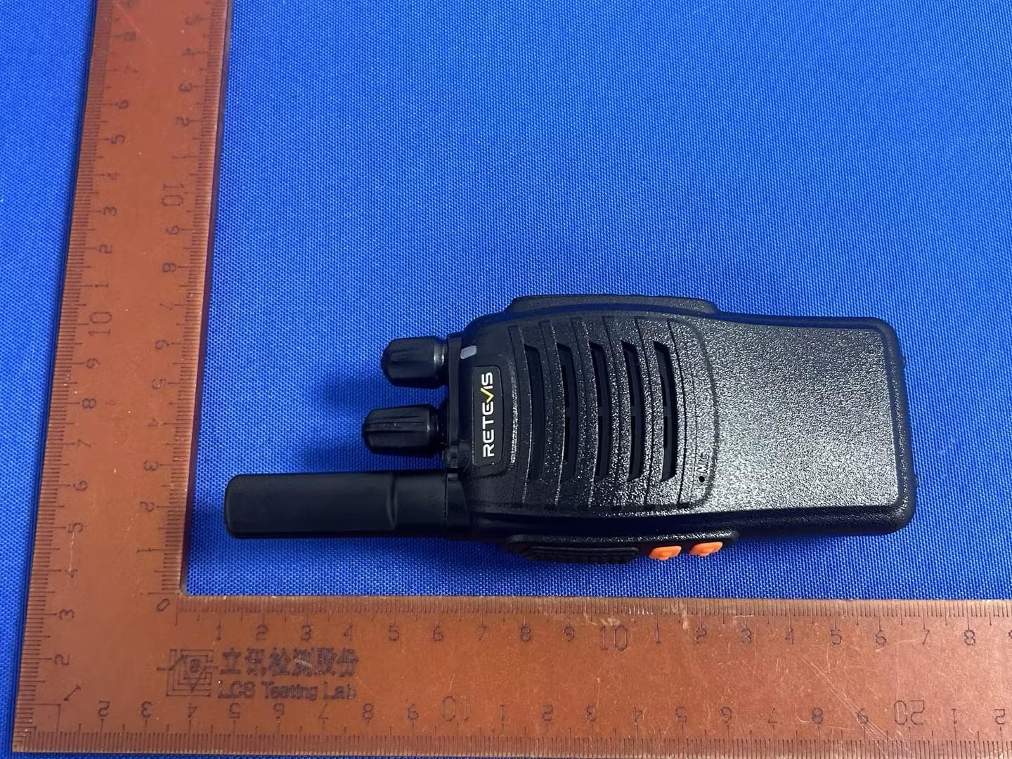
2A3OOH777H
Oct 11, 2024Two Way Radio
Equipment Class
FRF - Part 95 Family Radio Face Held Transmitter
2A3OORB48P
Aug 18, 2024Two Way Radio
Equipment Class
TNF - Licensed Non-Broadcast Transmitter Held to Face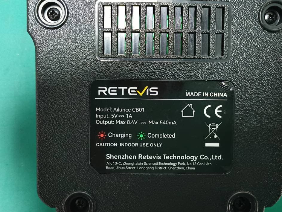
2A3OOHD2
May 20, 2024DMR Digital Transceiver
Equipment Class
DTS - Digital Transmission System
2A3OORTA1
May 01, 2024Amateur Radio
Equipment Class
CSR - Scanning Receiver2A3OO-P2
Apr 10, 2024Two Way Radio
Equipment Class
TNF - Licensed Non-Broadcast Transmitter Held to Face