2A3VP-Q17Wireless Gaming Controller
ShenZhen ShanWan Technology Co., Ltd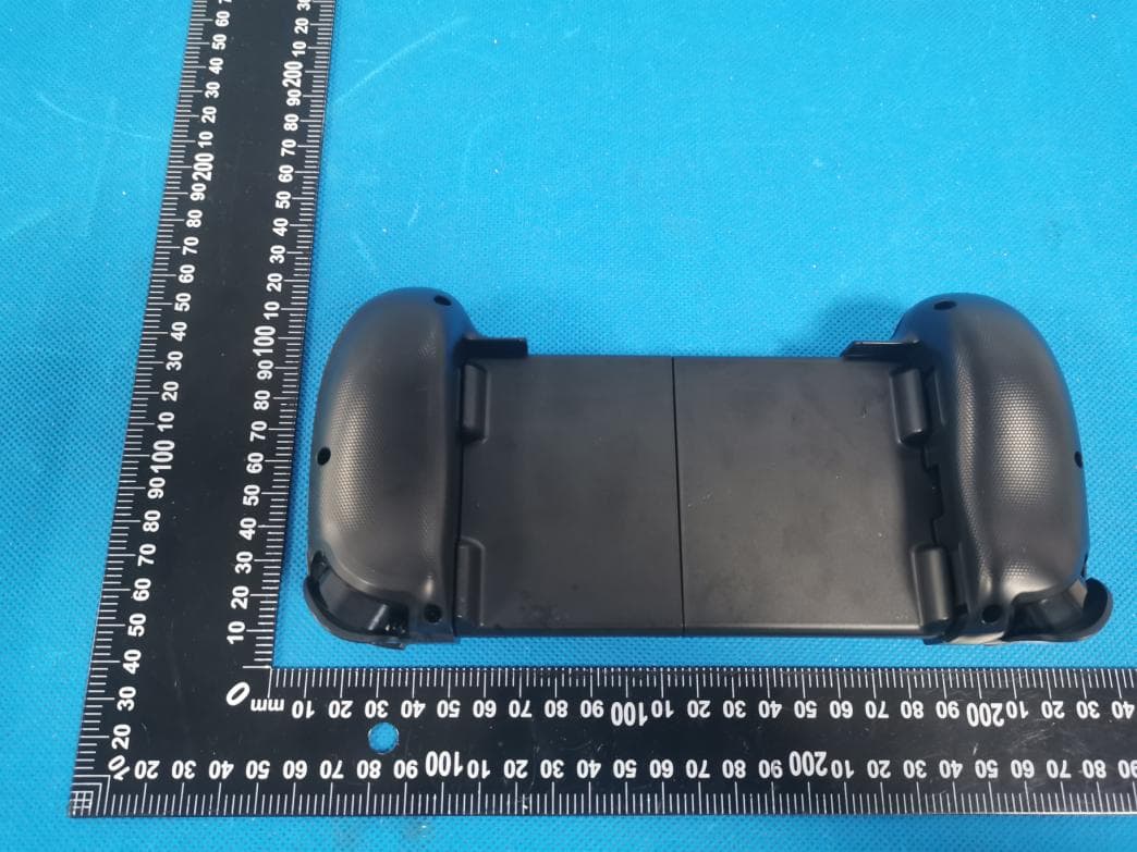
Click to zoom
Application Details
- Equipment Class
- DTS - Digital Transmission System
- Date of Grant
- Oct 25, 2023
- Application Purpose
- Original Equipment
- Date of Application
- Oct 25, 2023
- Equipment Note
- Wireless Gaming Controller
- Frequency Range
- 2402.00000000 - 2480.00000000
- Country
- China
Documents & Files
Document Text
Text extracted from the exhibit documents filed with the FCC. Open a document above to read the original.
Users Manual
Function buttons guide Left joystick/L3 Button Right joystick/R3 Button D-pad Button X/Y/B/A Button Power Button LED - Button + Button Screenshot Button Turbo Button Left Motor Right Motor Type-C Charging Port LB / LT Button RB / RT Button How to put the switch ?How to connection Switch and Switch OLED via Bluetooth? 1.On the switch console, select System Settings- >Controllers and Sensors- > Change Grip/Order to enter the switch console matched page. (If you need to change controller you can Press L + R button in connection controller.) 2.Hold botton keep 3 seconds. And then, the LEDs are blue and quick blink. After the connection is successful, LEDs are blue and keep bright. You can reconnect it by pressing the botton. The LEDs will blink slowly (1 second to light) and then connect back. How to turn off the controller? Press and hold button keep 5 seconds. Extended function: While connecting to the switch game console, the function can be expanded through the GamepadSpace APP on the mobile phone. Please scan the QR code above to download App. Q17 Game controller T button function: T button is “TURBO” function, A/B/X/Y/LB/LT/RB/LT can by ”TURBO” compiled into a basic button. How to set T button is A button Function? Press and hold A button, then press button to set Turbo. How to clear T button is A button Function? Press and hold A button again, then press button to clear Turbo. How to set 3 Speeds of T button? button + button = 25Hz TURBO speed / button + button = 12.5Hz TURBO speed button + button = 6.25Hz TURBO speed How to clear all T button function? Press and hold the button button for 5 seconds. Charging/Sleep/wake-up function Charging: When the battery is low, the LEDs is cyan and blinks (0.6 seconds to light) ; when charging, the LEDs will blink (3 seconds to light) ; When the battery is full, the LEDs will keep bright. Sleep: In pairing state, the controller will sleep if it is not paired successfully within 2 minutes. iOS SETP Line up your switch with controller's left side. SETP Grab the right handle and extend it. SETP 1 pushing 2 3 pushing Snap your Switch in. Notice 1. Don't store in a wet or high temperature place. 2. Don't throw it hard to avoid unnecessary damage. 3. Pay attention to garbage sorting. This product built-in battery. 4. Stay away from a fire and high temperature when it charging. 5. Non -professionals, please do not disassemble the controller by yourself, otherwise you will lose warranty. Q & A Q: How to adjust the height of the joystick? A: Rotate joystick clockwise can be adjusted lower,rotate joystick counterclockwise can be adjusted higher. Q: How to adjust the height of the back? A: The middle section can be pressed down. Connect back state: the controller will sleep if it is not connect back within 1 minutes. Bluetooth is connected state: the controller will sleep if the controller is not used within 15 minutes. Wake-up function Press the button to connect back when you need to wake-up it. Electrical parameters 1.Working voltage: DC3.7V 2. Working current: about 25mA 3. Working time: > 20H 4. Sleep current: < 10uA 5. Charging voltage/current: DC5V/500mA 6. Bluetooth transmission distance: < = 8M 7. Battery capacity: 600mA 8. Standby time: 90 days (fully charged) Controller Size Package list Q: Why the new controller can't power on? A: Because Battery died during transportation, please charge it first, connect the 5V charger with the USB cable in the packing box, until fully charged. Q: Joystick drift constantly. A: When the controller is turned off, press and hold the joystick vertically, and rotate 5 turns left and right. Q: Why the Switch console can't search the controller? A: Forget device name before you have connected and then reconnect. Q: Why can't reconnect when you press power button? A: Forget device name before you have connected and then reconnect. Q: The buttons don't work. A: Power off the controller and then repeat press button to power it up. Q: Bluetooth connection keep dropping and requires reconnect. A: 1) Reboot by long pressing the button. 2) If step 1) don't work, you can use a small pin to insert the small hole next to the charging port of the controller and press it once to reset the controller, then press and hold the power button again to turn it on. Product warning This device complies with part 15 of the FCC Rules. Operation is subject to the condition that this device does not cause harmful interference (1) this device may not cause harmful interference, and (2) this device must accept any interference received, including interference that may cause undesired operation. Any changes or modifications not expressly approved by the party responsible for compliance could void the user's authority to operate the equipment. Note: This equipment has been tested and found to comply with the limits for a Class B digital device, pursuant to Part 15 of the FCC Rules. These limits are designed to provide reasonable protection against harmful interference in a residential installation. This equipment generates, uses and can radiate radio frequency energy and, if not installed and used in accordance with the instructions, may cause harmful interference to radio communications. However, there is no guarantee that interference will not occur in a particular installation. If this equipment does cause harmful interference to radio or television reception,which can be determined by turning the equipment off and on, the user is encouraged to try to correct the interference by one or more of the following measures: -Reorient or relocate the receiving antenna. -Increase the separation between the equipment and receiver. -Connect the equipment into an outlet on a circuit different from that to which the receiver is connected. -Consult the dealer or an experienced radio/TV technician for help. The device has been evaluated to meet general RF exposure requirement. The device can be used in portable exposure condition without restriction. FCC ID:…
Text truncated - open the document above for the full version.
Attestation Statements
C5266091_X24_Ed.2 1/1 “Attestation Statements” TO: Office of Engineering Technology Federal Communications Commission 7435 Oakland Mills Road Columbia, MD 21046 The Commission adopted rules that prohibit equipment authorization for “covered” telecommunications equipment and video surveillance equipment produced by entities identified on the Commission’s Covered List 1 , which is periodically updated. See the Covered List for more details. This Attestation Statement is to confirm that we follow the Section 2.911(d)(5)(i)-(ii) Applicant Company name: ShenZhen ShanWan Technology Co., Ltd Grantee code: 2A3VP FCC ID: 2A3VP-Q17 Contact Name: XiaoChen Hu Address: 5 / F, building 33, chentian Industrial Zone, chentian community, Xixiang street, Bao'an District, Shenzhen, Guangdong China Telephone No: 0755-27941994 Fax No: 0755-27941994 Email: [email protected] i. [ShenZhen ShanWan Technology Co., Ltd] (“the applicant”) certifies that the equipment for which authorization is sought is not “covered” equipment prohibited from receiving an equipment authorization pursuant to section 2.903 of the FCC rules. The applicant must sign this certification. ii. [ShenZhen ShanWan Technology Co., Ltd] (“the applicant”) certifies that, as of the date of the filing of the application, the applicant is not (as a specifically named entity or any of its subsidiaries or affiliates) identified on the Covered List as an entity producing “covered” equipment. Theapplicantmustsignthiscertification. ShenZhen ShanWan Technology Co., Ltd certifies that, as of the date of the filing of theapplication, the applicant is notidentified on the Covered List as an entity producing “covered”equipment. Date: 24/10/2023 Applicant’s Name: XiaoChen Hu Title:General Manager Signature 1 The Commission’s Covered List is published by the Public Safety and Homeland Security Bureau and posted on the Commission’s website. This Covered List, which is periodically updated, identifies particular equipment, produced by particular entities, that constitutes “covered” equipment. https://www.fcc.gov/supplychain/coveredlist
Attestation Statements
ShenZhen ShanWan Technology Co., Ltd Family models declaration letter. 10/24/2023 We Company: ShenZhen ShanWan Technology Co., Ltd Address: 5 / F, building 33, chentian Industrial Zone, chentian community, Xixiang street, Bao'an District, Shenzhen, Guangdong China Product: Wireless Gaming Controller Model Name: Q17 Family Model: Q17S, Q17P, Q17X, Q17SP, Q17XP, Q17SX, Q17A, Q17B, Q17C, Q17W, Q133, Q133P, Q133X, Q133PX, Q15, Q15P, Q15X, Q15A, Q15B, Q15C, Q15W,Q18, Q18P, Q18X, Q18S, Q18SP, Q18W, D3, D5, D6, D7, D8, D9, D10 All models are the same circuit and RF module, except for different colors. We (ShenZhen ShanWan Technology Co., Ltd) hereby state that all the models are electrical identical including the same software parameter and hardware design (i.e., circuit design, PCB Layout, RF module/circuit, antenna type(s) and antenna location, components on PCB, etc.), same mechanical structure and design (including product enclosure, materials, etc.), the only difference is theAll the model are the same circuit and RF module, except the colors. Thanks Sincerely, Signature [Name] XiaoChen Hu [Title] Gernal manager [email protected]
Cover Letter(s)
C5266091_X8_Ed.1 1/1 Letter of Authorization < ShenZhen ShanWan Technology Co., Ltd > Company: ShenZhen ShanWan Technology Co., Ltd Address: 5 / F, building 33, chentian Industrial Zone, chentian community, Xixiang street, Bao'an District, Shenzhen, Guangdong China Product Name: Wireless Gaming Controller Model Number: Q17,Q17S, Q17P, Q17X, Q17SP, Q17XP, Q17SX, Q17A, Q17B, Q17C, Q17W, Q133, Q133P, Q133X, Q133PX, Q15, Q15P, Q15X, Q15A, Q15B, Q15C, Q15W,Q18, Q18P, Q18X, Q18S, Q18SP, Q18W, D3, D5, D6, D7, D8, D9, D10 FCC Identifier: 2A3VP-Q17 We authorize LGAI Technological Center S.A., Ronda de la Font del Carme, s/n, 08193 Bellaterra, Spain, to act on our behalf on all matters concerning the above named equipment. Any individual within LGAI Technological Center S.A. is authorized to act on our behalf and take action on the application. We declare that authorize LGAI Technological Center S.A., Ronda de la Font del Carme, s/n, 08193 Bellaterra, Spain, is allowed to forward all information related to the approval project to the Federal Communication Commission and to discuss any issues concerning the approval application. Any and all acts carried out by LGAI Technological Center S.A. on our behalf shall have the same effect as acts of our own. Name: XiaoChen Hu Date: 24/10/2023 Title: Manager Signature of applicant:
Cover Letter(s)
C5266091_X10_Ed.2 1/1 < ShenZhen ShanWan Technology Co., Ltd > Office of Engineering Technology Federal Communications Commission 7435 Oakland Mills Road Columbia, MD 21046 Date: 24/10/2023 Subject: Request for Confidentiality FCC ID: 2A3VP-Q17 To Whom It May Concern, Pursuant to the provisions of Sections 0.457 and 0.459 of Commission's rules (47CFR0.457, 0.459), we are requesting the Commission to withhold the following attachment(s) as confidential document from public disclosure. Exhibits Long-Term Confidentiality Short-Term Confidentiality NOTE 2 ID Label/Location Attestation Statement External Photos Block Diagram Schematics Test Report Test Setup Photos User’s Manual NOTE 1 Internal Photos NOTE 1 Parts List / Tune Up / BOM List RF Exposure Info Operational Description Cover Letter(s) FCC Software Security Requirements for UNII devices NOTE 1: Long-Term Confidentiality may be permitted under special conditions (See II. LONG-TERM CONFIDENTIALITY, Section 3 of KDB 726920, use last in force) NOTE 2: Short-Term Confidentiality can be requested for a maximum of 180 days from the date of the grant. Above mentioned document contains detailed system and equipment description are considered as proprietary information in operation of the equipment. The public disclosure of above documents might be harmful to our company and would give competitor an unfair advantage in the market. In case of short-term Confidentiality, the applicant requests the exhibits selected above are withheld from public view for a period of _180_ days from the date of the Grant of Equipment Authorization and prior to marketing. C5266091_X10_Ed.2 1/1 It is our understanding that all measurement test reports, FCC ID label format and correspondent during certification review process cannot be granted as confidential documents and those information will be available for public review once the grant of equipment authorization is issued. Sincerely, Signature: Name: XiaoChen Hu Title: Manager
External Photos
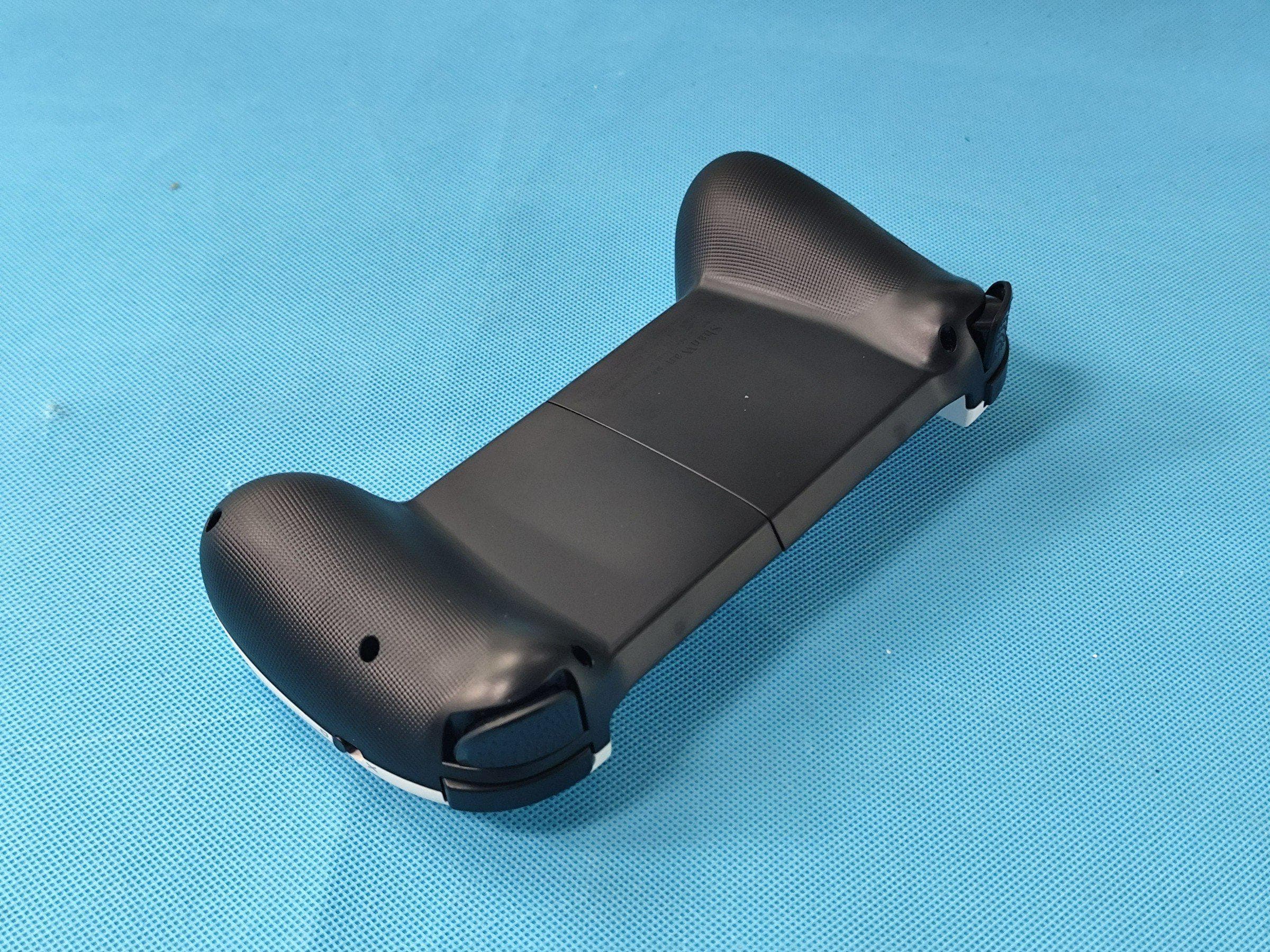
Photo 1 Photo 2 Photo 3 Photo 4 Photo 5 Photo 6 Photo 7
ID Label/Location Info
Q17-J001 2023.05.31 12.6mm 12mm Size:25mm Size:26mm 6mm 10mm
Internal Photos
Photo 1 Photo 2 Photo 3 Photo 4 BLE Left ANT1 Photo 5 Photo 6 BLE right ANT2 Photo 7 Photo 8 Photo 9 Photo 10
RF Exposure Info
FCC ID:2A3VP-Q17 Portable device According to §15.247(e)(i) and §1.1307(b)(1), systems operating under the provisions of this section shall be operated in a manner that ensures that the public is not exposed to radio frequency energy level in excess of the Commission’s guidelines. According to KDB447498 D01 General RF Exposure Guidance V06 The 1-g SAR and 10-g SAR test exclusion thresholds for 100 MHz to 6 GHz at test separation distances ≤ 50 mm are determined by: [(max. power of channel, including tune-up tolerance, mW)/(min. test separation distance, mm)]·[√f(GHZ)] ≤ 3.0 for 1-g SAR and ≤ 7.5 for 10-g extremity SAR, where: • f(GHZ) is the RF channel transmit frequency in GHz • Power and distance are rounded to the nearest mW and mm before calculation • The result is rounded to one decimal place for comparison When the minimum test separation distance is < 5 mm, a distance of 5 mm is applied to determine SAR test exclusion. BLE(Left) Antenna Type: PCB Antenna Antenna1 Gain: -0.71dBi Modulation Channel Freq. (GHz) Conduct ed power (dBm) Conducte d power (mW) Tune-up power (dBm) Max tune-up power (dBm) Max tune-up power (mW) Distance (mm) Result calculatio n 1g SAR Exclusion threshold SAR test exclusion 2.402-1.180.762-1±10.01.000<50.309973.00YES 2.44-1.130.771-1±10.01.000<50.312413.00YES 2.480-0.820.828-1±10.01.000<50.314963.00YES GFSK BLE(Right): Antenna Type: PCB Antenna Antenna2 Gain: 2.88dBi Modulation Channel Freq. (GHz) Conduct ed power (dBm) Conducte d power (mW) Tune-up power (dBm) Max tune-up power (dBm) Max tune-up power (mW) Distance (mm) Result calculatio n 1g SAR Exclusion threshold SAR test exclusion 2.402 1.11 1.2911±12.01.585<50.491273.00YES 2.44 1.54 1.4261±12.01.585<50.495143.00YES 2.480 1.16 1.3061±12.01.585<50.499183.00YES GFSK SIMULTANEOUS TRANSMISSIONS When a number of sources at different frequencies, and/or broadband sources, contribute to the total exposure, it becomes necessary to weigh each contribution relative to the MPE. To comply with the MPE, the fraction of the MPE in terms of E 2 , H 2 (or power density) incurred within each frequency interval should be determined and the sum of all such fractions should not exceed unity. In order to ensure compliance with the MPE for a controlled environment, the sum of the ratios of the power density to the corresponding MPE should not exceed unity. That is Transmitting Mode Result calculation 1g SAR Exclusion threshold Total S MPE Limit Conclusion BREDR 0.31496 3.00 0.27138 1.000 Pass BLE 0.49918 3.00 Conclusion: For the max result : 0.27138≤ 1, No SAR is required. Signature: Date: 10/26/2023 NAME AND TITLE (Please print or type): Alex /Manager COMPANY (Please print or type): Shenzhen NTEK Testing Technology Co., Ltd./ 1/F, Building E, Fenda Science Park, Sanwei Community, Xixiang Street Bao’an District, Shenzhen 518126 P.R. China
Test Report
ShenZhen ShanWan Technology Co., Ltd Antenna report 1.test philosophy ShanWan 2. test equipment name modle model numbei manufacturer calibration date Date of next calibration OTA test system RayZone- 5000 RFI-LAB-RF-D00GTS2021.3.222023.3.21 network analyzer E5071CRFI-LAB-RF-C02KEYSIGHT2022.5.132023.5.12 network analyzer E5071CRFI-LAB-RF-D01KEYSIGHT2022.5.132023.5.12 3. testing environment environment temperature 23.6°C re lative humidity 58%RH atmospheric pressure 100.14kPa ShanWan 4. Sample material 5. Sample layout diagram front view ShanWan 6.test result 6.1 detection principle Object name name of parameter Method name standard Mobile communication antenna radiation pattern General technical specification for mobile communication antennas GB/T 9410-2008 antenna gain voltage standing wav e ratio Roundness of the dir ectional graph antenna Gain and directivity IEEE Standard Procedure for antenna testing ANSI/IEEE Std 149-1979 r adiant efficiency impedance 6.2 Test uncertainty the calculation of Uncertainty is based on the "Guide to the Expression of Uncertainty in Measurement" (GUM) published by ISO, which uses K=2 inclusion factor and 95% confidence level to represent extended uncertainty. project uncertainty standing wave-ratio swr ±0.3 Gain, efficiency ±0.72dB ShanWan 7. test data 7.1 Network analyzer test 7.2 standing-wave ratio (SWR) f requency/MHz 240224402480 v oltage standing w ave ratio 2.74572.67232.3064 7.3 Gain and efficiency frequency/MHz 240224102420243024402450246024702480 maximum gain/dBi -1.97-1.95-1.63-1.49-1.27-1.06-0.89-0.71-0.95 efficiency/% 17.8818.3419.2019.8920.5820.8621.7822.1821.03 7.4 Directional artwork frequency/MHz 240224102420243024402450246024702480 H Theta=90/dB 20.5520.5720.1519.1218.9320.1120.4919.2616.51 ShanWan 7.5 directional diagram (1) X-Z 面(单位:dBi): (2) Y-Z (unit:dBi): ShanWan (3) X-Y (unit:dBi): (4) 2470MHz 的 3D directional diagram(unit:dBi): -------------------------------------------------end------------------------------------------------ (The following is blank)
Test Report
ShenZhen ShanWan Technology Co., Ltd Antenna report 1、essential information 1.1 test philosophy ShanWan 1.2 test equipment next name model equipment number manufacturer calibration date calibration date RayZone- 5000 OTAtest system RFI-LAB-RF-D00 GTS 2021.3.22 2023.3.21 network analyzer network analyzer E5071C E5071C RFI-LAB-RF-C02 RFI-LAB-RF-D01 KEYSIGHT KEYSIGHT 2022.5.13 2022.5.13 2023.5.12 2023.5.12 1.3 testing environment environment temperature relative humidity atmospheric pressure 23.7°C 58%RH 100.14kPa ShanWan 2. Sample drawing 3 Sample layout diagram front view ShanWan 3. front view 3.1 detection principle Object name name of parameter antenna pattern antenna gain Method name By standard number Mobile communicatio n antenna General technical specification for mobile communication antennas GB/T 9410-2008 voltage standing wave ratio Roundness of the directional graph Gain and directivity impedance: ANSI/IEEE Std 149-1979 antenna IEEE Standard Procedure for antenna testing 3.2Test uncertainty the calculation of Uncertainty is based on the "Guide to the Expression of Uncertainty in Measurement" (GUM) published by ISO, which uses K=2 inclusion factor and 95% confidence level to represent extended uncertainty. item standing-wave ratio uncertainty ±0.3 Gain, efficiency ±0.72dB emission efficiency ShanWan 3.3test data 3.3.1Network analyzer test 3.3.2standing-wave ratio 2402 2440 2480 voltage standing wave ratio /MHz 1.3910 1.4662 2.0735 3.3Gain and efficiency frequency/MHz / maximum gaindBi efficiency/% 2402 2.85 2410 2.88 2420 2.79 2430 2.77 2440 2.69 2450 2.52 2460 2.46 2470 2.41 2480 2.03 44.98 45.34 44.93 45.74 46.00 45.14 45.56 44.49 40.81 3.3.4Roundness of the directional graph frequency/MHz 2402 2410 2420 2430 2440 2450 2460 2470 2480 H Theta=90/dB 14.22 14.43 14.31 13.68 13.38 13.30 13.18 13.31 13.58 QP030-41 第 8页共 10页 frequency/MHz ShanWan 3.3.5 directional diagram (1) X-Z( unit:dBi): (2) Y-Z( unit:dBi): ShanWan (3) X-Y( unit:dBi): (4) 2410MHz的 3D directional diagram( unit:dBi): -------------------------------------------------结束------------------------------------------------ (以下内容空白)
Test Report
Report No.: S23060905205001 Version.1.3 Page 1 of 63 RADIO TEST REPORT FCC ID: 2A3VP-Q17 Product: Wireless Gaming Controller Trade Mark: N/A Model No.: Q17 Family Model: Q17S, Q17P, Q17X, Q17SP, Q17XP, Q17SX, Q17A, Q17B, Q17C, Q17W, Q133, Q133P, Q133X, Q133PX, Q15, Q15P, Q15X, Q15A, Q15B, Q15C, Q15W, Q18, Q18P, Q18X, Q18S, Q18SP, Q18W, D3, D5, D6, D7, D8, D9, D10 Report No.: S23060905205001 Issue Date: Oct 09, 2023 Prepared for ShenZhen ShanWan Technology Co., Ltd 5 / F, building 33, chentian Industrial Zone, chentian community, Xixiang street, Bao'an District, Shenzhen, Guangdong Prepared by Shenzhen NTEK Testing Technology Co., Ltd. 1/F, Building E, Fenda Science Park, Sanwei Community,Xixiang Street Bao’an District, Shenzhen 518126 P.R. China Tel. 400-800-6106, 0755-2320 0050, 0755-2320 0090 Website: http://www.ntek.org.cn Report No.: S23060905205001 Version.1.3 Page 2 of 63 TABLE OF CONTENTS 1 TEST RESULT CERTIFICATION ...................................................................................................................... 4 2 SUMMARY OF TEST RESULTS ......................................................................................................................... 5 3 FACILITIES AND ACCREDITATIONS ............................................................................................................. 6 3.1 FACILITIES..................................................................................................................................................... 6 3.2 LABORATORY ACCREDITATIONS AND LISTINGS ................................................................................. 6 3.3 MEASUREMENT UNCERTAINTY ............................................................................................................... 6 4 GENERAL DESCRIPTION OF EUT .................................................................................................................. 7 5 DESCRIPTION OF TEST MODES ..................................................................................................................... 9 6 SETUP OF EQUIPMENT UNDER TEST ......................................................................................................... 10 6.1 BLOCK DIAGRAM CONFIGURATION OF TEST SYSTEM ..................................................................... 10 6.2 SUPPORT EQUIPMENT............................................................................................................................... 11 6.3 EQUIPMENTS LIST FOR ALL TEST ITEMS .............................................................................................. 12 7 TEST REQUIREMENTS .................................................................................................................................... 14 7.1 CONDUCTED EMISSIONS TEST ............................................................................................................... 14 7.1.1 Applicable Standard .................................................................................................................................. 14 7.1.2 Conformance Limit ................................................................................................................................... 14 7.1.3 Measuring Instruments............................................................................................................................. 14 7.1.4 Test Configuration .................................................................................................................................... 14 7.1.5 Test Procedure ........................................................................................................................................... 14 7.1.6 Test Results ................................................................................................................................................ 15 7.2 RADIATED SPURIOUS EMISSION ............................................................................................................ 19 7.2.1 Applicable Standard .................................................................................................................................. 19 7.2.2 Conformance Limit ................................................................................................................................... 19 7.2.3 Measuring Instruments............................................................................................................................. 20 7.2.4 Test Configuration .................................................................................................................................... 20 7.2.5 Test Procedure ........................................................................................................................................... 21 7.2.6 Test Results ................................................................................................................................................ 22 7.3 6DB BANDWIDTH ....................................................................................................................................... 31 7.3.1 Applicable Standard .................................................................................................................................. 31 7.3.2 Conformance Limit ................................................................................................................................... 31 7.3.3 Measuring Instruments............................................................................................................................. 31 7.3.4 Test Setup .................................................................................................................................................. 31 7.3.5 Test Procedure ........................................................................................................................................... 31 7.3.6 Test Results ..........…
Text truncated - open the document above for the full version.
Test Setup Photos
Radiated Measurement Photos Conducted Measurement Photos
Contact Information
Applicant
XiaoChen Hu
Technical Contact
Non-Technical Contact
Shenzhen NTEK Testing Technology Co., Ltd.Alex Li
[email protected]86-755-6115 6588
Test Firm
Shenzhen NTEK Testing Technology Co., Ltd.Alex Li
[email protected]+86-755-6115-9384
Technical Specifications
| # | Rule Parts | Frequency Range | Power Output |
|---|---|---|---|
| 1 | 15C | 2.40 GHz - 2.48 GHz | 1.43 mW |
Other Applications from ShenZhen ShanWan Technology Co., Ltd
2A3VP-Q13L
May 12, 2026Mobile Game Controller
Equipment Class
DTS - Digital Transmission System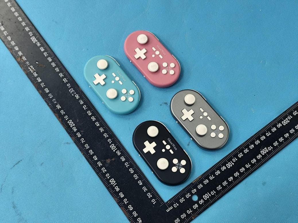
2A3VP-Q37PA
Mar 30, 2026Wireless Gaming Controller
Equipment Class
DTS - Digital Transmission System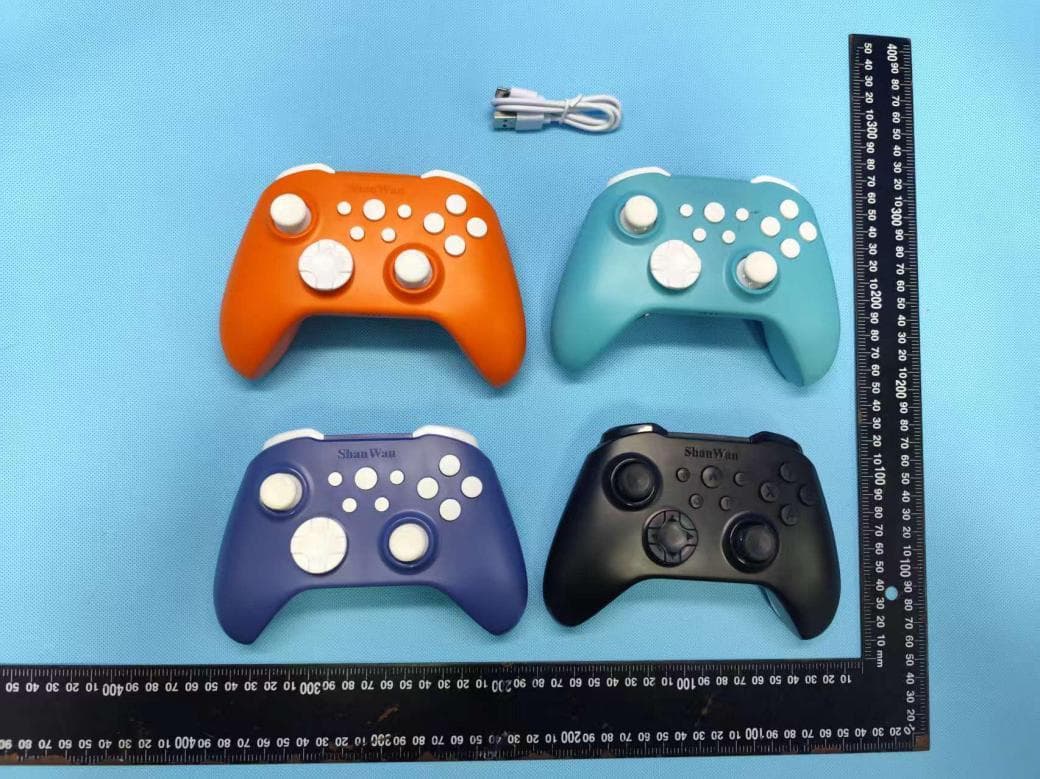
2A3VP-Q34B
Sep 15, 2025Wireless Gaming Controller
Equipment Class
DTS - Digital Transmission System
2A3VP-Q38
Dec 01, 2024Wireless Gaming Controller
Equipment Class
DTS - Digital Transmission System
2A3VP-Q41
Jun 26, 2023Wireless Gaming Controller
Equipment Class
DTS - Digital Transmission System