2A4FR-LSE-6WStick Logger(Ethernet)
IGEN TECH CO.,Ltd.
Click to zoom
Application Details
- Equipment Class
- DTS - Digital Transmission System
- Date of Grant
- Jul 13, 2026
- Application Purpose
- Original Equipment
- Equipment Note
- Stick Logger(Ethernet)
- Frequency Range
- 2402.00000000 - 2480.00000000
- Company
- IGEN TECH CO.,Ltd.
- Country
- China
Documents & Files
Document Text
Text extracted from the exhibit documents filed with the FCC. Open a document above to read the original.
Users Manual
Stick Logger Quick Guide Model:LSE-�W Notice: Please read this manual carefully before using products and keep it in the place where O&M providers can easily find. Due to product upgrade and other factors, the content of this manual might change from time to time. Please take actual product as standard and get latest manual from the sales department. Unless otherwise agreed herein, this manual will only be used as guidance. Any statement, information or suggestion in this manual will not take any form of responsibility. Without written permission, any content of this document (partly or entirely) cannot be extracted, copied or transmitted in any form by any company or individual. �. Stick Logger Installation Step �: Remove the bottom plug of the stick logger's main housing,thread the Ethernet cable through the accessory and the sealing ring. Step �: Insert the RJ�� connector into the main housing, then snap the accessory and the main housing together until a "click" is heard, then press the sealing ring tightly into place at the bottom. �. Logger Status IndicatorImplicationStatus Description Logger running status Communication with inverter Communication with server �. Light stays on/off: Running abnormally. �. On �s/Off �s (Slow flash): Running normally. �. Light stays on: Logger connected to the inverter. �. Light off: Connection to the inverter failed. �. On �s/Off �s: Communicating with inverter. �. On ���ms/Off �s (Slow flash): Connection to the router failed. �. On �s/Off �s: Connection to the router succeeded. �. Light stays on: Connection to the server succeeded. READY COM SER �. Registration APP USER MANUAL Click "Register" to create new account. You can use email to register. �.� Click "Start" to create your home on SOLARMAN Smart. If you have already created a home, you will not see the following page. And if you wish to create another home, please click "+" in the upper-right corner and select "Add Home". �. Create a home 17000184 Warning: Please remove the logger after powering it off. ! �. Network cable installation Bottom Plug Accessory Sealing Ring iPhone: Search "SOLARMAN Smart" or "SOLARMAN Business" in APP Store. Android: Search "SOLARMAN Smart" or "SOLARMAN Business" in Google Play. Download APP SOLARMAN Smart for end userSOLARMAN Business for O&M provider and installer Type �: USB port � Assemble the logger to the inverter communication interface as shown in the diagram. ! Warning: Please do not hold the logger body to rotate it while installing or removing it. click ! �.Connect to Router Connect another end of network line to LAN Interface. DHCP:Obtain IP address automatically WANLAN Type �: Small and large aviation connector port Small aviation connector port Large aviation connector port Type �: USB port �Type �: DB� port ! Warning: Do not invert the stick logger during installation. WARRANTY CARD �.� Enter Home Details Please enter detailed home information according to your actual situation. System will create an unique home for you. In order to calculate plant data precisely, please enter ● Home Name, ● Home Type, ● Grid Type, ● Home Location, ● Other information. You can click the right icon to switch between �D Plan and Satellite Map. �. Add a Logger �.� Select a home �)Go to the"Home"page , select a home according to your actual situation in the upper-left corner, then click "+" in the upper-right corner, select "Add device". �)Go to the"Device"page , click "Start" to add a logger to the target home. �.� Enter Logger SN Users can enter the logger SN manually or click icon to scan the SN. ! Warning: Please make sure the stick logger is working properly before you leave the site. If there is anything abnormal, please do not leave the site and contact customer service as soon as possible. If you have any technical queries about our products, please contact us and provide the following information: �. Product model and serial number of the stick logger. �. Product model and serial number of the connected inverter. Thank you for your support and cooperation! Dear Customers, Thank you very much for using our products. In order to provide you with better service, please fill in the warranty card and reserve it carefully. User NameCustomer Name Customer Phone Product SN Purchase Date Product Name &Model Customer Address Order No. Maintenance Records DateFailure Cause and Treatment Warranty Policy If there is any breakdown which caused by the product's own quality. customers can send the warranty card with the product to our Customer Service Center. Notice �. According to the prescription, the warranty period is � years (From the day when you receive the product). During the warranty period, we provide free maintenance service to solve all non-artificial quality problems if the product is under normal usage circumstance. If the product exceeds the warranty period, only maintenance cost will be charged. �. If the failure of the product is not due to quality problems (such as improper use, improper storage, unauthorized disassembly, etc.), maintenance cost will be charged. �. Please pay for back goods freight in advance. Freight collect is not accepted. Support Email: [email protected] Customer Hotline: +�� ��� ��� ���� Company Address: Building H�, China IoT International Innovation Park, No. �, Jingxian Road, Wuxi, Jiangsu, P. R. China �. WiFi Connection Configuration Scan the logger SN, then connect it to the same WiFi network as the mobile phone. Click "Set Up" and wait for the configuration to complete. If "Set Up Later" is selected, you can go to the device page later to configure the device. If configuration failure occurs, please check the following reasons and try it again. �. Make sure WLAN is ON; �. Make sure WiFi is normal; �. Make sure wireless router does not implement the white-black list; �. Shorten the distance between the phone and device; �. Try to connect to other WiFi; �. Remove the special characters(,;‘ ’=“ ”`) in WiFi network; �. Ch…
Text truncated - open the document above for the full version.
Attestation Statements
IGEN TECH CO.,Ltd. June 25, 2026 Eurofins Electrical and Electronic Testing NA, Inc. 914 West Patapsco Avenue Baltimore, MD 21230 RE: Attestation Statements Part 2.911(d)(5)(i) request for FCC ID: 2A4FR-LSE-6W IGEN TECH CO.,Ltd. (“the applicant”) certifies that the equipment for which authorization is sought is not “covered” equipment prohibited from receiving an equipment authorization pursuant to section 2.903 of the FCC rules. We also certify that, as of the date of the filing of the application, the equipment does not utilize cyber-security or anti-virus software from Kaspersky Lab, Inc, or any of its successors and assignees, which is also on the “covered list”. Sincerely, (Applicant signature) shi chen Design Quality Engineer IGEN TECH CO.,Ltd. IGEN TECH CO.,Ltd. June 25, 2026 Eurofins Electrical and Electronic Testing NA, Inc. 914 West Patapsco Avenue Baltimore, MD 21230 RE: Attestation Statements Part 2.911(d)(5)(ii) request for FCC ID: 2A4FR-LSE-6W IGEN TECH CO.,Ltd. (“the applicant”) certifies that, as of the date of the filing of the application, the applicant is not identified on the Covered List as an entity producing “covered” equipment. Sincerely, (Applicant signature) shi chen Design Quality Engineer IGEN TECH CO.,Ltd.
External Photos
Appendix-LSE-6W-Photos Reference No.: WTH26D05135550W Page 3 of 9 2. Photographs –Constructional Details 2.1. EUT – External View Model LSE-6W FCC ID: 2A4FR-LSE-6W Appendix-LSE-6W-Photos Reference No.: WTH26D05135550W Page 4 of 9 Appendix-LSE-6W-Photos Reference No.: WTH26D05135550W Page 5 of 9 Appendix-LSE-6W-Photos Reference No.: WTH26D05135550W Page 6 of 9
Internal Photos
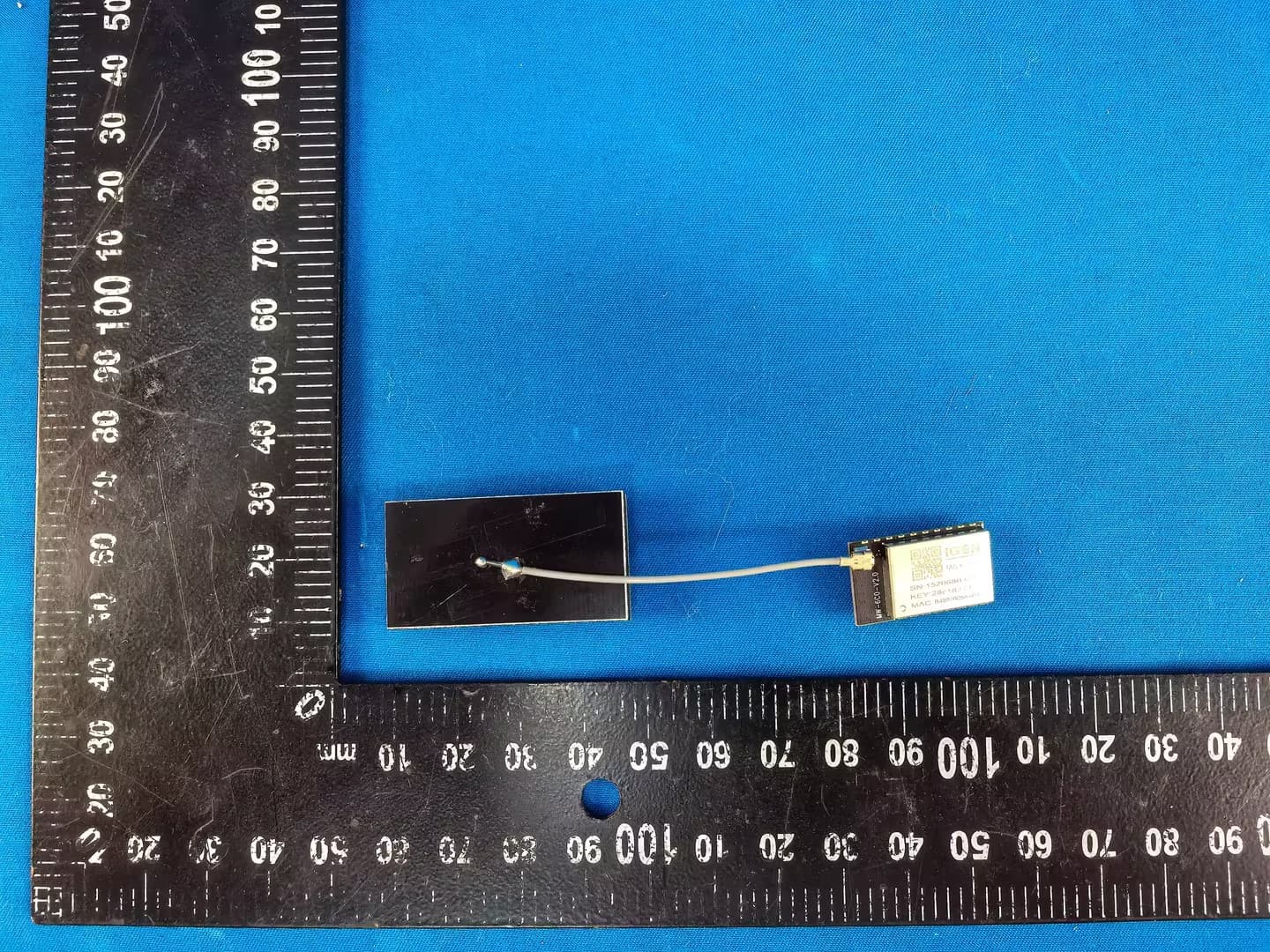
Appendix-LSE-6W-Photos Reference No.: WTH26D05135550W Page 7 of 9 2.2. EUT – Internal View Model LSE-6W FCC ID: 2A4FR-LSE-6W Appendix-LSE-6W-Photos Reference No.: WTH26D05135550W Page 8 of 9 Antenna Appendix-LSE-6W-Photos Reference No.: WTH26D05135550W Page 9 of 9 ======End======
RF Exposure Info
Waltek Testing Group Co., Ltd. http://www.waltek.com.cn Page 1 of 8 TEST REPORT Referen ce No. .................... : WTH26D05135550W004 FCC ID ................................ : 2A4FR-LSE-6W Applicant ............................ : IGEN Tech Co., Ltd. Address .............................. : Block F4, No. 200, Linghu Avenue, Wuxi, Jiangsu, P. R. China, 225400 Manufacturer .................... : IGEN Tech Co., Ltd. Address ............................. : Block F4, No. 200, Linghu Avenue, Wuxi, Jiangsu, P. R. China, 225400 Product ............................... : Stick Logger(Ethernet) Model(s). ............................ : LSE-6W Standards........................... : FCC 47CFR Part 2 Subpart J Section 2.1091 Date of Receipt Sample .... : 2026-05-25 Date of Test ....................... : 2026-06-10 to 2026-06-22 Date of Issue ...................... : 2026-07-07 Test Result ......................... : Pass Remarks: The re sults shown in this test report refer only to the sample(s) tested, this test report cannot be reproduced, except in full, without prior written permission of the company. The report would be invalid without specific stamp of test institute and the signatures of compiler and approver. Prepared By: Waltek Testing Group Co., Ltd. Address: No. 77, Houjie Section, Guantai Road, Houjie Town, Dongguan City, Guangdong, China Tel: +86-769-2267 6998 Fax: +86-769-2267 6828 Compiled by: Approved by: Frank Yin / Project Engineer Deval Qin / Designated Reviewer Reference No.: WTH26D05135550W004 Page 2 of 8 Waltek Testing Group Co., Ltd. http://www.waltek.com.cn 2. Contents Page 1 COVER PAGE ........................................................................................................................................... 1 2. CONTENTS ............................................................................................................................................................ 2 3. REVISION HISTORY ............................................................................................................................................ 3 4. GENERAL INFORMATION .................................................................................................................................. 4 4.1. GENERAL DESCRIPTION OF E.U.T. ............................................................................................................ 4 4.2. DETAILS OF E.U.T. ..................................................................................................................................... 4 4.3. TEST FACILITY ............................................................................................................................................ 5 4.4. SUBCONTRACTED ....................................................................................................................................... 5 4.5. ABNORMALITIES FROM STANDARD CONDITIONS ....................................................................................... 5 5. TEST SUMMARY .................................................................................................................................................. 6 6. RF EXPOSURE ...................................................................................................................................................... 7 6.1. REQUIREMENTS .......................................................................................................................................... 7 6.2. THE PROCEDURES / LIMIT ........................................................................................................................... 7 6.3. MPE CALCULATION METHOD .................................................................................................................... 8 6.4. RADIO FREQUENCY RADIATION EXPOSURE EVALUATION ......................................................................... 8 Reference No.: WTH26D05135550W004 Page 3 of 8 Waltek Testing Group Co., Ltd. http://www.waltek.com.cn 3. Revision History Test Report No. Date of Receipt Sample Date of Test Date of Issue Purpose CommentApproved WTH26D05135550W004 2026-05-25 2026-06-10 to 2026-06-22 2026-07-07Original - Valid Reference No.: WTH26D05135550W004 Page 4 of 8 Waltek Testing Group Co., Ltd. http://www.waltek.com.cn 4. General Information 4.1. General Description of E.U.T. Product:Stick Logger(Ethernet) Model(s):LSE-6W Model Description: N/A Test Sample No.: 1-1/1 Wi-Fi Specification: 802.11b/g/n HT20/n HT40/ax HE20 Bluetooth Version: V5.0 Hardware Version: LSE-6W Software Version: V1.3.0A 4.2. Details of E.U.T. Operation Frequency: LE: 2402-2480MHz, 40 Channels in total 2.4G Wi-Fi: 802.11b/g/n HT20/ax HE20: 2412~2462MHz 802.11n HT40: 2422~2452MHz Max. RF output power: LE 1M: 7.96dBm, LE 2M: 7.99dBm 2.4G Wi-Fi: 16.87dBm Modulation Technology: LE: GFSK 2.4G Wi-Fi: DSSS, OFDM Antenna installation: PCB printed antenna Antenna Gain: 3.0dBi Note: #: The antenna gain is provided by the applicant, and the applicant should be responsible for its authenticity, WALTEK lab has not verified the authenticity of its information. Ratings: DC 5V-12V, 1.5W Reference No.: WTH26D05135550W004 Page 5 of 8 Waltek Testing Group Co., Ltd. http://www.waltek.com.cn 4.3. Test Facility The test facility has a test site registered with the following organizations: ISED CAB identifier: CN0013. Test Firm Registration No.: 7760A. Waltek Testing Group Co., Ltd. Has been registered and fully described in a report filed with the Industry Canada. The acceptance letter from the Industry Canada is maintained in our files. Registration number 7760A, October 15, 2016. FCC Designation No.: CN1201. Test Firm Registration No.: 523476. Waltek Testing Group Co., Ltd. EMC Laboratory has been registered and fully described in a report filed with the (FCC) Federal Communications Commission. The acceptance letter from the FCC is maintained in our files. Registration number 523476, September 10, 2019. …
Text truncated - open the document above for the full version.
Test Report
MW-6-N-311 — Antenna Dimension Drawing English Translation of Original Chinese Technical Drawing 1. Original Drawing Figure 1: Original antenna dimension drawing (MW-6-N-311) 2. Drawing Overview This document is an English translation of the technical dimension drawing for the MW-6-N-311 antenna. The original drawing is a mechanical engineering diagram showing a rod/dipole antenna with an N-type connector base, presented in front (elevation) view and bottom view. Key components visible in the drawing: Radiating element (top rod section) Base housing N-type male connector at bottom Mounting thread interface 3. Electrical Specifications Parameter Value Frequency Range 2400–2500 MHz / 5150–5850 MHz (dual- band) Impedance 50 Ω Polarization Vertical Gain 3 dBi / 5 dBi VSWR ≤ 2.0 Power Handling 10 W 4. Mechanical Dimensions Dimension Value Tolerance Total Height 210.0 mm ± 1.0 mm Radiator Length 130.0 mm IT12 Base Height 80.0 mm IT12 Radiator Outer Diameter Ø 12.0 mm IT12 Base Outer Diameter Ø 22.0 mm IT12 Mounting Hole Diameter — — Weight — — 5. Connector Specification Parameter Value Type N-type Male (N-J) Mounting Thread N connector thread Installation Torque 2.0 ± 0.3 N·m 6. Material & Finish Item Specification Radiator Material Brass / Copper alloy (H62 Brass) Base Material Brass (H62 Brass) Surface Finish Nickel plated Color White or Black Sealing Method Epoxy potting 7. Environmental Ratings Parameter Value Operating Temperature -40°C ~ +85°C 8. General Notes 1. Undimensioned tolerances shall be per IT12 grade. 2. All dimensions are in millimeters (mm). 3. Surface shall be free from scratches, oxidation, and other defects. 4. Antenna shall be mounted vertically. 5. Connector installation torque: 2.0 ± 0.3 N·m. 9. Title Block Information Field Content Drawing Title Antenna Dimension Drawing Drawing No. MW-6-N-311 Revision A Scale 1:1 Material H62 Brass Designed by FN-LINK TECHNOLOGY LIMITED Reviewed by — Approved by — — End of Document — Translation completed: 2026-07-02 | Original: MW-6-N-311 -天线尺寸图.pdf
Test Report
Waltek Testing Group Co., Ltd. http://www.waltek.com.cn Page 1 of 38 TEST REPORT Referen ce No. .................... : WTH26D05135550W002 FCC ID ................................ : 2A4FR-LSE-6W Applicant ............................ : IGEN Tech Co., Ltd. Address .............................. : Block F4, No. 200, Linghu Avenue, Wuxi, Jiangsu, P. R. China, 225400 Manufacturer .................... : IGEN Tech Co., Ltd. Address ............................. : Block F4, No. 200, Linghu Avenue, Wuxi, Jiangsu, P. R. China, 225400 Product ............................... : Stick Logger(Ethernet) Model(s). ............................ : LSE-6W Standards........................... : FCC 47CFR Part 15.247 Date of Receipt sample .... : 2026-05-25 Date of Test ....................... : 2026-06-10 to 2026-06-22 Date of Issue ...................... : 2026-07-07 Test Result ......................... : Pass Remarks: The re sults shown in this test report refer only to the sample(s) tested, this test report cannot be reproduced, except in full, without prior written permission of the company. The report would be invalid without specific stamp of test institute and the signatures of compiler and approver. Prepared By: Waltek Testing Group Co., Ltd. Address: No. 77, Houjie Section, Guantai Road, Houjie Town, Dongguan City, Guangdong, China Tel: +86-769-2267 6998 Fax: +86-769-2267 6828 Compiled by: Approved by: Frank Yin / Project Engineer Deval Qin / Designated Reviewer Reference No.: WTH26D05135550W002 Page 2 of 38 Waltek Testing Group Co., Ltd. http://www.w altek.com.cn 2 Contents Page 1 COVER PAGE ........................................................................................................................................... 1 2 CONTENTS ............................................................................................................................................... 2 3 REVISION HISTORY ................................................................................................................................. 4 4 GENERAL INFORMATION ....................................................................................................................... 5 4.1 General Description of E.U.T. ....................................................................................................... 5 4.2 Details of E.U.T. ............................................................................................................................ 5 4.3 Channel List .................................................................................................................................. 5 4.4 Test Facility ................................................................................................................................... 6 4.5 Subcontracted ............................................................................................................................... 6 4.6 Abnormalities from Standard Conditions ...................................................................................... 6 4.7 Test Mode ..................................................................................................................................... 6 5 TEST SUMMARY ...................................................................................................................................... 7 6 EQUIPMENT USED DURING TEST ......................................................................................................... 8 6.1 Equipments List ............................................................................................................................ 8 6.2 Description of Support Units ......................................................................................................... 9 6.3 Measurement Uncertainty ............................................................................................................ 9 6.4 Test Equipment Calibration .......................................................................................................... 9 7 CONDUCTED EMISSION ....................................................................................................................... 10 7.1 E.U.T. Operation ......................................................................................................................... 10 7.2 EUT Setup .................................................................................................................................. 10 7.3 Measurement Description ........................................................................................................... 10 7.4 Conducted Emission Test Result ............................................................................................... 11 8 RADIATED EMISSIONS ......................................................................................................................... 13 8.1 EUT Operation ............................................................................................................................ 13 8.2 Test Setup .................................................................................................................................. 14 8.3 Spectrum Analyzer Setup ........................................................................................................... 15 8.4 Test Procedure ........................................................................................................................... 16 8.5 Corrected Amplitude & Margin Calculation ................................................................................ 16 8.6 Summary of Test Results ........................................................................................................... 17 9 CONDUCTED SPURIOUS EMISSIONS ................................................................................................. 20 9.1 Test Procedure ..................................................................…
Text truncated - open the document above for the full version.
Test Report
Waltek Testing Group Co., Ltd. http://www.waltek.com.cn Page 1 of 65 TEST REPORT Referen ce No. .................... : WTH26D05135550W003 FCC ID ................................ : 2A4FR-LSE-6W Applicant ............................ : IGEN Tech Co., Ltd. Address .............................. : Block F4, No. 200, Linghu Avenue, Wuxi, Jiangsu, P. R. China, 225400 Manufacturer .................... : IGEN Tech Co., Ltd. Address .............................. : Block F4, No. 200, Linghu Avenue, Wuxi, Jiangsu, P. R. China, 225400 Product ............................... : Stick Logger(Ethernet) Model(s). ............................ : LSE-6W Standards........................... : FCC 47CFR Part 15.247 Date of Receipt Sample .... : 2026-05-25 Date of Test ....................... : 2026-06-10 to 2026-06-22 Date of Issue ...................... : 2026-07-07 Test Result ......................... : Pass Remarks: The re sults shown in this test report refer only to the sample(s) tested, this test report cannot be reproduced, except in full, without prior written permission of the company. The report would be invalid without specific stamp of test institute and the signatures of compiler and approver. Prepared By: Waltek Testing Group Co., Ltd. Address: No. 77, Houjie Section, Guantai Road, Houjie Town, Dongguan City, Guangdong, China Tel: +86-769-2267 6998 Fax: +86-769-2267 6828 Compiled by: Approved by: Frank Yin / Project Engineer Deval Qin / Designated Reviewer Reference No.: WTH26D05135550W003 Page 2 of 65 Waltek Testing Group Co., Ltd. http://www.waltek.com.cn 2 Contents Page 1 COVER PAGE ........................................................................................................................................... 1 2 CONTENTS ............................................................................................................................................... 2 3 REVISION HISTORY ................................................................................................................................. 4 4 GENERAL INFORMATION ....................................................................................................................... 5 4.1 GENERAL DESCRIPTION OF E.U.T. ....................................................................................................... 5 4.2 DETAILS OF E.U.T. .............................................................................................................................. 5 4.3 CHANNEL LIST ..................................................................................................................................... 5 4.4 TEST FACILITY .................................................................................................................................... 6 4.5 SUBCONTRACTED ................................................................................................................................ 6 4.6 ABNORMALITIES FROM STANDARD CONDITIONS .................................................................................... 6 4.7 TEST MODE ........................................................................................................................................ 7 5 TEST SUMMARY ...................................................................................................................................... 8 6 EQUIPMENT USED DURING TEST ......................................................................................................... 9 6.1 EQUIPMENTS LIST ............................................................................................................................... 9 6.2 DESCRIPTION OF SUPPORT UNITS ...................................................................................................... 10 6.3 MEASUREMENT UNCERTAINTY ........................................................................................................... 10 6.4 TEST EQUIPMENT CALIBRATION ......................................................................................................... 10 7 DUTY CYCLE .......................................................................................................................................... 11 8 CONDUCTED EMISSION ....................................................................................................................... 14 8.1 E.U.T. OPERATION ............................................................................................................................ 14 8.2 EUT SETUP ...................................................................................................................................... 14 8.3 MEASUREMENT DESCRIPTION ............................................................................................................ 14 8.4 CONDUCTED EMISSION TEST RESULT ................................................................................................ 15 9 RADIATED EMISSIONS ......................................................................................................................... 17 9.1 EUT OPERATION ............................................................................................................................... 17 9.2 TEST SETUP ..................................................................................................................................... 18 9.3 SPECTRUM ANALYZER SETUP ............................................................................................................ 19 9.4 TEST PROCEDURE ............................................................................................................................. 20 9.5 CORRECTED AMPLITUDE & MARGIN CALCULATION .............................................................................. 20 9.6 SUMMARY OF TEST RESULTS ............................................................................................................. 21 10 CONDUCTED SPURIOUS EMISSIONS ...…
Text truncated - open the document above for the full version.
Test Setup Photos
Appendix-LSE-6W-Photos Reference No.: WTH26D05135550W Page 1 of 9 1. Test Setup photos Model LSE-6W FCC ID: 2A4FR-LSE-6W 1.1 Photograph – Conducted Emission For Conducted Emission Test Site 1# 1.2 Photograph – Radiated Emissions For 9kHz-30MHz Test Site 2# Appendix-LSE-6W-Photos Reference No.: WTH26D05135550W Page 2 of 9 For 30MHz-1000MHz Test Site 2# For Above 1GHz Test Site 1#
Contact Information
Applicant
shi chen
[email protected]Fax: +86 400-181-0512
Technical Contact
FCC US Agent, LLCTim Payne
3722 Illinois Avenue, · Saint Charles, Illinois, 60174 · United States
Test Firm
WALTEK TESTING GROUP CO., LTD.Joy Zhou
Technical Specifications
| # | Rule Parts | Frequency Range | Power Output |
|---|---|---|---|
| 1 | 15C | 2.41 GHz - 2.46 GHz | 48.64 mW |
| 2 | 15C | 2.40 GHz - 2.48 GHz | 6.30 mW |
Other Applications from IGEN TECH CO.,Ltd.
2A4FR-MW-6-N
Aug 28, 2026WiFi Module
Equipment Class
DTS - Digital Transmission System2A4FR-LSW-6
Feb 02, 2026Stick Logger(WiFi)
Equipment Class
DTS - Digital Transmission System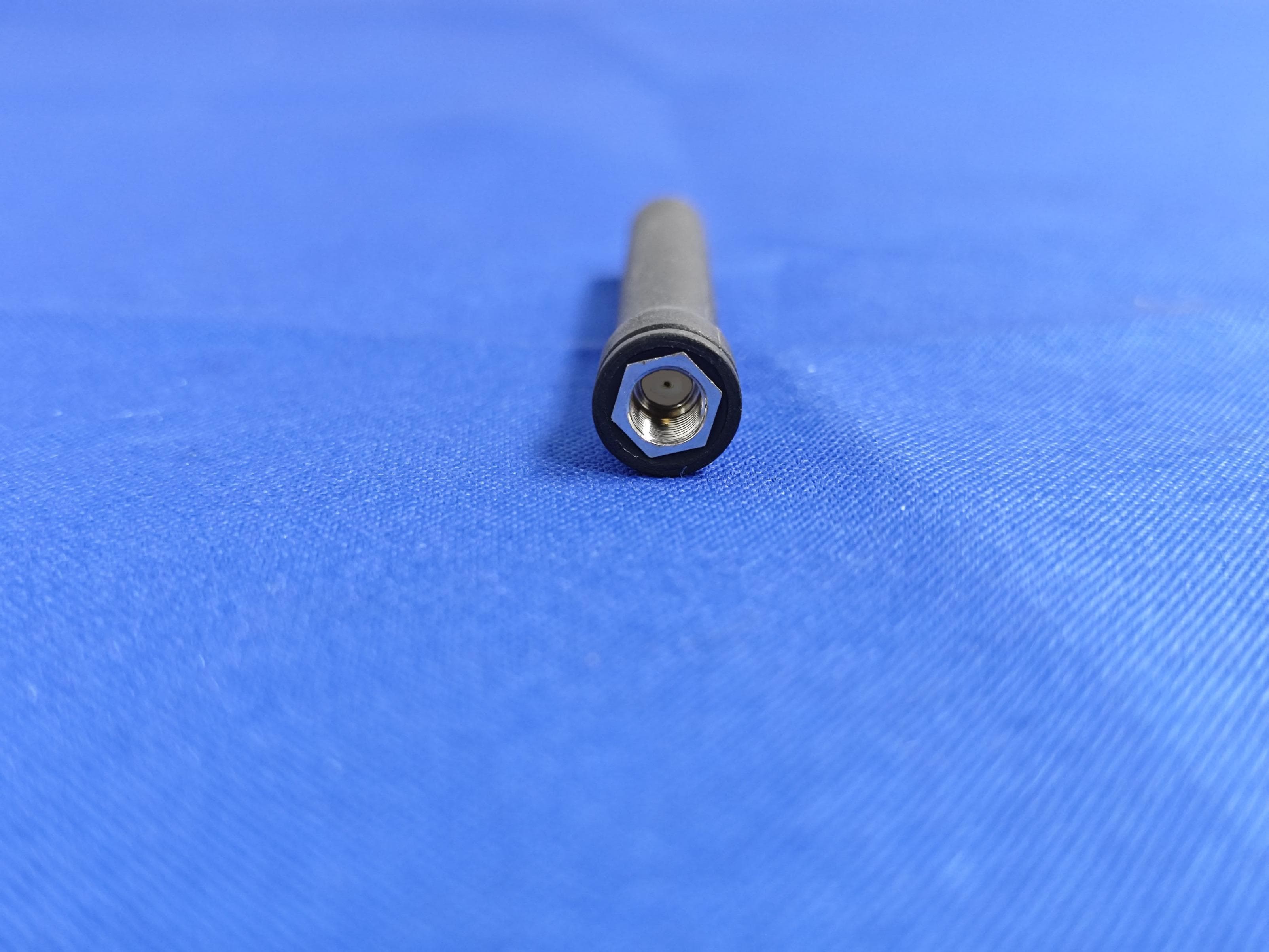
2A4FR-LS4G-4-C
Jul 09, 2023Stick Logger(4G)
Equipment Class
PCB - PCS Licensed Transmitter
2A4FRMW-4
Jul 14, 2022Module
Equipment Class
DTS - Digital Transmission System