2A5K5-MBS2Mooas Classic Dial Wireless Charging Radio Speaker
Mooas Inc.
Click to zoom
Application Details
- Equipment Class
- DSS - Part 15 Spread Spectrum Transmitter
- Date of Grant
- May 16, 2023
- Application Purpose
- Original Equipment
- Date of Application
- May 16, 2023
- Equipment Note
- Mooas Classic Dial Wireless Charging Radio Speaker
- Frequency Range
- 2402.00000000 - 2480.00000000
- Company
- Mooas Inc.
- Country
- South Korea
Documents & Files
Document Text
Text extracted from the exhibit documents filed with the FCC. Open a document above to read the original.
Users Manual
User Manual Welcome Thank you for purchasing the new Retro Wireless Speaker MBS2. Please read this manual carefully before operating your product and pay close attention to the precautions, which are mentioned below. Functions: 1, Orange LED light: When wireless charging, the LED is ON, when charging full, the LED is OFF. If error, the LED blinking. 2. Volume Knob: Turn left, decrease the volume, turn right, increase the volume. 3, Green LED light: When the FM signal is very good. 4, MODE Knob: Turn it to OFF-BT-FM-SD-AUX mode. 5, FM Knob: Turn it to the signal channel. POWER ON/OFF 1. Turn the Mode knob to any mode except OFF , the speaker is ON. 2. Turn the Mode knob to OFF mode, the speaker is OFF Bluetooth Pairing and Connecting / Disconnecting 1、 Turn the MODE knob to BT mode to power on the Bluetooth speaker. The speaker will indicate “Bluetooth”. 2、 Search for “Pairing name” on the pairing device as mobile phone and then connect. 3、 Enter password “0000” if required 4、 Turn the "Volume Knob" to adjust suitable volume. FM Radio and Manual Preset a. Turn the MODE knob to FM mode, , the speaker will indicate “FM radio”, insert an AUX antenna (included) to AUX hole. b. Slowly turn the FM knob to search for your favorite channel. When the signal is very good, the LED light will show green light. c. Turn right or turn left the "Volume Knob" to adjust suitable volume. Music playback from Micro SD /TF card a. Turn the MODE knob to SD mode, the speaker will indicate “SD Card”. b. Insert a Micro SD card. c. Turn right or turn left the "Volume Knob" to adjust suitable volume. Aux in Connection 5、 Turn the MODE knob to AUX mode, the speaker will indicate “Auxiliary”. a. b. connect the AUX cable into the aux-in port of the speaker and connect the other end into the audio-out port of your external music device. c. Turn right or turn left the "Volume Knob" to adjust suitable volume. Wireless Charging a. Before wireless charging, make sure the used phone support wireless charging. b. Plug in the Type C fast charging cable to use the PD/QCC power for charging.* c. Input : DC 5V 2A , 9V 2A Out put :5W, 7.5, 10W d. Put the phone on the speaker top section of "WIRELESS CHARGING" to charge, the orange LED light will turn on. When charge the mobile full, the orange LED light will turn off. Charging the Speaker a. Please fully charge the battery before using the device for the first time. b. Connect the 5V 2A USB cable to the unit and the other end to AC adapter or PC in order to commence charging. The Red LED will turn on indicating that the unit is now charging. Once the light goes off, this means that the units completely charged and ready to use. Product Specifications Bluetooth version: V5.1 Speaker size: 52mm RMS Power: 1 x 10W Battery: 3.7V/2200mAh lithium battery Operating Temperature Range: -10º-50º Play time: 8-10Hours (depending on 50% volume) Charging time: 2-3 hours Product Size: 168*90*90mm Weight: 520g Packing Accessories 1pc MBS2 bluetooth speaker 1pc 80cm fast charging cable 1pc 80cm Aux in cable 1pc User Manuel mooas Inc. C-819~822, Munjeong Hyundai Knowledge Industry Center, 7, Beobwon-ro 11-gil, Songpa-gu, Seoul, Korea NOTE: This equipment has been tested and found to comply with the limits for a Class B digital device, pursuant to part 15 of the FCC Rules. These limits are designed to provide reasonable protection against harmful interference in a residential installation. This equipment generates, uses and can radiate radio frequency energy and, if not installed and used in accordance with the instructions, may cause harmful interference to radio communications. However, there is no guarantee that interference will not occur in a particular installation. If this equipment does cause harmful interference to radio or television reception, which can be determined by turning the equipment off and on, the user is encouraged to try to correct the interference by one or more of the following measures: - Reorient or relocate the receiving antenna. - Increase the separation between the equipment and receiver. -Connect the equipment into an outlet on a circuit different from that to which the receiver is connected. -Consult the dealer or an experienced radio/TV technician for help. Changes or modifications not expressly approved by the party responsible for compliance could void the user's authority to operate the equipment.
Attestation Statements
Mooas Inc. C-819~822, Munjeong Hyundai Knowledge Industry Center, 7, Beobwon-ro 11-gil, Songpa-gu, Seoul 05836, Korea Federal Communications Commission Authorization and Evaluation Division 7435 Oakland Mills Road Columbia, MD 21046 USA Date: 04-28-2023 Ref: Attestation Statements Part 2.911(d)(5)(i) Filing FCC ID: 2A5K5-MBS2 [Mooas Inc.] (“the applicant”) certifies that the equipment for which authorization is sought is not “covered” equipment prohibited from receiving an equipment authorization pursuant to section 2.903 of the FCC rules. Sincerely, (Applicant signature) (Cheol woo Mun)
Attestation Statements
Mooas Inc. C-819~822, Munjeong Hyundai Knowledge Industry Center, 7, Beobwon-ro 11-gil, Songpa-gu, Seoul 05836, Korea Federal Communications Commission Authorization and Evaluation Division 7435 Oakland Mills Road Columbia, MD 21046 USA Date: 04-28-2023 Ref: Attestation Statements Part 2.911(d)(5)(ii) Filing FCC ID: 2A5K5-MBS2 [Mooas Inc.] (“the applicant”) certifies that, as of the date of the filing of the application, the applicant is not identified on the Covered List as an entity producing “covered” equipment. Sincerely, (Applicant signature) (Cheol woo Mun)
External Photos
Report No.: AGC01165230402AP02 Page 1 of 3 EXTERNAL PHOTOS TOP VIEW OF EUT BOTTOM VIEW OF EUT Report No.: AGC01165230402AP02 Page 2 of 3 FRONT VIEW OF EUT BACK VIEW OF EUT Report No.: AGC01165230402AP02 Page 3 of 3 LEFT VIEW OF EUT RIGHT VIEW OF EUT ****************************************End of Report*************************************
ID Label/Location Info
FCC ID Label Location 20mm&40mm FCC ID: 2A5K5-MBS2
Internal Photos
Report No.: AGC01165230402AP02 Page 1 of 6 INTERNAL PHOTOS OPEN VIEW OF EUT BATTERY VIEW OF EUT Report No.: AGC01165230402AP02 Page 2 of 6 INTERNAL VIEW OF EUT (FIGURE 1) INTERNAL VIEW OF EUT (FIGURE 2) FM Receive Antenna Report No.: AGC01165230402AP02 Page 3 of 6 INTERNAL VIEW OF EUT (FIGURE 3) INTERNAL VIEW OF EUT (FIGURE 4) Report No.: AGC01165230402AP02 Page 4 of 6 INTERNAL VIEW OF EUT (FIGURE 5) INTERNAL VIEW OF EUT (FIGURE 6) BT Antenna Report No.: AGC01165230402AP02 Page 5 of 6 INTERNAL VIEW OF EUT (FIGURE 7) INTERNAL VIEW OF EUT (FIGURE 8) WPT Antenna Report No.: AGC01165230402AP02 Page 6 of 6 INTERNAL VIEW OF EUT (FIGURE 9) INTERNAL VIEW OF EUT (FIGURE 10) ****************************************End of Report*************************************
RF Exposure Info
RF EXPOSURE EVALUATION 1. PRODUCT INFORMATION FCC ID 2A5K5-MBS2 Product Description Mooas Classic Dial Wireless Charging Radio Speaker Model Name MBS2 Frequency Band (Operating) WLAN: 2.412GHz ~ 2.462GHz WLAN: 5.18GHz ~ 5.32GHz / 5.50GHz ~ 5.70GHz WLAN: 5.745GHz ~ 5825GHz Bluetooth: 2.402GHz ~ 2.480GHz Others Device Category Portable (<20cm separation) Mobile (>20cm separation) Others: Antenna Diversity Single antenna Multiple antennas Max. Output Power 0.890dBm Antenna Designation PCB Antenna Antenna Gain -0.5dBi Minimum Assessment Distance 5mm Evaluation Applied MPE Evaluation SAR Evaluation Evaluation Result Pass 2. PORTABLE DEVICE EVALUATION METHOD AND LIMIT Following FCC KDB 447498 D01 “General SAR test exclusion guidance” The corresponding SAR Exclusion Threshold condition, listed below: 1) The 1-g and 10-g SAR test exclusion thresholds for 100 MHz to 6 GHz at test separation distances ≤50 mm are determined by: [(max. power of channel, including tune-up tolerance, mW)/(min. test separation distance, mm)] [if(GHz)] s 3.0 for 1-g SAR and ≤7.5 for 10-g extremity SAR, where f(GHz) is the RF channel transmit frequency in GHz. Power and distance are rounded to the nearest mW and mm before calculation. The result is rounded to one decimal place for comparison The test exclusions are applicable only when the minimum test separation distance is ≤50 mm and for transmission frequencies between 100 MHz and 6 GHz. When the minimum test separation distance is < 5 mm, a distance of 5 mm is applied to determine SAR test exclusion. 2) At 100 MHz to 6 GHz and for test separation distances > 50 mm, the SAR test exclusion threshold is determined according to the following: a) [Threshold at 50 mm in step 1) + (test separation distance - 50mm) ( f(MHz)/150)] mW, at 100MHz to 1500 MHz; b) [Threshold at 50 mm in step 1) + (test separation distance - 50 mm)-10] mW at > 1500 MHz and ≤6 GHz; 3) At frequencies below 100 MHz, the following may be considered for SAR test exclusion. a) The threshold at the corresponding test separation distance at 100 MHz in step 2) is multiplied by [1 + log(100/f(MHz))] for test separation distances > 50 mm and < 200 mm. b) The threshold determined by the equation in a) for 50 mm and 100 MHz is multiplied by 1/2 for test separation distances ≤50 mm. c) SAR measurement procedures are not established below 100 MHz. When SAR test exclusion cannot be applied, a KDB inquiry is required to determine SAR evaluation requirements for any test results to be acceptable. 3. MOBILE DEVICE EVALUATION METHOD AND LIMIT Human exposure to RF emissions from mobile devices (47 CFR §2.1091) may be evaluated based on the MPE limits adopted by the FCC for electric and magnetic field strength and/or power density, as appropriate, since exposures are assumed to occur at distances of 20 cm or more from persons. LIMITS FOR GENERAL POPULATION / UNCONTROLLED EXPOSURE Frequency Range (MHz) E-field Strength (E) (V/m) Magnetic Field Strength (H) (A/m) Power Density (S) (mW/cm 2 ) Averaging Time |E| 2 , |H| 2 or S (Minutes) 0.3 -- 1.34 614 1.63 (100)* 30 1.34 -- 30 824/f 2.19/f (180/f 2 )* 30 30 -- 300 27.5 0.073 0.2 30 300 -- 1500 -- -- f/1500 30 1500 -- 100,000 -- -- 1.0 30 *Note: 1. f= Frequency in MHz * Plane-wave Equivalent Power Density 2. The averaging time for General Population/Uncontrolled exposure to fixed transmitters is not applicable for mobile and portable transmitters. See 47 CFR §§2.1091 and 2.1093 on source-based time-averaging requirement for mobile and portable transmitters. S=PG/4πR² Where: S=power density P=power input to antenna G=power gain of the antenna in the direction of interest relative to an isotropic radiator R=distance to the center of radiation of the antenna 4. MEASUREMENT RESULT Test Mode Channel Frequency (MHz) Max Output power (dBm) Max Output power (mW) Calculati on Value (Note 1) Threshold Value 8DPSK BT_BDR 2402 0.830 1.211 0.375 3.0 BT_BDR 2441 0.890 1.227 0.383 3.0 BT_BDR 2480 0.613 1.152 0.362 3.0 Note 1: Calculation Value =[(max. power of channel, mW)/(min. test separation distance, mm)] ·[√f(GHz)]. Fox example: 1.227/5*√2.441=0.383 ≤ 3.0 According to KDB447498 D01 V06, threshold at which no SAR required is ≤3.0 for 1-g SAR, separation distance is 5mm, and no simultaneous SAR measurement is required. 5. CONCLUSION Since Source-base time average power is below SAR test exclusion power thresholds, the SAR evaluation is not required.
Test Report
InvertedFAntennaSpecification Summary ITEMANTSPEC ModelName2.4GANT Center Frequency HorizontalVertical 2400MHz2400MHz2500MHz2400MHz2400MHz2500MHz -1.26-0.76-0.5-5.25-2.46-1.86 MAX.Gain-0.5dBi PolarizationHorizontalandVertical AzimuthBeam Pattern Omni-directional Impedance50Ohm Antenna Length 38.20mm ManufactureZHUHAIJIELITECHNOLOGYCO.,LTD AntennaPhoto&Length(mm) Horizontal:2400MHz2450MHz2500MHz Power(dBi) Max:0Min:-40Scale:5/div Frequency (MHz) Gain(dBi) MaxMinAvg 2400-1.26174-30.0801-7.18716 2450-0.765802-36.5604-7.48023 2500-0.50-22.0315-6.59127 Vertical:2400MHz2450MHz2500MHz Power(dBi) Max:0Min:-30Scale:5/div Frequency (MHz) Gain(dBi) MaxMinAvg 2400-5.2537-22.1424-12.4294 2450-2.4652-24.5837-10.4702 2500-1.86120-29.5214-9.20432
Test Report
Page 1 of 69 FCC Test Report Report No.: AGC01165230402FE03 FCC ID : 2A5K5-MBS2 APPLICATION PURPOSE : Original Equipment PRODUCT DESIGNATION : Mooas Classic Dial Wireless Charging Radio Speaker BRAND NAME : N/A MODEL NAME : MBS2 APPLICANT : mooas Inc. DATE OF ISSUE : Apr. 26, 2023 STANDARD(S) : FCC Part 15.247 REPORT VERSION : V1.0 Attestation of Global Compliance (Shenzhen) Co., Ltd Report No.: AGC01165230402FE03 Page 2 of 69 REPORT REVISE RECORD Report Version Revise Time Issued Date Valid Version Notes V1.0 / Apr. 26, 2023 Valid Initial Release Report No.: AGC01165230402FE03 Page 3 of 69 TABLE OF CONTENTS 1. VERIFICATION OF CONFORMITY .................................................................................................................. 5 2. GENERAL INFORMATION .............................................................................................................................. 6 2.1. PRODUCT DESCRIPTION ........................................................................................................................ 6 2.2. TABLE OF CARRIER FREQUENCYS ....................................................................................................... 6 2.3. RECEIVER INPUT BANDWIDTH .............................................................................................................. 7 2.4. EXAMPLE OF A HOPPING SEQUENCY IN DATA MODE ......................................................................... 7 2.5. EQUALLY AVERAGE USE OF FREQUENCIES AND BEHAVIOUR ......................................................... 7 2.6. RELATED SUBMITTAL(S) / GRANT (S) .................................................................................................... 8 2.7. TEST METHODOLOGY ............................................................................................................................. 8 2.8. SPECIAL ACCESSORIES ......................................................................................................................... 8 2.9. EQUIPMENT MODIFICATIONS ................................................................................................................. 8 2.10. ANTENNA REQUIREMENT..................................................................................................................... 8 3. MEASUREMENT UNCERTAINTY ................................................................................................................... 9 4. DESCRIPTION OF TEST MODES ................................................................................................................. 10 5. SYSTEM TEST CONFIGURATION ................................................................................................................. 11 5.1. CONFIGURATION OF EUT SYSTEM ....................................................................................................... 11 5.2. EQUIPMENT USED IN TESTED SYSTEM ............................................................................................... 11 5.3. SUMMARY OF TEST RESULTS ............................................................................................................... 11 6. TEST FACILITY .............................................................................................................................................. 12 7. PEAK OUTPUT POWER ................................................................................................................................ 13 7.1. MEASUREMENT PROCEDURE ............................................................................................................. 13 7.2. TEST SET-UP (BLOCK DIAGRAM OF CONFIGURATION) .................................................................... 13 7.3. LIMITS AND MEASUREMENT RESULT .................................................................................................. 14 8. 20DB BANDWIDTH ........................................................................................................................................ 19 8.1. MEASUREMENT PROCEDURE ............................................................................................................. 19 8.2. TEST SET-UP (BLOCK DIAGRAM OF CONFIGURATION) .................................................................... 19 8.3. LIMITS AND MEASUREMENT RESULTS ............................................................................................... 20 9. CONDUCTED SPURIOUS EMISSION........................................................................................................... 25 9.1. MEASUREMENT PROCEDURE ............................................................................................................. 25 9.2. TEST SET-UP (BLOCK DIAGRAM OF CONFIGURATION) .................................................................... 25 9.3. MEASUREMENT EQUIPMENT USED .................................................................................................... 25 9.4. LIMITS AND MEASUREMENT RESULT .................................................................................................. 25 10. RADIATED EMISSION ................................................................................................................................. 46 Report No.: AGC01165230402FE03 Page 4 of 69 10.1. MEASUREMENT PROCEDURE ........................................................................................................... 46 10.2. TEST SETUP ......................................................................................................................................... 48 10.3. LIMITS AND MEASUREMENT RESULT ............................................................................................... 49 10.4. TEST RESULT........................................................................................................................................ 49 11. NUMBER OF HOPPING FREQUENCY ................................................................…
Text truncated - open the document above for the full version.
Test Report
Report No.: AGC01165230402FE03 Page 59 of 69 11. NUMBER OF HOPPING FREQUENCY 11.1. MEASUREMENT PROCEDURE The EUT shall have its hopping function enabled. Use the following spectrum analyzer settings: 1. Span: The frequency band of operation. Depending on the number of channels the device supports, it may be necessary to divide the frequency range of operation across multiple spans, to allow the individual channels to be clearly seen. 2. RBW: To identify clearly the individual channels, set the RBW to less than 30% of the channel spacing or the 20 dB bandwidth, whichever is smaller. 3. VBW ≥ RBW. Sweep: Auto. Detector function: Peak. Trace: Max hold. 4. Allow the trace to stabilize. 11.2. TEST SETUP (BLOCK DIAGRAM OF CONFIGURATION) Same as described in section 8.2 11.3. MEASUREMENT EQUIPMENT USED The same as described in section 6 11.4. LIMITS AND MEASUREMENT RESULT Test Data of Number of Hopping Frequency Test Mode Number of Hopping Frequency Limits Pass or Fail GFSK Hopping 79 >=15 Pass Test Graphs of Number of Hopping Frequency Test_Graph_BR_HOP_ANT1_NA_1Mbps_Number of Hopping Note: The GFSK modulation is the worst case and recorded in the report. Report No.: AGC01165230402FE03 Page 60 of 69 12. TIME OF OCCUPANCY (DWELL TIME) 12.1. MEASUREMENT PROCEDURE The EUT shall have its hopping function enabled. Use the following spectrum analyzer settings: 1. Span: Zero span, centered on a hopping channel. 2. RBW shall be≤channel spacing and where possible RBW should be set >> 1 / T, where T is the expected dwell time per channel. 3. Sweep: As necessary to capture the entire dwell time per hopping channel; where possible use a video trigger and trigger delay so that the transmitted signal starts a little to the right of the start of the plot. The trigger level might need slight adjustment to prevent triggering when the system hops on an adjacent channel; a second plot might be needed with a longer sweep time to show two successive hops on a channel. 4. Detector function: Peak. Trace: Max hold. 5. Use the marker-delta function to determine the transmit time per hop. 6. Repeat the measurement using a longer sweep time to determine the number of hops over the period specified in the requirements. The sweep time shall be equal to, or less than, the period specified in the requirements. Determine the number of hops over the sweep time and calculate the total number of hops in the period specified in the requirements, using the following equation: (Number of hops in the period specified in the requirements) = (number of hops on spectrum analyzer) × (period specified in the requirements / analyzer sweep time). 7. The average time of occupancy is calculated from the transmit time per hop multiplied by the number of hops in the period specified in the requirements. 12.2. TEST SETUP (BLOCK DIAGRAM OF CONFIGURATION) Same as described in section 8.2 12.3. MEASUREMENT EQUIPMENT USED The same as described in section 6 12.4. LIMITS AND MEASUREMENT RESULT Test Data of Dwell Time Channel Time of Pulse for DH5 (ms) Number of hops in the period specified in the requirements Sweep Time (ms) Limit (ms) Pass or Fail 2402 2.879 25.0*4 287.900 400 Pass 2441 2.879 25.0*4 287.900 400 Pass 2480 2.879 30.0*4 345.480 400 Pass Note: The GFSK modulation is the worst case and recorded in the report. Report No.: AGC01165230402FE03 Page 61 of 69 Test Graphs of Dwell Time Test_Graph_BR_HOP_ANT1_NA_1Mbps_2402_Number of Busrt Test_Graph_BR_HOP_ANT1_NA_1Mbps_2402_Time per Burst Report No.: AGC01165230402FE03 Page 62 of 69 Test_Graph_BR_HOP_ANT1_NA_1Mbps_2441_Number of Busrt Test_Graph_BR_HOP_ANT1_NA_1Mbps_2441_Time per Burst Report No.: AGC01165230402FE03 Page 63 of 69 Test_Graph_BR_HOP_ANT1_NA_1Mbps_2480_Number of Busrt Test_Graph_BR_HOP_ANT1_NA_1Mbps_2480_Time per Burst Report No.: AGC01165230402FE03 Page 64 of 69 13. FREQUENCY SEPARATION 13.1. MEASUREMENT PROCEDURE The EUT shall have its hopping function enabled. Use the following spectrum analyzer settings: 1. Span: Wide enough to capture the peaks of two adjacent channels. 2. RBW: Start with the RBW set to approximately 30% of the channel spacing; adjust as necessary to best identify the center of each individual channel. 3. Video (or average) bandwidth (VBW) ≥ RBW. 4. Sweep: Auto. e) Detector function: Peak. f) Trace: Max hold. g) Allow the trace to stabilize. Use the marker-delta function to determine the separation between the peaks of the adjacent channels. 13.2. TEST SETUP (BLOCK DIAGRAM OF CONFIGURATION) Same as described in section 6.2 13.3. MEASUREMENT EQUIPMENT USED The same as described in section 6.3 13.4. LIMITS AND MEASUREMENT RESULT Test Data of Frequency Separation Test Mode Channel Separation (MHz) Limits Pass or Fail GFSK Hopping 0.997 >= 2/3 -20dB BW Pass Test Graphs of Number of Hopping Frequency Test_Graph_BR_HOP_ANT1_NA_1Mbps_Hopping Separation Note: The GFSK modulation is the worst case and recorded in the report. Report No.: AGC01165230402FE03 Page 65 of 69 14. LINE CONDUCTED EMISSION TEST 14.1. LIMITS OF LINE CONDUCTED EMISSION TEST Frequency Maximum RF Line Voltage Q.P. (dBμV) Average (dBμV) 150kHz~500kHz 66-56 56-46 500kHz~5MHz 56 46 5MHz~30MHz 60 50 Note: 1. The lower limit shall apply at the transition frequency. 2. The limit decreases linearly with the logarithm of the frequency in the range 0.15 MHz to 0.50 MHz. 14.2. BLOCK DIAGRAM OF LINE CONDUCTED EMISSION TEST EUT & Support Units Report No.: AGC01165230402FE03 Page 66 of 69 14.3. PRELIMINARY PROCEDURE OF LINE CONDUCTED EMISSION TEST 1. The equipment was set up as per the test configuration to simulate typical actual usage per the user’s manual. When the EUT is a tabletop system, a wooden table with a height of 0.8 meters is used and is placed on the ground plane as per ANSI C63.10 (see Test Facility for the dimensions of the ground plane used). When the EUT is a floor-standing equipment, it is placed on the ground plane which has a 3-12 mm non-conductive covering to insulate the EUT from the gro…
Text truncated - open the document above for the full version.
Test Setup Photos
Report No.: AGC01165230402AP01 Page 1 of 7 TEST SETUP PHOTOS RADIATED EMISSION TEST SETUP BELOW 30MHz (WPT) RADIATED EMISSION TEST SETUP BELOW 1GHz (WPT) Report No.: AGC01165230402AP01 Page 2 of 7 RADIATED EMISSION TEST SETUP BELOW 1GHz (BT) RADIATED EMISSION TEST SETUP ABOVE 1GHz (BT) Report No.: AGC01165230402AP01 Page 3 of 7 AC POWER LINE CONDUCTED TEST SETUP (WPT) AC POWER LINE CONDUCTED TEST SETUP (BT) Report No.: AGC01165230402AP01 Page 4 of 7 RF CONDUCTED TES SETUP Report No.: AGC01165230402AP01 Page 5 of 7 RF HEALTH ASSESSMENT TEST PHOTOS H-Field & E-Field Strength_ Position A H-Field & E-Field Strength_ Position B Report No.: AGC01165230402AP01 Page 6 of 7 H-Field & E-Field Strength_ Position C H-Field & E-Field Strength_ Position D Report No.: AGC01165230402AP01 Page 7 of 7 H-Field & E-Field Strength_ Position E ****************************************End of Report*************************************
Contact Information
Applicant
Cheol woo Mun(CEO)
Technical Contact
Test Firm
Attestation of Global Compliance (Shenzhen) Co., LDoris Li
[email protected]+86-755-25234088
Technical Specifications
| # | Rule Parts | Frequency Range | Power Output |
|---|---|---|---|
| 1 | 15C | 2.40 GHz - 2.48 GHz | 1.20 mW |
Other Applications from Mooas Inc.
2A5K5-MWCS3R
Sep 05, 2024WIRELESS CHARGER
Equipment Class
DCD - Part 15 Low Power Transmitter Below 1705 kHz
2A5K5-MWCS3S1R
Sep 05, 2024WIRELESS CHARGER
Equipment Class
DCD - Part 15 Low Power Transmitter Below 1705 kHz
2A5K5-MWCS9
Jul 07, 2024Flip Square 3-in-1 High-Speed wireless charging Mood Lamp
Equipment Class
DCD - Part 15 Low Power Transmitter Below 1705 kHz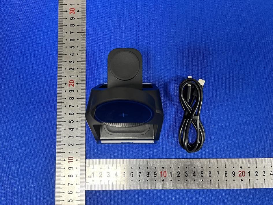
2A5K5-MWCS7S1
Jun 19, 2024Mooas Crystal Lamp 3 in1 Magsafe Stand
Equipment Class
DCD - Part 15 Low Power Transmitter Below 1705 kHz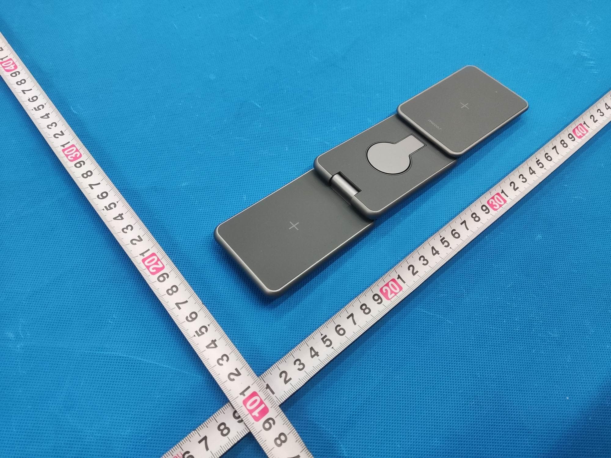
2A5K5-MWCS5
Mar 12, 202415W Foldable 3IN1 magsafe wireless charge
Equipment Class
DCD - Part 15 Low Power Transmitter Below 1705 kHz