2A9YKCWRTWSCENEWHPure Smart Remote Room Controller
Pure Edge Lighting LLC.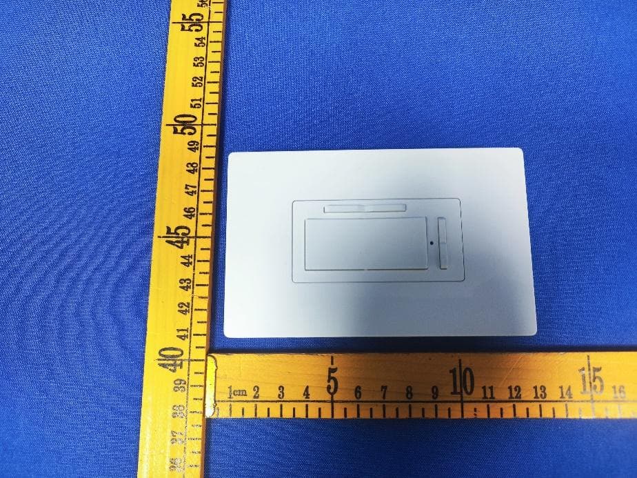
Click to zoom
Application Details
- Equipment Class
- DTS - Digital Transmission System
- Date of Grant
- Mar 08, 2024
- Application Purpose
- Original Equipment
- Date of Application
- Mar 08, 2024
- Equipment Note
- Pure Smart Remote Room Controller
- Frequency Range
- 2412.00000000 - 2462.00000000
- Company
- Pure Edge Lighting LLC.
- Country
- United States
Documents & Files
Document Text
Text extracted from the exhibit documents filed with the FCC. Open a document above to read the original.
Users Manual
Contents • Download the app • How to Commission the Controller • Device Components • Methods for Mounting • Device Button Schematic • Notes Before Installation Section 1. Overview Section 2. Installation For more details, please refer to the manual. If you have any questions during installation, please contact us [email protected] Section 3. App Pairing ImportantNote:Tocomplywith the FCC RF exposurecompliance requirements,nochange tothe antenna or the device ispermitted. Any change tothe antenna or thedevicecouldresultin the device exceeding the RFexposurerequirements and voiduser’s authorityto operate the device. ImportantNotice: Battery Compatibility: Ensurethat you use batteries that arecompatiblewith theproduct's specifications as outlined intheuserma nual.Using incompatiblebatteries may damage theproductorposesafetyrisks. Battery Installation: Followtheusermanualinstructions for proper batteryinstallation. Incorrect installation mayleadtoproduct malfunction, damage,or potential hazards. Battery Safety: Always exercisecautionwhen handling andusing batteries. Keep them awayfromchildren and pets.Donotexposebatteries toextreme temperatures, direct sunlight,ormoisture, as itmaylead to leakage, overheating, or other safetyissues. Liability: Themanufacturer isnotresponsible for any damage t otheproduct or anythird-partyproperty or personalinjuriescaused bythe use ofbatteries, includingbutnotlimitedto leakage,overheating, or malfunction. By purchasing andusing thisproduct, you acknowledge and acceptthesebattery-related risks andrelease themanufacturer from anyliabilityrelated to theinstallation, use,orconsequences of the batteries in this product. Please readtheproductuser manual andfollow allsafety guidelinesprovidedto ensurethesafeand properoperationof thisproduct. Alwaysseekprofessional advicefor battery-related concerns, and dispose of used b atteries in accordance withlocalregulations. Remember,it's crucial to consultwith a legal professionaltoensureyourdisclaimer is legallysound and suitablefor your specific product andjurisdiction. Pantone 2995C/CP SIZE: 420 x 297 mm 80G 105 x 74.25 mm Drywall Anchors x2 6-32 Screws x2 #6 Screws x2 Room Controller x1 Pure Smart Remote Room Controller Wi-Fi Enabled - Connected by WiZ Pro - Battery Powered Totally Wireless Single Pole or 3-Way Installation Model #: Wiz34,CWR-TW-SCENE-WH Specifications:Included in Box: If you have any questions, please contact us at [email protected] Power: 3VDC Battery Powered, 60Hz 4 AAA Batteries (not included) Wireless Frequency: 2.4GHz Wireless Standard: IEEE802.11b/g/n No load maximum Temperature Range: 32° F~104° F Wi-Fi Access point Rated for Indoor use only For control of WiZ smart loads only Notes before installation 1) Since the Pure Smart Remote Room Controller is a completely wireless, battery powered, device, there is no limit to the number of devices that can be connected to the it. Neutral wire is NOT REQUIRED for installation. 2) Works with WiZ Connected smart lamps or fixtures only. Not for use with non-smart bulbs or fixtures. Compatible with any WiZ Connected or Pure Smart lamp/fixture/device. 3) Works only with another Pure Smart or WiZ Connected wall control for multi-location control. Only compatible with CWW-TW-SCENE-WH, CWR-TW-SCENE-WH, SWW-SWT-WH, and SWW-DIM-WH 4) The remote room controller can be installed on an existing junction box, anchored/screwed into drywall, or adhered to a tabletop or any surface with the two sided adhesive (included). All materials needed for installation are included with the product. Directions for each installation method are included in Section 2. Two Sided Adheasive Pads x2 Neoprene Pads x2 Section 2. Mounting the Device FOR MULTI-LOCATION CONTROL: For multi-location control with the Pure Smart Room Controller and Pure Smart Wi-Fi Switch or Dimmer, you’ll place the Room Controller in the same room and make the Smart Switch or Dimmer the target for the Room Controller. For multi-location control with 2 Room Controllers, you’ll place both of them in the same room, allowing for both controllers to have full control over every fixture in the room, or you'll select the same target(s) for both Room Controllers. Targets refer to any device/lamp/fix- ture that the Room Controller is in control of in the WiZ App. Junction Box Installation Drywall Installation Surface Installation Section 3. App Pairing Smart Pairing Additional Settings for Wall Controller Accessory 6 6 When you receive the “Accessory found” message you may press done and begin controlling the light fixtures in that room with your Wall Controller. Follow additional instructions below to personalize settings and controls. Follow the on-screen instructions and ensure that your Wall Controller is connected to 120V power and then press “START”. 4 2 Select “Wall Controller” from the available device types. 1 5 Follow the on-screen instructions by pressing the On button 3 times and wait while the WiZ app looks for your Wall Controller. Select whichever room the Wall Controller will be installed in or controlling. 3 Once your lamps or fixtures have been connected, press the plus sign in the top right hand corner to add your smart room controller. Or you can choose an entire room for the Wall Controller to control. If needed, you have the option to rename your Wall Controller. 4 2 Select “Accessories” from the Settings menu. 1 5 You can select individual targets that the Wall Controller will control by choosing specific fixtures or devices. Select the Wall Controller that you’d like to customize control with. 3 For additional setup, select “Settings” on the bottom right hand corner of the Home screen. For WiZ Pro Dashboard Users: WiZ Pro Dashboard account and home must be created before starting commissioning in the WiZ app. Please create an account on WiZ Pro Dashboard. Then create your "settings" and then the "members" tab. By clicking on the "Invite" button you will be able to gen…
Text truncated - open the document above for the full version.
Attestation Statements
PureEdgeLightingLLC. 1718W.FullertonAveChicagoIllinois,60614,UnitedStates FederalCommunicationsCommission AuthorizationandEvaluationDivision EquipmentAuthorizationBranch 7435OaklandMillsRoad Columbia,MD21046 {Jan.29,2024} U.S.AgentDesignation {PureEdgeLightingLLC.}acknowledgestheirconsentforthefollowingcontactlocatedintheUnitedStatesto actastheiragentforserviceofprocessfortheequipmentforwhichauthorizationissought (FCCID:2A9YKCWRTWSCENEWH): NameandcompanyofU.S.agent: PureEdgeLightingLLC. PhysicalU.S.addressofagent: 1718W.FullertonAveChicagoIllinois,60614,UnitedStates FRNofU.S.agent:0032171019 EmailaddressofU.S.agent:[email protected] {PureEdgeLightingLLC.}acknowledgestheirobligationtoacceptserviceofprocessonbehalfof{PureEdge LightingLLC.}. {PureEdgeLightingLLC.}withtheFRN[0032171019]acceptsitsobligationtomaintainanagentforserviceof processintheUnitedStatesfornolessthan3yearaftereitherthegranteehaspermanentlyterminatedall marketingandimportationoftheapplicableequipmentwithintheU.S.,ortheconclusionofanyCommission- relatedadministrativeorjudicialproceedinginvolvingtheequipment,whicheverislater. Bysigningthisform,weconfirmtheaboveandthatweareawareoftheapplicationrequirementslistedunder§ 2.911(d)(7). TheinformationprovidedinthisletterisbasedonthereferencedrulepartsofTitle47oftheCFRaswellasKDB 986446D01. Anexpirationdateforthisletterdoesnotexist.IncasetheU.S.agentchanges,thegranteeisobligatedtonotify theFCCwithin30daysviathegrantingTCB. Sincerely, Signature {BlakeMatthew} {NationalSalesManager-SmartTechnology} {PureEdgeLightingLLC.} Signature {BlakeMatthew} {NationalSalesManager-SmartTechnology} {PureEdgeLightingLLC.} 4 8 _ [ m o d e l ] U S _ A g e n t _ 2 . 9 1 1 ( d ) ( 7 ) - U , V 0 5
External Photos
FCCID:2A9YKCWRTWSCENEWH FCCID:2A9YKCWRTWSCENEWH FCCID:2A9YKCWRTWSCENEWH
ID Label/Location Info
1/1
Internal Photos
FCCID:2A9YKCWRTWSCENEWH FCCID:2A9YKCWRTWSCENEWH FCCID:2A9YKCWRTWSCENEWH FCCID:2A9YKCWRTWSCENEWH FCCID:2A9YKCWRTWSCENEWH
RF Exposure Info
ReportNo.:PTC24010214001E-FC02 Page1of7 FCCTESTREPORT FCCID:2A9YKCWRTWSCENEWH Product:PureSmartRemoteRoomController ModelName:Wiz34,CWR-TW-SCENE-WH Brand:N/A ReportNo.:PTC24010214001E-FC02 Preparedfor PureEdgeLightingLLC. 1718W.FullertonAveChicagoIllinois,60614,UnitedStates Preparedby PreciseTesting&CertificationCo.,Ltd. Building1,No.6,TongxinRoad,DongchengStreet,Dongguan,Guangdong,China. ReportNo.:PTC24010214001E-FC02 Page2of7 TESTRESULTCERTIFICATION Applicant’sname:PureEdgeLightingLLC. Address:1718W.FullertonAveChicagoIllinois,60614,UnitedStates Manufacture'sname: NIE-TECHCo.,Ltd Address: Jiliancommercialcenter9001,JinxiuroadNo.2,Changan Town,DongguanCity,GuangDongProv.,CHINA Productname: PureSmartRemoteRoomController Modelname: Wiz34,CWR-TW-SCENE-WH,CWR-TW-SCENE-WH Testprocedure:FCCCFR47Part1.1307(b)(1) TestDate:Jan.05,2024toJan.22,2024 DateofIssue:Jan.29,2024 TestResult:PASS ThisdevicedescribedabovehasbeentestedbyPTC,andthetestresultsshowthatthe equipmentundertest(EUT)isincompliancewiththeFCCrequirements.Anditisapplicable onlytothetestedsampleidentifiedinthereport. Thisreportshallnotbereproducedexceptinfull,withoutthewrittenapprovalofPTC,this documentmaybealteredorrevisedbyPTC,personalonly,andshallbenotedinthe revisionofthedocument. TestEngineer: Jackzhou/Engineer TechnicalManager: SimonPu/Manager ReportNo.:PTC24010214001E-FC02 Page3of7 Contents Page 2TESTSUMMARY...............................................................................................................................................4 3GENERALINFORMATION..............................................................................................................................5 3.1GENERALDESCRIPTIONOFE.U.T..........................................................................................................5 4RFEXPOSURE..................................................................................................................................................6 4.1REQUIREMENTS........................................................................................................................................6 4.2THEPROCEDURES/LIMIT........................................................................................................................6 4.3MPECALCULATIONMETHOD..................................................................................................................7 4.4TESTRESULT...........................................................................................................................................7 ReportNo.:PTC24010214001E-FC02 Page4of7 2TestSummary TestItemsTestRequirementResult MaximumPermissibleExposure (ExposureofHumanstoRFFields) 15.247(i)PASS Remark: N/A:NotApplicable ReportNo.:PTC24010214001E-FC02 Page5of7 3GeneralInformation 3.1GeneralDescriptionofE.U.T. ProductName : PureSmartRemoteRoomController ModelName : Wiz34 Additionalmodel : CWR-TW-SCENE-WH Modeldifference:Differentmodelnames Specification : 802.11b/g/nHT20 OperationFrequency : 2412-2462MHzfor802.11b/g/n(HT20 NumberofChannel : 11channelsfor802.11b/g/n(HT20) TypeofModulation : DSSSwithDBPSK/DQPSK/CCKfor802.11b; OFDMwithBPSK/QPSK/16QAM/64QAMfor802.11g/n; Antennainstallation : PCBantenna AntennaGain : 2.72dBi Powersupply : DC3V HardwareVersion : N/A SoftwareVersion : N/A ReportNo.:PTC24010214001E-FC02 Page6of7 4RFExposure TestRequirement :FCCPart1.1307(b)(1) EvaluationMethod :KDB447498D01GeneralRFExposureGuidancev06 4.1Requirements Systemsoperatingundertheprovisionsofthissectionshallbeoperatedinamannerthatensuresthat thepublicisnotexposedtoradiofrequencyenergylevelsinexcesslimitformaximumpermissible exposure.Inaccordancewith47CFRFCCPart2SubpartJ,section2.1091thisdevicehasbeen definedasamobiledevicewherebyadistanceof0.2mnormallycanbemaintainedbetweentheuser andthedevice. 4.2Theprocedures/limit (A)LimitsforOccupational/ControlledExposure FrequencyRangeElectricFieldMagneticFieldPowerDensity(S)AveragingTime 0.3-3.06141.63(100)*6 3.0-301842/f4.89/f(900/f)*6 30-30061.40.1631.06 300-1500F/3006 1500-100,00056 (B)LimitsforGeneralPopulation/UncontrolledExposure FrequencyRangeElectricFieldMagneticFieldPowerDensity(S)AveragingTime 0.3-1.346141.63(100)*30 1.34-30824/f2.19/f(180/f)*30 30-30027.50.0730.230 300-1500F/150030 1500-100,0001.030 Note:f=frequencyinMHz;*Plane-waveequivalentpowerdensity ReportNo.:PTC24010214001E-FC02 Page7of7 4.3MPECalculationMethod E(V/m)= d GP30 PowerDensity:Pd(W/m²)= 377 2 E E=Electricfield(V/m) P = PeakRFoutputpower(W) G=EUTAntennanumericgain(numeric) d = Separationdistancebetweenradiatorandhumanbody(m) Theformulacanbechangedto Pd= 2 377 30 d GP θφ FromthepeakEUTRFoutputpower,theminimummobileseparationdistance,d=0.2m,aswellas thegainoftheusedantenna,theRFpowerdensitycanbeobtained 4.4TestResult Mode Antenna Gain (numeric) Max.Peak OutputPower (dBm) Tuneup tolerance (dBm) MaxTuneUp Power(mW) PowerDensity (mW/cm2) LimitofPower Density (mW/cm2) Result 24621.8716.2216.22±152.7229860.0196211Pass ******THEENDREPORT******
Test Report
ReportNo.:RFI-LAB-RF-202306-FF14-1 QP030-E41 Page1of10 TestingReport CustomerName:NIE-TECHCo.,Ltd ProductName:ESP-WROOM-02D-ANT SampleModel:ESP-WROOM-02D-ANT ReferenceStandard:GB/T9410-2008;ANSI/IEEEStd149-1979 IssueDate:2023.6.14 Engineer:Date: Auditor:Date: Approver:Date: ReportNo.:RFI-LAB-RF-202306-FF14-1 QP030-E41 Page2of10 Version VersionNo.DateDescriptionFormulateApproval A02023.6.14Forthefirsttime,formulateZkrisEason Contents 1.GeneralInformation.........................................................................................................................3 1.1Generalinformationoftestinginstitutions...........................................................................3 1.2Testingprinciple...................................................................................................................3 1.3Testequipment......................................................................................................................4 1.4Testenvironment...................................................................................................................4 1.5Statement..............................................................................................................................4 2.SampleInformation.........................................................................................................................5 2.1Clientinformation.................................................................................................................5 2.2DescriptionofEUT(S)..........................................................................................................5 2.3EUTappearance....................................................................................................................6 2.4EUTsetupphotooffreespaceOTAtesting.........................................................................6 3.TestResults.....................................................................................................................................7 3.1Teststandard.........................................................................................................................7 3.2Testuncertainty.....................................................................................................................7 3.3Testdata................................................................................................................................8 3.3.1VSWRparameters.....................................................................................................8 3.3.2VSWRdata................................................................................................................8 3.3.3Typicalfreespaceefficiencyandgain......................................................................8 3.3.4Typicalfreespaceradiationpattern...........................................................................9 (Thefollowingisblank)..............................................................................................................10 ReportNo.:RFI-LAB-RF-202306-FF14-1 QP030-E41 Page3of10 1.GeneralInformation 1.1Generalinformationoftestinginstitutions Name ShenzhenRFI-LABCommunicationTechnologyCo.,Ltd. Address 10/FA,LingyunBld,LiufangRd,BaoanDistrict,SZ Tel 13682621346 E-mail [email protected] Equipment AlltheequipmentusedinthereportisfixedinZoneB,WestSideof1/F,Building1, TingweiIndustrialPark,No.6LiufangRoad,Bao'anDistrict,Shenzhen 1.2Testingprinciple ReportNo.:RFI-LAB-RF-202306-FF14-1 QP030-E41 Page4of10 1.3Testequipment EquipmentModelNo.SerialNo.Manufacturer Calibration date Next calibration date OTATest System RayZone-5000 RFI-LAB-RF -D00 GTS2023.3.142025.3.13 Network Analyzer E5071C RFI-LAB-RF -D01 KEYSIGHT2023.5.112024.5.10 Network Analyzer E5071C RFI-LAB-RF -C02 KEYSIGHT2023.5.112024.5.10 1.4Testenvironment Temperature 24.2°C Humidity 59%RH Pressure 100.15kPa 1.5Statement (1)Thetestresultsinthereportareonlyapplicabletothetestedsamplesandthetestedsamples workundertheenvironmentdescribedinthereport. (2)OnlyShenzhenRFI-LABCommunicationTechnologyCo.,Ltd.havetherighttomodifythe report,andthemodificationinformationshallbeannotatedintherevisionform. (3)Anyobjectiontothisreportshallberaisedwithin30daysafterformalconfirmationofthe report. (4)Thisreportisinvalidifthereisanyevidencethatthesampleinformationprovidedisfalsified. (5)Thereportisinvalidwithoutthesignatureoftheauditorandapprover. ReportNo.:RFI-LAB-RF-202306-FF14-1 QP030-E41 Page5of10 2.SampleInformation 2.1Clientinformation Name NIE-TECHCo.,Ltd Address / Contacts / Tel / E-mail / Manufacturer / 2.2DescriptionofEUT(S) ProductName ESP-WROOM-02D-ANT SampleModel ESP-WROOM-02D-ANT AntennaSize / SerialNo. / AntennaType PCBAntenna TestItem VSWR;Antennagain;Efficiency;Radiationpattern FrequencyRange 2400-2500MHz ReceivedDate 2023.6.12 TestDate 2023.6.13 Remark ThelengthoftheRFcableis90mm ReportNo.:RFI-LAB-RF-202306-FF14-1 QP030-E41 Page6of10 2.3EUTappearance 2.4EUTsetupphotooffreespaceOTAtesting Planform Frontview ReportNo.:RFI-LAB-RF-202306-FF14-1 QP030-E41 Page7of10 3.TestResults 3.1Teststandard NameParameterMethodStandardno. Mobile communication antenna Antennagain Genericspecification forantennasusedinthe mobilecommunications GB/T 9410-2008 Radiationpattern VSWR Antenna Radiationefficiency IEEEStandardTest ProceduresforAntennas ANSI/IEEEStd 149-1979 Gainanddirectivity 3.2Testuncertainty TheuncertaintywascalculatedonthebasisoftheGUMpublishedbyISO,usingthe inclusionfactorofK=2andthe95%confidenceleveltoexpresstheextended uncertainty. ItemUncertainty VSWR±0.3 Antennagain±0.72dB Radiationefficiency±0.72dB ReportNo.:RFI-LAB-RF-202306-FF14-1 QP030-E41 Page8of10 3.3Testdata 3.3.1VSWRparameters 3.3.2VSWRdata 3.3.3Typicalfreespaceefficiencyandgain Frequency/MHz 240024502500 VSWR 1.16091.53511.8900 Frequency/MHz 24002410242024302440245024602470248024902500 PeakGain/dBi 2.702.482.572.642.562.502.672.722.452.322.14 Efficiency/% 64.9164.1663.8264.0563.9763.7864.2564.…
Text truncated - open the document above for the full version.
Test Report
Page 1 of 68 FCC TEST REPORT FCC ID: 2A9YKCWRTWSCENEWH Product : Pure Smart Remote Room Controller Model Name : Wiz34,CWR-TW-SCENE-WH Brand : N/A Report No. : PTC24010214001E-FC01 Prepared for Pure Edge Lighting LLC. 1718 W. Fullerton Ave ChicagoIllinois, 60614, United States Prepared by Precise Testing & Certification Co., Ltd Building 1, No. 6, Tongxin Road, Dongcheng Street, Dongguan, Guangdong, China Report No.: PTC24010214001E-FC01 Page 2 of 68 1 TEST RESULT CERTIFICATION Applicant’s name : Pure Edge Lighting LLC. Address : 1718 W. Fullerton Ave ChicagoIllinois, 60614, United States Manufacture's name : NIE-TECH Co., Ltd Address : Jilian commercial center 9001, Jinxiu road No.2, Changan Town,Dongguan City, GuangDongProv., CHINA Product name : Pure Smart Remote Room Controller Model name : Wiz34,CWR-TW-SCENE-WH Standards : FCC CFR47 Part 15 Section 15.247 Test procedure : ANSI C63.10:2013 Test Date : Jan. 05, 2024 to Jan. 22, 2024 Date of Issue : Jan. 29, 2024 Test Result : Pass This device described above has been tested by PTC, and the test results show that the equipment under test (EUT) is in compliance with the FCC requirements. And it is applicable only to the tested sample identified in the report. This report shall not be reproduced except in full, without the written approval of PTC, this document may be altered or revised by PTC, personal only, and shall be noted in the revision of the document. Test Engineer: Jack zhou / Engineer Technical Manager: Simon Pu / Manager Report No.: PTC24010214001E-FC01 Page 3 of 68 Contents Page 1 TEST RESULT CERTIFICATION .............................................................................................................................. 2 2 TEST SUMMARY ......................................................................................................................................................... 5 3 GENERAL INFORMATION ........................................................................................................................................ 6 3.1 GENERAL DESCRIPTION OF E.U.T. .................................................................................................................... 6 3.2 CHANNEL LIST .................................................................................................................................................... 7 3.3 TEST SITE ........................................................................................................................................................... 8 4 EQUIPMENT DURING TEST ..................................................................................................................................... 9 4.1 EQUIPMENTS LIST............................................................................................................................................... 9 4.2 MEASUREMENT UNCERTAINTY ......................................................................................................................... 11 4.3 DESCRIPTION OF SUPPORT UNITS ................................................................................................................... 12 5 CONDUCTED EMISSION ......................................................................................................................................... 13 5.1 E.U.T. OPERATION ........................................................................................................................................... 13 5.2 EUT SETUP ...................................................................................................................................................... 13 5.3 TEST SET-UP (BLOCK DIAGRAM OF CONFIGURATION) .................................................................................. 14 5.4 MEASUREMENT PROCEDURE ........................................................................................................................... 14 5.5 CONDUCTED EMISSION LIMIT ........................................................................................................................... 14 5.6 MEASUREMENT DESCRIPTION .......................................................................................................................... 14 5.7 CONDUCTED EMISSION TEST RESULT ............................................................................................................. 14 6 RADIATED SPURIOUS EMISSIONS ..................................................................................................................... 15 6.1 EUT OPERATION .............................................................................................................................................. 15 6.2 TEST SETUP ..................................................................................................................................................... 16 6.3 SPECTRUM ANALYZER SETUP .......................................................................................................................... 17 6.4 TEST PROCEDURE ............................................................................................................................................ 18 6.5 SUMMARY OF TEST RESULTS .......................................................................................................................... 19 7 CONDUCTED SPURIOUS EMISSION ................................................................................................................... 26 7.1 TEST PROCEDURE ............................................................................................................................................ 26 7.2 TEST SETUP ..................................................................................................................................................... 26 7.3 TEST RESULT ...................................................................................................................................…
Text truncated - open the document above for the full version.
Test Setup Photos
FCCID:2A9YKCWRTWSCENEWH RadiatedSpuriousEmissions From30MHz-1000MHz TestfrequencyfromAbove1GHz
Contact Information
Applicant
Blake Matthew(National Sales Manager)
Test Firm
Precise Testing & Certification Co., LTD.Chris Du
[email protected]+86-769-38808222
Technical Specifications
| # | Rule Parts | Frequency Range | Power Output |
|---|---|---|---|
| 1 | 15C | 2.41 GHz - 2.46 GHz | 41.90 mW |
Other Applications from Pure Edge Lighting LLC.
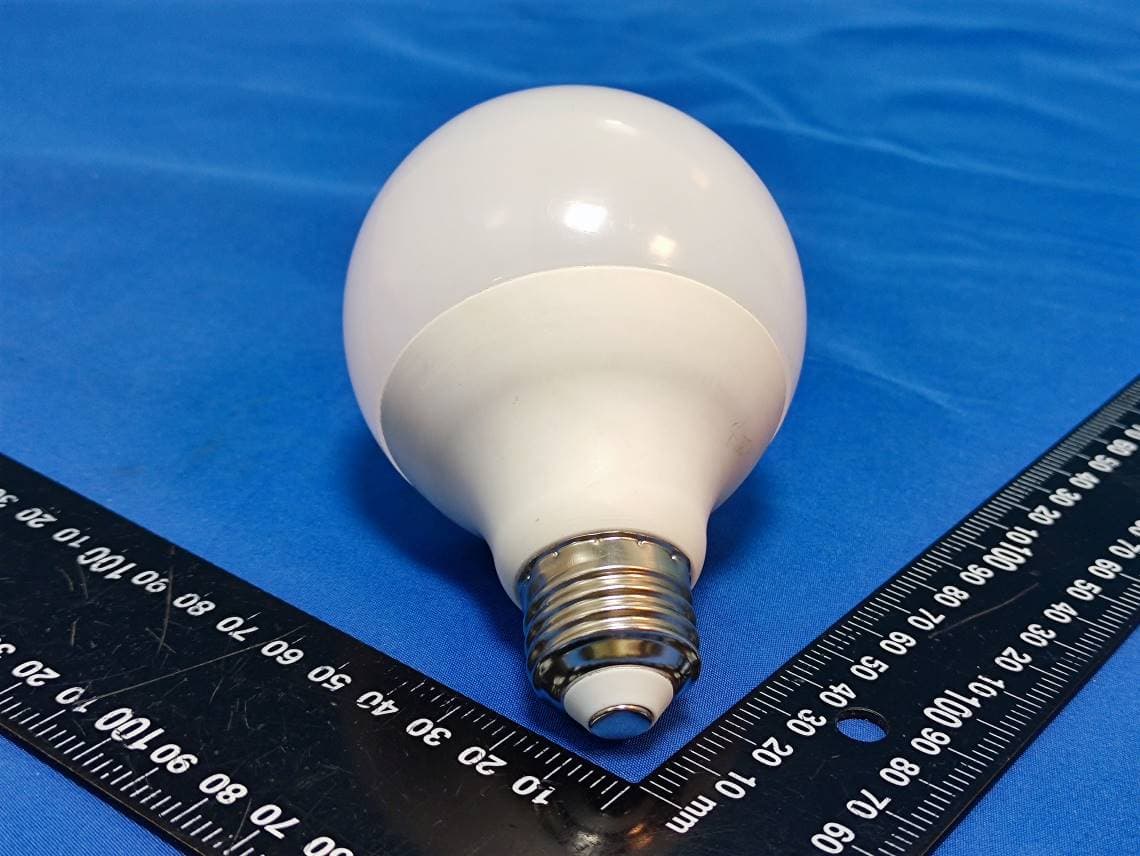
2A9YKG259WRGBTW
Nov 01, 2023LED LAMP
Equipment Class
DTS - Digital Transmission System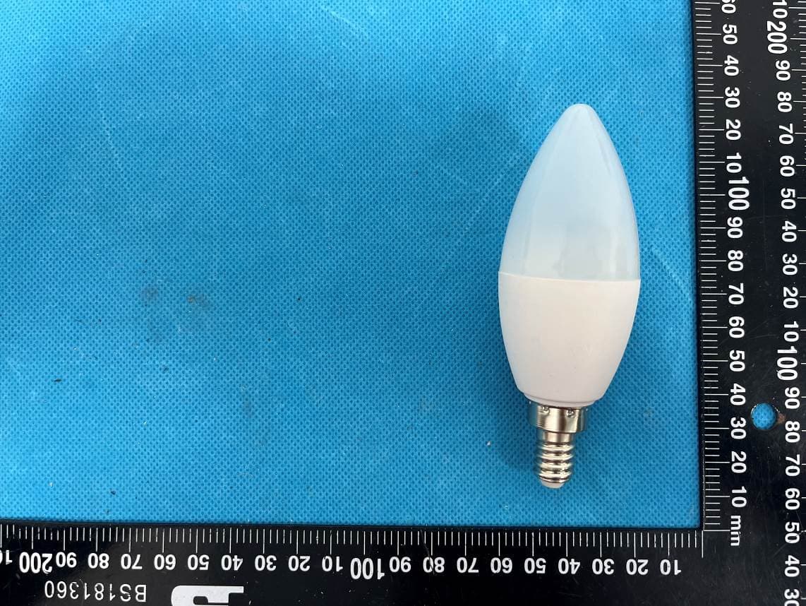
2A9YKB114WRGBTW
Jul 12, 2023LED LAMP
Equipment Class
DTS - Digital Transmission System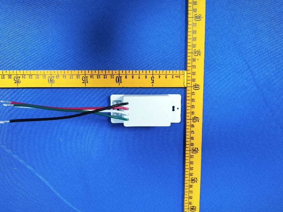
2A9YKCWWTWSCENEWH
Jul 04, 2023Smart Wi-Fi Room Controller
Equipment Class
DTS - Digital Transmission System