2AA7K-ORIONLocation & Monitoring Transmitter
Star Systems International Limited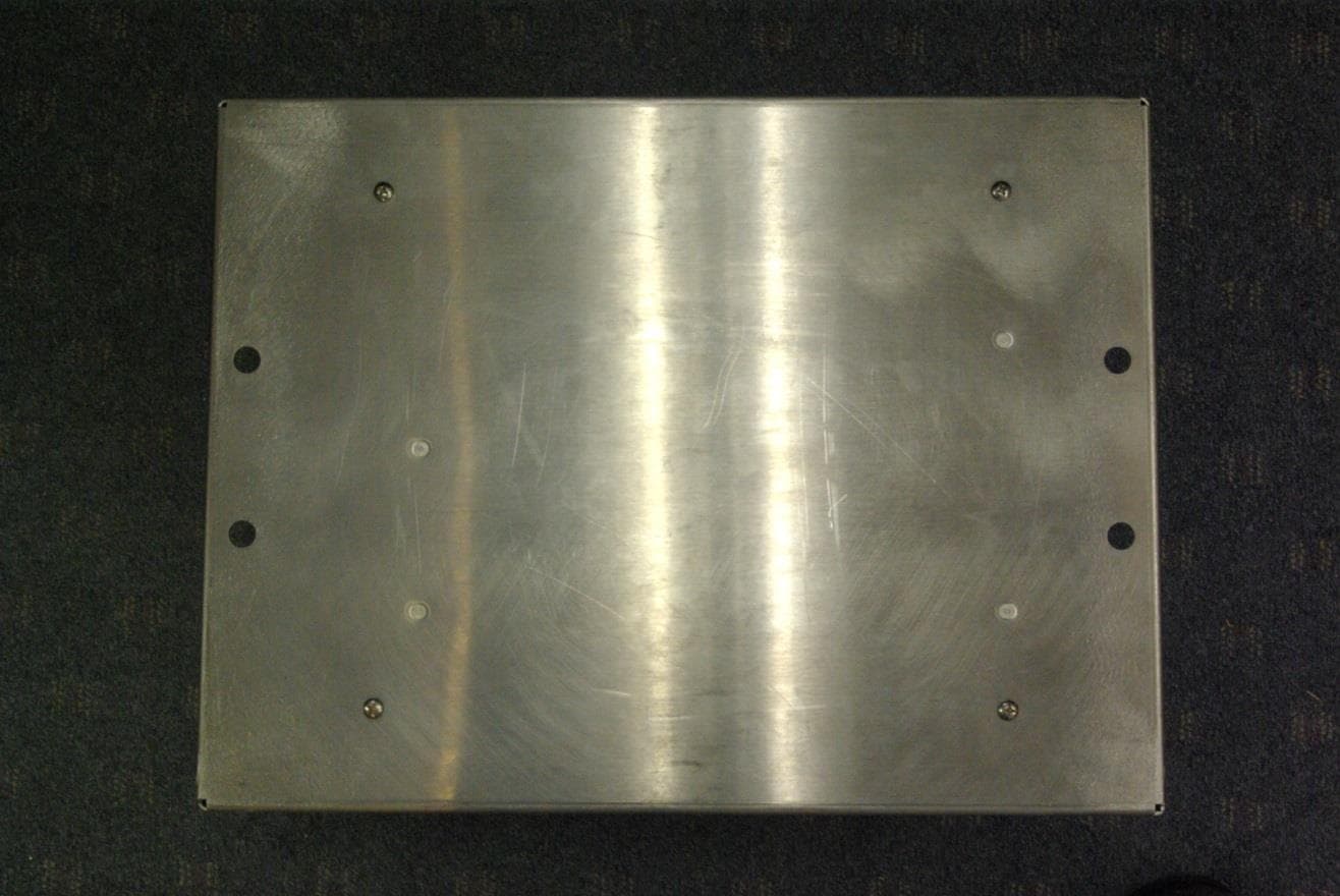
Click to zoom
Application Details
- Equipment Class
- LMS - Part 90 Location & Monitoring Transmitter
- Date of Grant
- May 26, 2015
- Application Purpose
- Original Equipment
- Date of Application
- May 26, 2015
- Equipment Note
- Location & Monitoring Transmitter
- Frequency Range
- 914.75000000 - 916.75000000
- Country
- Hong Kong
Documents & Files
Document Text
Text extracted from the exhibit documents filed with the FCC. Open a document above to read the original.
Users Manual
Orion ® Reader System Guide Star Systems International, Ltd. August 2014 P/N 16-0024-001 Use or disclosure of Proprietary Information contained on this sheet is subject to the restriction stated on the title page of this document.1 Health Limits for Orion® Reader Using External Antenna (902 to 921.5 MHz). . . 1-4 Limites d’innocuité du lecteur OrionMD utilisé avec une antenne externe (902 à 921,5 MHz).................................................... 1-5 Purpose of the Guide................................................. 1-3 Intended Audience................................................... 1-3 Guide Topics........................................................ 1-3 Typographical Conventions Used in this Manual.......................... 1-5 Assessing and Formulating a Site Plan.................................. 2-3 Preparing the Installation Site.......................................... 2-3 Site Preparation Checklist............................................ 2-3 Components Checklist............................................... 2-4 Task Checklist...................................................... 2-4 Where to Mount the Components....................................... 2-4 Overhead Gantry Mount............................................. 2-5 Overpass Mount................................................... 2-6 Cantilever Arm Mount............................................... 2-7 Open Road Tolling Gantry............................................ 2-8 Orion Reader Components............................................ 3-3 Orion Reader Features................................................ 3-4 External Device Connectors.......................................... 3-4 .............................................................. 3-4 Power Supply................................................. 3-5 Selecting a Power Supply....................................... 3-5 Connecting the Orion Reader to Power Supply....................... 3-6 Sync.......................................................... 3-7 External Digital Input/Output Connector............................... 3-8 Connecting to Antenna............................................ 3-8 Connecting to Host Computer.................................... 3-9 Ethernet Connector for TCP Communications........................ 3-9 Connecting to Additional System Components.........................3-10 Diagnostic Communications Connector (COM2).....................3-10 Diagnostic Test Port Internal Connector...........................3-11 Global Positioning System Connector.............................3-11 Installing the Reader System Components..............................3-11 Mounting the Toll Antenna in an Overhead Location......................3-12 Starting the Orion Reader............................................3-14 Orion Reader System Guide 2Use or disclosure of Proprietary Information contained on this sheet is subject to the restriction stated on the title page of this document. Resetting the Orion Reader..........................................3-14 Software Information................................................. 4-3 TCP Command and Response Conventions.............................. 4-3 Lane Controller Heartbeat Controls.................................. 4-4 Sequence Number Controls........................................ 4-4 Data Acknowledge Controls........................................ 4-7 Use of Data Acknowledge Controls by Host and Orion Reader.......... 4-8 Communication Between Orion Reader and Host......................... 5-3 TCP/IP Fast Ethernet Connection...................................... 5-3 TCP/IP Fast Ethernet Communications Protocol.......................... 5-4 Command Request Message....................................... 5-4 Data Acknowledge Message....................................... 5-5 Command Response Message..................................... 5-5 Asynchronous Response Message.................................. 5-5 Unsolicited Status Message........................................ 5-5 Chapter Organization................................................. 6-3 Operating the Orion Reader in Mode 88................................. 6-4 Working with Mode 88............................................... 6-4 System Commands.................................................. 6-6 Command Group Bit Fields........................................ 6-9 Unsolicited Status Bit Field......................................... 6-9 Data Acknowledge Bit Field........................................ 6-9 Responses to System Commands.....................................6-10 Responses and Codes for System Commands...........................6-10 Synchronous Response Bit Field...................................6-11 Asynchronous Response Bit Field..................................6-11 Unsolicited Response Bit Field.....................................6-11 OK Status Bit Field..............................................6-12 Error Status Bit Field.............................................6-12 Control Status Bit Field...........................................6-12 Command Group Command Response Bit Fields......................6-12 System Interface Command Group Commands (8000H)...................6-13 System Interface Command Group Responses..........................6-14 System Interface Command Group Response Data....................6-16 Asynchronous OK Status Responses.............................6-16 Synchronous Error Status Responses.............................6-17 Asynchronous Error Status Responses............................6-18 System Interface Command Group Unsolicited Status Messages............6-20 System Identify...................................................6-21 Set Time and Date................................................6-22 Get Time and Date................................................6-23 Use or disclosure of Proprietary Information contained on this sheet is subject to the restri…
Text truncated - open the document above for the full version.
Cover Letter(s)
April 3, 2015 Timco Engineering Inc. 849 NW State Road 45 Newberry, FL 32669 Office of Engineering and Technology Federal Communications Commission Columbia, MD 21046 Applicant: STAR Systems International, Limited Unit A01, 24/F, Gold King Industrial Building 35-41 Tai Lin Pai Road Kwai Chung, New Territories Hong Kong - SAR Re: Confidentiality for submittal information regarding FCC ID number 2AA7K-ORION PRODUCT: Location and Monitoring Service Transmitter Dear Sirs: STAR Systems International, Limited requests that the material in the Schematics, Block Diagram, Parts List, and Operational Description be withheld from public disclosure pursuant to Sections 0.457 and 0.459 of the Commission’s Rules following grant of the application. In support of this request, STAR Systems International, Limited submits the following: Long Term Confidential Files Include Schematics File Name Conf Schem Orion.pdf Parts List File Name Conf PartList Orion.pdf Block Diagram File Name Conf BlkDia Orion.pdf Operational Description File Name Conf OpDes Orion.pdf 1. Identification of the specific information for which confidential treatment is sought: The materials set forth in the Operational Description, Block Diagram, Parts List, and Schematics, which are segregated from the non-confidential exhibits of the application, are those for which confidentiality is sought. 2. Identification of the Commission proceeding in which the information was submitted or a description of the circumstances giving rise to the submission: The proceeding is that involving the application for equipment authorization (certification) under FCC ID No: 2AA7K-ORION 3. Explanation of the degree to which the information is commercial or financial, or contains a trade secret or is privileged: This material includes a detailed theory of operation, circuit diagrams, schematic diagrams, and any detail Parts List. As such, this material is treated as highly confidential business information. ROGERS LABS, INC. 4405 West 259 th Terrace Louisburg, KS 66053 4. Explanation of the degree to which the information concerns a service that is subject to competition: The material for which confidentiality is sought is employed in the design and manufacture of this transmitting equipment that is offered on a highly competitive basis. Customers for this equipment have a variety of competing sources. 5. Explanation of how disclosure of the information could result in substantial competitive harm: Disclosure would provide competitors the benefits of STAR Systems International, Limited engineering personnel who designed the equipment and the manufacturing process. Disclosure would also offer competitors additional unwarranted insight into the state of the product development, thereby allowing competitors an advantage, not available to STAR Systems International, Limited. 6. Identification of any measures taken by the submitting party to prevent unauthorized disclosure: The information for which confidential treatment is sought is kept confidential by STAR Systems International, Limited and not made available to third parties except pursuant to non-disclosure agreements. 7. Identification of whether the information is available to the public and the extent of any previous disclosure of the information to third parties: To the knowledge of those preparing this application, the information has not been disclosed publicly heretofore. While the general theory of operation of this equipment has been the subject of numerous disclosures in industry and standards groups as well as in rule making proceedings of the FCC, the protection sought is narrowly drawn and pertains to certain specific implementations of this radio technology. 8. Justification of the period during which the submitting party asserts that the material should not be available for public disclosure: This material should not be disclosed for at least 25 years. While improvements in design occur, disclosure of the design information would lead to insights into both design and manufacturing techniques that could have an adverse competitive effect for many years to come. As such, it is important that the design not be made available to unauthorized persons who might attempt to use knowledge of the design to compromise the applications for which the equipment will be employed. Should you require any further information, please contact the undersigned. Thank you for your consideration in this matter. Sincerely, Scot Rogers
Cover Letter(s)
April 3, 2015 Timco Engineering Inc. 849 NW State Road 45 Newberry, FL 32669 Federal Communications Commission Equipment Approval Services P.O. Box 35815 Pittsburgh, PA 15251-3315 Applicant: STAR Systems International, Limited Unit A01, 24/F, Gold King Industrial Building 35-41 Tai Lin Pai Road Kwai Chung, New Territories Hong Kong - SAR Equipment: FCC ID: 2AA7K-ORION FCC Rules: Location and Monitoring Service Transmitter Men: The form 731 and application have been electronically submitted and any attachments will be provided to your site to be used in processing for and obtaining grant of authorization. Permanent Confidential Requested STAR Systems International, Limited requests that the material in the Parts List, Schematics, Block Diagram, and Operational Description be withheld from public disclosure pursuant to Sections 0.457 and 0.459 of the Commission’s Rules following grant of the application. In support of this request, STAR Systems International, Limited submits the following files to hold in long-term confidential status. Schematics File Name Conf Schem Orion.pdf Parts List File Name Conf PartList Orion.pdf Block diagram File Name Conf BlkDia Orion.pdf Operational Description File Name Conf OpDes Orion.pdf Should you require any further information, please contact the undersigned. Thank you for your consideration in this matter. Sincerely, Scot Rogers Rogers Labs, Inc. Enclosures ROGERS LABS, INC. 4405 West 259 th Terrace Louisburg, KS 66053 Phone / Fax (913) 837-3214
External Photos
Rogers Labs, Inc. STAR Systems International, Limited 4405 W. 259th Terrace Model: Orion S/N: 4124359 FCC ID#: 2AA7K-ORION Louisburg, KS 66053 Test #: 150203 IC: 20068-ORION Telephone/Fax: (913) 837-3214 Test to: CFR47 Parts 2, 90 and RSS-137 Date: May 15, 2015 Revision 1 File: ExtPho Orion Page 1 of 3 External photographs of equipment under test Rogers Labs, Inc. STAR Systems International, Limited 4405 W. 259th Terrace Model: Orion S/N: 4124359 FCC ID#: 2AA7K-ORION Louisburg, KS 66053 Test #: 150203 IC: 20068-ORION Telephone/Fax: (913) 837-3214 Test to: CFR47 Parts 2, 90 and RSS-137 Date: May 15, 2015 Revision 1 File: ExtPho Orion Page 2 of 3 Rogers Labs, Inc. STAR Systems International, Limited 4405 W. 259th Terrace Model: Orion S/N: 4124359 FCC ID#: 2AA7K-ORION Louisburg, KS 66053 Test #: 150203 IC: 20068-ORION Telephone/Fax: (913) 837-3214 Test to: CFR47 Parts 2, 90 and RSS-137 Date: May 15, 2015 Revision 1 File: ExtPho Orion Page 3 of 3
ID Label/Location Info
Rogers Labs, Inc. STAR Systems International, Limited 4405 W. 259th Terrace Models: Orion S/N: 4124359 FCC ID#: FCC:fccidfccid Louisburg, KS 66053 Test #: 150203 IC: 12345A-ICicICic Telephone/Fax: (913) 837-3214 Test to: CFR47 Parts 2, 90 and RSS-137 Date: May 8, 2015 Revision 1 File: LabelSmpl Orion Page 1 of 1 Label and Placement LABEL
Internal Photos
Rogers Labs, Inc. STAR Systems International, Limited 4405 W. 259th Terrace Model: Orion S/N: 4124359 FCC ID#: 2AA7K-ORION Louisburg, KS 66053 Test #: 150203 IC: 20068-ORION Telephone/Fax: (913) 837-3214 Test to: CFR47 Parts 2, 90 and RSS-137 Date: May 19, 2015 Revision 1 File: IntPho Orion 3 Page 1 of 1 Internal photographs of equipment under test Power Supply Power Distribution Multiplexer Digital interface Transmitter Transmitter Digital interface GPS Receiver
Internal Photos
Orion Overview Photo Orion Digital Board Photos (front and back) Ethernet Adapter Photos (Front and Back) FPGA2 Board Photos (Front and Back) Power Supply Board Photos (Front and Back) Transceiver Board Photos (Front and Back) Multiplexer Photos (Front and Back)
Parts List/Tune Up Info
Orion Tune-Up Procedure The transmitter’s power output level is controlled by an Automatic Level Control (ALC) circuit. The Orion's maximum output power level of 32dBm is calibrated on each unit at the factory at the center frequency of 912.00MHz. The calibration accuracy is +/- 0.2dB and the power output level tolerance across the band is +/- 0.5dB.
RF Exposure Info
Rogers Labs, Inc. STAR Systems International, Limited 4405 W. 259th Terrace Model: Orion S/N: 4124359 FCC ID#: 2AA7K-ORION Louisburg, KS 66053 Test #: 150203 IC: 20068-ORION Telephone/Fax: (913) 837-3214 Test to: CFR47 Parts 2, 90 and RSS-137 Date: May 19, 2015 Revision 1 File: RFExp Orion Page 1 of 1 Industry Canada
Test Report
NVLAP Lab Code: 200087-0 Rogers Labs, Inc. STAR Systems International, Limited 4405 W. 259th Terrace Model: Orion S/N: 4124359 FCC ID#: 2AA7K-ORION Louisburg, KS 66053 Test #: 150203 IC: 20068-ORION Telephone/Fax: (913) 837-3214 Test to: CFR47 Parts 2, 90 and RSS-137 Date: May 26, 2015 Revision 1 File: Star Sys Orion TstRpt 150203150526 Page 1 of 39 Test Report CFR47 Part 90 and Industry Canada RSS-137 Application for Grant of Certification Model: Orion Location and Monitoring Service Transmitter 902.25 - 903.75 and 910.00 – 921.50 MHz FCC ID: 2AA7K-ORION IC: 20068-ORION FOR STAR Systems International, Limited Unit A01, 24/F, Gold King Industrial Building 35-41 Tai Lin Pai Road Kwai Chung, New Territories Hong Kong - SAR Report Number 150203 Authorized Signatory: Scot D. Rogers NVLAP Lab Code: 200087-0 Rogers Labs, Inc. STAR Systems International, Limited 4405 W. 259th Terrace Model: Orion S/N: 4124359 FCC ID#: 2AA7K-ORION Louisburg, KS 66053 Test #: 150203 IC: 20068-ORION Telephone/Fax: (913) 837-3214 Test to: CFR47 Parts 2, 90 and RSS-137 Date: May 26, 2015 Revision 1 File: Star Sys Orion TstRpt 150203150526 Page 2 of 39 Test Report For Application of Certification For STAR Systems International, Limited Unit A01, 24/F, Gold King Industrial Building 35-41 Tai Lin Pai Road Kwai Chung, New Territories Hong Kong - SAR Model: Orion Location Monitoring Service Transmitter Frequency: 902.25 - 903.75 and 910.00 – 921.50 MHz FCC ID: 2AA7K-ORION IC: 20068-ORION Test Date: February 3, 2015 Certifying Engineer: Scot D. Rogers Rogers Labs, Inc. 4405 W. 259th Terrace Louisburg, KS 66053 Telephone / Facsimile: (913) 837-3214 This report shall not be reproduced except in full, without the written approval of the laboratory. This report must not be used by the client to claim product endorsement by NVLAP, NIST or any agency of the U.S. Government. ROGERS LABS, INC. 4405 West 259 th Terrace Louisburg, KS 66053 Telephone / Fax (913) 837-3214 NVLAP Lab Code: 200087-0 Rogers Labs, Inc. STAR Systems International, Limited 4405 W. 259th Terrace Model: Orion S/N: 4124359 FCC ID#: 2AA7K-ORION Louisburg, KS 66053 Test #: 150203 IC: 20068-ORION Telephone/Fax: (913) 837-3214 Test to: CFR47 Parts 2, 90 and RSS-137 Date: May 26, 2015 Revision 1 File: Star Sys Orion TstRpt 150203150526 Page 3 of 39 Table Of Contents TABLE OF CONTENTS .................................................................................................... 3 REVISION HISTORY ........................................................................................................ 4 OPINION / INTERPRETATION OF RESULTS ................................................................. 5 APPLICATION FOR CERTIFICATION ............................................................................. 6 EQUIPMENT TESTED ...................................................................................................... 8 Equipment Operation and Test Setup .................................................................................................................... 8 Test Setup Diagram .................................................................................................................................................. 8 APPLICABLE STANDARDS AND TEST PROCEDURES ............................................... 9 UNITS OF MEASUREMENTS .......................................................................................... 9 TEST SITE LOCATIONS .................................................................................................. 9 ENVIRONMENTAL CONDITIONS.................................................................................... 9 LIST OF TEST EQUIPMENT ............................................................................................ 10 TRANSMITTER POWER OUTPUT .................................................................................. 11 Measurements Required .......................................................................................................................................... 11 Test Arrangement ..................................................................................................................................................... 11 Table 1 Transmitter Power Results ......................................................................................................................... 12 Figure 1 Power output at antenna terminal (CW operation)................................................................................... 13 Figure 2 Power output at antenna terminal (Modulated operation) ........................................................................ 13 Figure 2a Power output at antenna terminal (Modulated operation) ...................................................................... 14 Figure 2b Power output at antenna terminal (0 and 15 dB attenuation) ................................................................. 14 MODULATION CHARACTERISTICS ............................................................................... 15 Measurements Required .......................................................................................................................................... 15 Test Arrangement ..................................................................................................................................................... 15 Results Modulation Characteristics ........................................................................................................................ 15 OCCUPIED BANDWIDTH ................................................................................................ 15 Measurements Required .......................................................................................................................................... 15 Test Arrangement ...............................................................................................................................................…
Text truncated - open the document above for the full version.
Test Setup Photos
Rogers Labs, Inc. STAR Systems International, Limited 4405 W. 259th Terrace Model: Orion S/N: 4124359 FCC ID#: 2AA7K-ORION Louisburg, KS 66053 Test #: 150203 IC: 20068-ORION Telephone/Fax: (913) 837-3214 Test to: CFR47 Parts 2, 90 and RSS-137 Date: May 3, 2015 Revision 1 File: TSup Orion Page 1 of 1 Test setup photographs
Contact Information
Applicant
Ava Tang(COO)
Test Firm
Rogers Labs, Inc.Scot Rogers
Technical Specifications
| # | Rule Parts | Frequency Range | Power Output | Emission | Tolerance |
|---|---|---|---|---|---|
| 6 | 90.353 | 914.75 MHz - 916.75 MHz | 1.6 W | 1M76A1D | 2.5 ppm |
Other Applications from Star Systems International Limited

2AA7KTARVOSPRO31000
Jun 23, 2024Tarvos Pro
Equipment Class
LMS - Part 90 Location & Monitoring Transmitter
2AA7KSOLARIA29000
May 01, 2023SOLARIA
Equipment Class
DSS - Part 15 Spread Spectrum Transmitter
2AA7KTARVOSHRD27000
Jul 20, 2020INTEGRATED READER
Equipment Class
DSS - Part 15 Spread Spectrum Transmitter
2AA7KRANGER-HRD1800
Oct 27, 2015Desktop USB Reader
Equipment Class
DSS - Part 15 Spread Spectrum Transmitter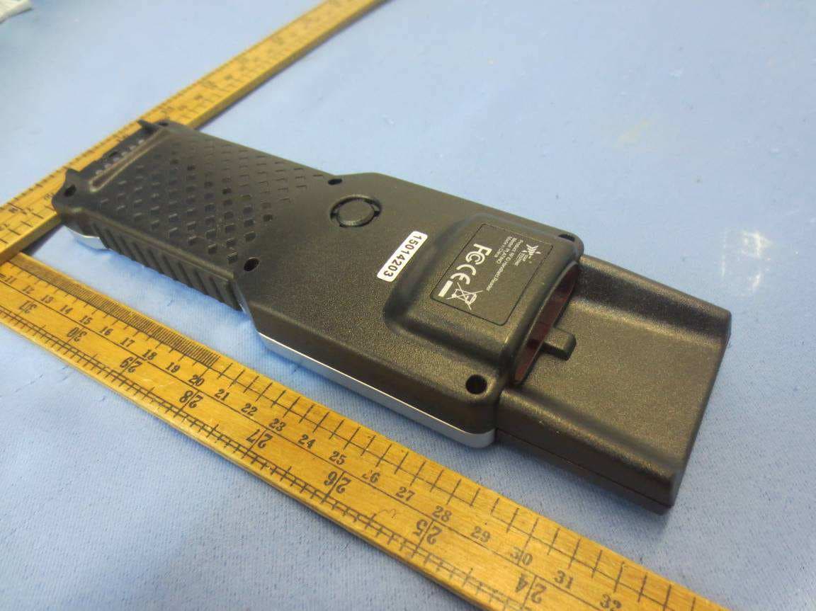
2AA7KPLATINO-WF2014
Sep 12, 2015RFID Handheld Reader
Equipment Class
DSS - Part 15 Spread Spectrum Transmitter