2AAFH-CD95BTCD Player
Winsonic Electric Limited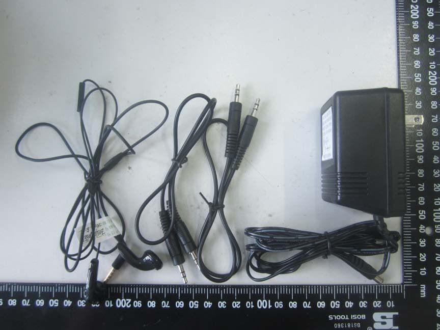
Click to zoom
Application Details
- Equipment Class
- DSS - Part 15 Spread Spectrum Transmitter
- Date of Grant
- Jul 29, 2014
- Application Purpose
- Original Equipment
- Date of Application
- Jul 29, 2014
- Equipment Note
- CD Player
- Frequency Range
- 2402.00000000 - 2480.00000000
- Company
- Winsonic Electric Limited
- Country
- Hong Kong
Documents & Files
Document Text
Text extracted from the exhibit documents filed with the FCC. Open a document above to read the original.
Users Manual
1 CD PLAYER CD95BT OPERATING INSTRUCTIONS BEFORE OPERATION THIS PRODUCT, READ, UNDERSTAND, AND FOLLOW THESE INSTRUCTIONS. 2 Be sure to save this booklet for future reference. SAFETY INSTRUCTIONS WARNING : TO REDUCE THE RISK OF FIRE OR ELECTRIC SHOCK, DO NOT EXPOSE THE APPLIANCE TO RAIN OR MOISTURE. SAFETY INSTRUCTIONS 1. Read instructions - All the safety and operating instructions should be read before the appliance is operated. 2. Retain instructions - The safety and operating instructions should be retained for future reference. 3. Head Warnings - All warnings and cautions on the appliance and in the operating instructions should be adhered to. 4. Follow instructions - All operating and use instructions should be followed. 5. Water and Moisture - The appliance should not be used near water, e.g. near a bathtub, washbowl, kitchen sink, laundry tub, in a wet basement, or near a swimming pool or the like. 6. Ventilation - The appliance should be situated so that its location or position does not interfere with its proper ventilation. For example, the appliance should not be situated on a bed, sofa, rug or similar surface that may block the ventilation openings, or placed in a built-in installation, such as a bookcase or cabinet, that may impede the flow of air through the ventilation openings. 3 7. Heat - The appliance should be situated away from neat sources such as radiators, heat registers, stoves, or other appliances (including amplifiers) that produce heat.. 8. Power Sources - The product should be operated only with the type of power supply indicated on the marking label. 9. Grounding Polarization - This product may be equipped with a polarized alternating current line plug (a plug having one blade wider than the other). This plug will fit into the power outlet only one way this is a safety feature. 10. Power-Cord Protection - Power supply cords should be routed so that they are not likely to be walked on or pinched by items placed upon or against them, paying particular attention to cords at plugs, convenience receptacles, and the point where they exit from the appliance. 11. Nonuse periods - The power cord of the appliance should be unplugged from the outlet when left when left unused for a long period of time. 12. Object and Liquid Entry - Care should be taken so that objects do not fall and liquids are not spilled into the product case through product openings. 13. Damage Requiring Service - Unplug this product from the wall outlet and take it to qualified service personnel under the following conditions. a) When the power-supply cord or plug is damaged. b) If liquid has been spilled into, or objects have fallen into the product. c) If the product has been exposed to rain or water. d) If the product does not operate when used according to the operating instructions. e) If the product has been dropped or damaged in any way. 14. Servicing - The user should not attempt to service the product beyond that described in the operating instruction. All servicing should be referred to qualified service personnel. CAUTION Invisible laser radiation will be emitted when the product is open and interlocks are defeated. Do not defeat the safety interlocks. USE OF CONTROLS, ADJUSTMENTS, OR PERFORMANCE PROCEDURE HEREIN MAY RESULT IN HAZARDOUS RADIATION EXPOSURE. 4 LOCATIONS OF CONTROLS 1. REWIND 2. PLAYMODE PROG/MEM 3. FAST FORWARD 4. PLAY/PAUSE/ MEMORY DOWN 5. LCD DISPLAY 6. STOP/ MEMORY UP 7. VOLUME - 8. STANDBY/FUNCTION 9. VOLUME + 10. SPEAKER 1 11. SPEAKER 2 12. CD DOOR OPEN 13. HANDLE 14. AUX JACK 15. PHONE JACK 16. ADAPTOR JACK POWER SUPPLY Operate by DC Batteries (not included) Open the battery compartment and insert eight batteries, UM-2 or C-cells, (preferably Alkaline) with the correct polarity as indicated by the "+" and "–" symbols inside the compartment. Incorrect use of batteries can cause electrolyte leakage and will corrode the compartment or cause the batteries to burst. Therefore: • Do not mix battery types: e.g. alkaline with carbon zinc. Only use batteries of the same type for the set. • When inserting new batteries, do not try to mix old batteries with the new ones. • Remove the batteries if the set is not to be used for a long time. 5 Unit power supply (mains AC 120V/60Hz) 1. Check if the power voltage, as shown on the type plate located on the bottom of the set, corresponds to your local AC power supply. 2. Connect the power cord to the AC MAINS inlet and the wall outlet. The power supply is now connected and ready for use. 3. To switch off completely, unplug the power cord from the wall outlet. Basic Function Switching power STANDBY to save energy 1. Press and Hold the STANDBY FUNCTION button to turn off the Unit. 2. The display will show nothing and it indicates that the Device is off. 3. Whether you are using mains or battery supply, to avoid unnecessary energy consumption always adjust the source selector to STANDBY. General operation 1. To select your sound source adjust the source STANDBY/AUX/RADIO/CD MP3/BLUETOOTH 2. Adjust the sound with the VOLUME -, VOLUME + Button 3. To switch off the set, adjust the source selector to STANDBY position. RADIO OPERATION Radio reception 1. Slide the STANDBY/AUX/RADIO/CD MP3 selector to AM or FM 2. Use the FAST FORWARD BUTTON and the REWIND BUTTON to adjust the radio frequency– 3. Use the Vo NOTE: If FM is selected, Display will show FM on screen. This goes the same with AM. 4. When you have finished listening, slide the STANDBY/AUX/RADIO/CD MP3 selector to the STANDBY position to turn off the unit. For better reception - For FM, pull out the soft antenna. Let the Atenna reach a further open area for better reception. Radio Preset The tracks on the disc can be programmed to play in any order (up to 20) tracks can be programmed). 1. Press the F.FWD or REW buttons to select the frequency to be preset. 2. Press the PROG button while in stop mode. Program number ‘P01” will flash and shown in the display. 3. Press the PROG button agai…
Text truncated - open the document above for the full version.
External Photos
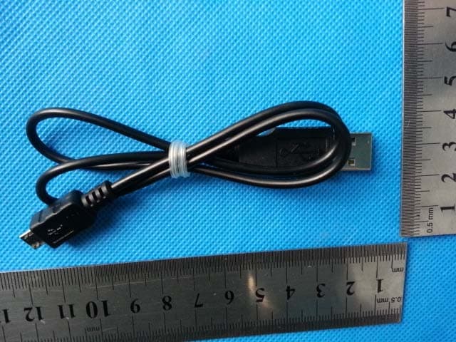
SZ14060146-External Photos External Photos 1. EUT front view SZ14060146-External Photos 2. EUT rear view 3. EUT left side view SZ14060146-External Photos 4. EUT right side view 5. EUT top view SZ14060146-External Photos 6. EUT bottom view 7. Accessories
ID Label/Location Info
FCC label and label location 1. Label 2. Label location
Internal Photos
SZ14060146-Internal Photos Internal Photos 1. EUT uncover view SZ14060146-Internal Photos SZ14060146-Internal Photos 2. Mainboard front view 3. Mainboard rear view SZ14060146-Internal Photos 4. Sub board front view 5. Sub board rear view SZ14060146-Internal Photos 6. BT chip view SZ14060146-Internal Photos 7. BT antenna view 8. FM antenna view
Test Report
Report No.:SZ14060146W01A Shenzhen Morlab Communications Technology Co., Ltd Phone: +86 (0) 755 36698555 Web site: http://www.morlab.cn/ Fax: +86 (0) 755 36698525 Email: [email protected] Page 2 of 76 TABLE OF CONTENTS 1. GENERAL INFORMATION ...................................................................................................................... 5 1.1. EUT DESCRIPTION .................................................................................................................................. 5 1.2. TEST STANDARDS AND RESULTS ............................................................................................................. 6 1.3. FACILITIES AND ACCREDITATIONS ............................................................................................................ 7 1.3.1. FACILITIES ....................................................................................................................................................... 7 1.3.2. TEST ENVIRONMENT CONDITIONS ................................................................................................................ 7 2. 47 CFR PART 15C REQUIREMENTS .................................................................................................... 8 2.1. ANTENNA REQUIREMENT ......................................................................................................................... 8 2.1.1. APPLICABLE STANDARD ................................................................................................................................. 8 2.1.2. RESULT: COMPLIANT ...................................................................................................................................... 8 2.2. NUMBER OF HOPPING FREQUENCY ......................................................................................................... 8 2.2.1. REQUIREMENT ................................................................................................................................................ 8 2.2.2. TEST DESCRIPTION ........................................................................................................................................ 8 2.2.3. TEST PROCEDURE ......................................................................................................................................... 9 2.2.4. TEST RESULT .................................................................................................................................................. 9 2.3. PEAK OUTPUT POWER ........................................................................................................................... 13 2.3.1. REQUIREMENT .............................................................................................................................................. 13 2.3.2. TEST DESCRIPTION ...................................................................................................................................... 13 2.3.3. TEST RESULT ................................................................................................................................................ 13 2.3.3.1. GFSK MODE ............................................................................................................................................. 14 2.3.3.2. ∏/4-DQPSK MODE ................................................................................................................................. 14 2.3.3.3. 8-DPSK MODE ......................................................................................................................................... 14 2.4. 20DB BANDWIDTH .................................................................................................................................. 15 2.4.1. DEFINITION ................................................................................................................................................... 15 2.4.2. TEST DESCRIPTION ...................................................................................................................................... 15 2.4.3. TEST PROCEDURE ....................................................................................................................................... 15 2.4.4. TEST RESULT ................................................................................................................................................ 16 2.4.4.1. GFSK MODE ............................................................................................................................................. 16 2.4.4.2. ∏/4-DQPSK MODE ................................................................................................................................. 18 2.4.4.3. 8-DPSK MODE ......................................................................................................................................... 20 2.5. CARRIED FREQUENCY SEPARATION ....................................................................................................... 22 2.5.1. DEFINITION ................................................................................................................................................... 22 2.5.2. TEST DESCRIPTION ...................................................................................................................................... 22 2.5.3. TEST PROCEDURE ....................................................................................................................................... 22 2.5.4. TEST RESULT ................................................................................................................................................ 23 Report No.:SZ14060146W01A Shenzhen Morlab Communications Technology Co., Ltd Phone: +86 (0) 755 36698555 Web site: http://www.morlab.cn/ Fax: +86 (0) 755 36698525 Email: [email protected] Page 3 of 76 2.6. TIME OF OCCUPANCY (DWELL TIME) ......…
Text truncated - open the document above for the full version.
Test Setup Photos
SZ14060146W01-Photo Test Setup Photos 1. Conducted emission main’s port front view 2. Conducted emission main’s port side view SZ14060146W01-Photo 3. Radiated emission (9KHz-30MHz) 4. Radiated emission (30MHz-1GHz) SZ14060146W01-Photo 5. Radiated emission (above 1GHz) 6. Conducted emission antenna’s port
Contact Information
Applicant
Mimi Chan(Merchandiser)
Test Firm
Shenzhen Morlab Communications Technology Co., LtdIvy zhu
Technical Specifications
| # | Rule Parts | Frequency Range | Power Output |
|---|---|---|---|
| 1 | 15C | 2.40 GHz - 2.48 GHz | 700.00 µW |
Other Applications from Winsonic Electric Limited
2AAFH-SPK128
Apr 28, 2015Portable Speaker System
Equipment Class
DSS - Part 15 Spread Spectrum Transmitter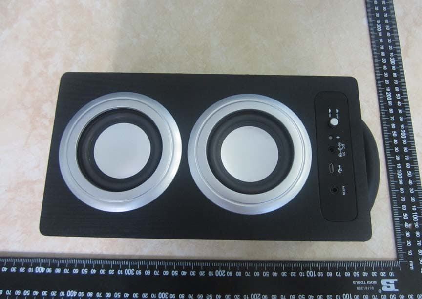
2AAFH-WM2899
Aug 30, 2014Bluetooth speaker
Equipment Class
DSS - Part 15 Spread Spectrum Transmitter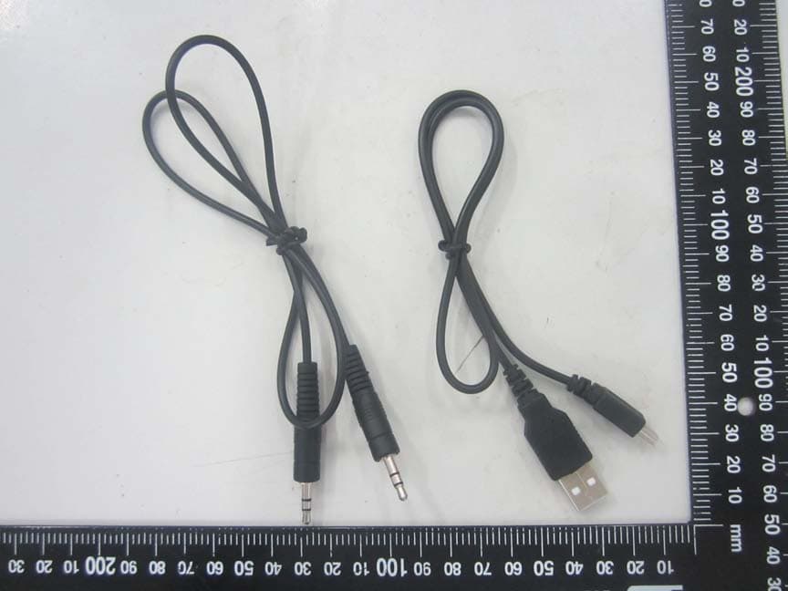
2AAFH-WO240
Aug 17, 2014Bluetooth speaker
Equipment Class
DSS - Part 15 Spread Spectrum Transmitter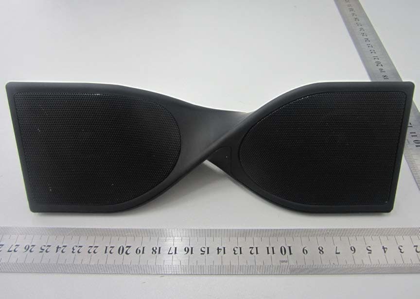
2AAFH-SPK109
Dec 09, 2013BLUETOOTH SPEAKER
Equipment Class
DSS - Part 15 Spread Spectrum Transmitter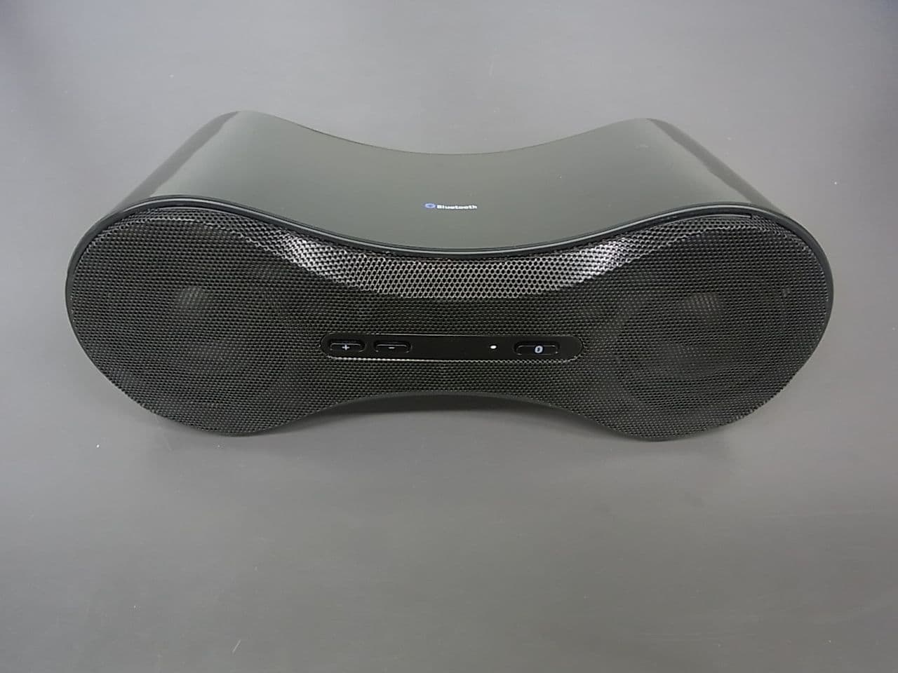
2AAFH-SPK90A
May 30, 2013BLUETOOTH SPEAKER
Equipment Class
DSS - Part 15 Spread Spectrum Transmitter