2AAFH-SPK109BLUETOOTH SPEAKER
Winsonic Electric Limited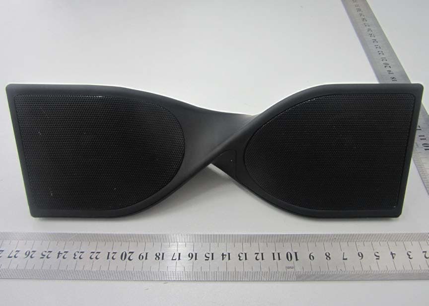
Click to zoom
Application Details
- Equipment Class
- DSS - Part 15 Spread Spectrum Transmitter
- Date of Grant
- Dec 09, 2013
- Application Purpose
- Original Equipment
- Date of Application
- Dec 09, 2013
- Equipment Note
- BLUETOOTH SPEAKER
- Frequency Range
- 2402.00000000 - 2480.00000000
- Company
- Winsonic Electric Limited
- Country
- Hong Kong
Documents & Files
Document Text
Text extracted from the exhibit documents filed with the FCC. Open a document above to read the original.
Users Manual
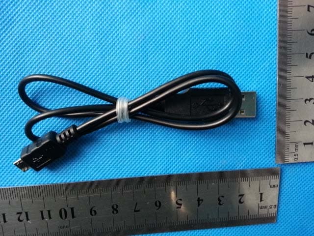
WINSONIC SPK109 Bluetooth Speaker LOCATION OF CONTROLS 1. Left Speaker Grill 2. Right Speaker Grill 3. Vol + Button 4. Forward button 5. Vo l - Button 6. Play/Pause 7. Backward Button 8. USB Charging 9. OFF/ON switch 10. AUX Jack How to connect the SPK109 to your Bluetooth device 1. Make sure your speaker is charged (follow charge instruction) 2. Slide the ON/OFF Switch to ON position, the LED will turn flash green indicating it is searching. 3. Turn on the Bluetooth feature on your mobile compatible device. Search for MERKURY SPB09. Pair and connect to MERKURY SPB09. If pairing is successful, the LED light will stay on in GREEN. 4. You can now start playing your music How to connect the SPK109 to Aux function 1. Make sure your speaker is charged (follow charge instruction) 2. Slide the ON/OFF Switch to ON position, the LED will turn flash green indicating it is searching. 3. Connect the aux cable to the aux input at the back of the unit 4. Connect the other end to the headphone output(3.5mm)of your smartphone or other device, the LED light will turn off. 5. You can now start playing your music Volume: In Bluetooth mode To turn up the volume, press the Vol+ Button To turn down the volume, press the Vol- Button NOTE: Volume can also be adjusted on your Bluetooth Compatible Device, consult your Bluetooth Compatible Device’s manual for instructions. Pause your music Press the play/pause button to play or pause your music Forward/backward music If you want play the next song or previous song, press the backward or forward button Charge the Built-in Li-Ion Battery 1. Connect the mini USB cable at the back of the speaker. (USB charging) 2. Connect the other end of the cable to a USB port or to a USB AC adapter. (not included) This device complies with part 15 of the FCC rules. Operation is subject to the following two conditions: (1) this device may not cause harmful interference, and (2) this device must accept any interference received, including interference that may cause undesired operation. NOTE: The manufacturer is not responsible for any radio or TV interference caused by unauthorized modifications or changes to this equipment. Such modifications or changes could void the user’s authority to operate the equipment. Power is so low that no RF exposure calculation is needed.
Cover Letter(s)
Date: Dec 04, 2013 To: Federal Communications Commission, Authorization & Evaluation Division, 7435 Oakland Mills Road, Columbia, MD 21046 To Whom It May Concern: Winsonic Electric Limited the undersigned, hereby authorizes Ms. Ivy Zhu from Shenzhen Morlab Communications Technology Co., Ltd., to act on the behalf of Winsonic Electric Limited solely in matters relating to the application for an FCC equipment authorization for FCC ID: 2AAFH-SPK109 including the signing of documents in connection with this Application. Necessary acts carried out by Shenzhen Morlab Communications Technology Co., Ltd on our behalf of Winsonic Electric Limited in connection with the Application shall have the same effect as acts of Winsonic Electric Limited. Winsonic Electric Limited also hereby certify that no party to this application is subject to a denial of benefits, including FCC benefits, pursuant to Section 5301 of the Anti- Drug Abuse Act of 1988, 21 U.S.C. 853(a). Thank you for your attention to this matter. Signatory Mimi Chan Winsonic Electric Limited
Cover Letter(s)
Date: Dec 04, 2013 To: Federal Communications Commission, Authorization & Evaluation Division, 7435 Oakland Mills Road, Columbia, MD 21046 Re: Winsonic Electric Limited FCC ID: 2AAFH-SPK109 FCC Part 15C Certification Confidentiality Request Gentlemen: This letter is to comply with 47 CFR 0.457 and 0.459 pertaining to confidentiality material.TCT Mobile Limited requests that the following documents regarding this submission for FCC ID: 2AAFH-SPK109 be kept confidential: Exhibit Type File Name Block Diagram Block Diagram.pdf Schematics Schematics.pdf Operational Description Operational Description.pdf Part list BOM.pdf Those documents contain detailed system and equipment description and related information about the product which Winsonic Electric Limited considers to be confidential proprietary, a custom design and, otherwise, not releasable to the general public. Since this design is a basis form which future technological products will evolve, Winsonic Electric Limited considers this information would be of benefit to its competitors, and that the disclosure of the information in these documents would give competitors an unfair advantage in the market. Signatory Mimi Chan Winsonic Electric Limited
External Photos
External Photos 1. EUT front view 2. EUT rear view 3. EUT bottom view 4. EUT left side view 5. EUT right side view
ID Label/Location Info
FCC label and label location 1. Label SIZE: 4cm*3cm 2. Label location Label location
Internal Photos
Internal Photos 1. EUT uncover view 2. Mainboard front view 3. Mainboard rear view 4. Key board front view 5. Key board rear view 6. BT chip view 7. BT antenna view
Test Report
Report No.:SZ13110040W02 Shenzhen Morlab Communications Technology Co., Ltd Phone: +86 (0) 755 36698555 Web site: http://www.morlab.cn/ Fax: +86 (0) 755 36698525 Email: [email protected] Page 2 of 46 TABLE OF CONTENTS 1. GENERAL INFORMATION ...................................................................................................................... 4 1.1. EUT DESCRIPTION .................................................................................................................................. 4 1.2. TEST STANDARDS AND RESULTS ............................................................................................................. 5 1.3. FACILITIES AND ACCREDITATIONS ............................................................................................................ 6 1.3.1. FACILITIES ....................................................................................................................................................... 6 1.3.2. TEST ENVIRONMENT CONDITIONS ................................................................................................................ 6 2. 47 CFR PART 15C REQUIREMENTS .................................................................................................... 7 2.1. ANTENNA REQUIREMENT ......................................................................................................................... 7 2.1.1. APPLICABLE STANDARD ................................................................................................................................. 7 2.1.2. RESULT: COMPLIANT ...................................................................................................................................... 7 2.2. NUMBER OF HOPPING FREQUENCY ......................................................................................................... 7 2.2.1. REQUIREMENT ................................................................................................................................................ 7 2.2.2. TEST DESCRIPTION ........................................................................................................................................ 7 2.2.3. TEST PROCEDURE ......................................................................................................................................... 8 2.2.4. TEST RESULT .................................................................................................................................................. 8 2.3. PEAK OUTPUT POWER ........................................................................................................................... 10 2.3.1. REQUIREMENT .............................................................................................................................................. 10 2.3.2. TEST DESCRIPTION ...................................................................................................................................... 10 2.3.3. TEST RESULT ................................................................................................................................................ 10 2.3.3.1. GFSK MODE ............................................................................................................................................. 11 2.4. 20DB BANDWIDTH .................................................................................................................................. 12 2.4.1. DEFINITION ................................................................................................................................................... 12 2.4.2. TEST DESCRIPTION ...................................................................................................................................... 12 2.4.3. TEST PROCEDURE ....................................................................................................................................... 12 2.4.4. TEST RESULT ................................................................................................................................................ 13 2.4.4.1. GFSK MODE ............................................................................................................................................. 13 2.5. CARRIED FREQUENCY SEPARATION ....................................................................................................... 15 2.5.1. DEFINITION ................................................................................................................................................... 15 2.5.2. TEST DESCRIPTION ...................................................................................................................................... 15 2.5.3. TEST PROCEDURE ....................................................................................................................................... 15 2.5.4. TEST RESULT ................................................................................................................................................ 16 2.6. TIME OF OCCUPANCY (DWELL TIME) ....................................................................................................... 17 2.6.1. REQUIREMENT .............................................................................................................................................. 17 2.6.2. TEST DESCRIPTION ...................................................................................................................................... 17 2.6.3. TEST PROCEDURE ....................................................................................................................................... 17 Report No.:SZ13110040W02 Shenzhen Morlab Communications Technology Co., Ltd Phone: +86 (0) 755 36698555 Web site: http://www.morlab.cn/ Fax: +86 (0) 755 36698525 Email: [email protected] Page 3 of 46 2.6.4. TEST RESULT ................................…
Text truncated - open the document above for the full version.
Test Setup Photos
Test Setup Photos 1. Conducted emission main’s port front view 2. Conducted emission main’s port side view 3. Radiated emission (9KHz-30MHz) 4. Radiated emission (30MHz-1GHz) 5. Radiated emission (above 1GHz) 6. Conducted emission antenna’s port
Contact Information
Applicant
Mimi Chan(Merchandiser)
Test Firm
Shenzhen Morlab Communications Technology Co.,LtdShu Luan
Technical Specifications
| # | Rule Parts | Frequency Range | Power Output |
|---|---|---|---|
| 1 | 15C | 2.40 GHz - 2.48 GHz | 1.00 mW |
Other Applications from Winsonic Electric Limited
2AAFH-SPK128
Apr 28, 2015Portable Speaker System
Equipment Class
DSS - Part 15 Spread Spectrum Transmitter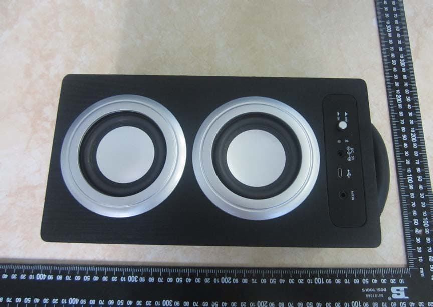
2AAFH-WM2899
Aug 30, 2014Bluetooth speaker
Equipment Class
DSS - Part 15 Spread Spectrum Transmitter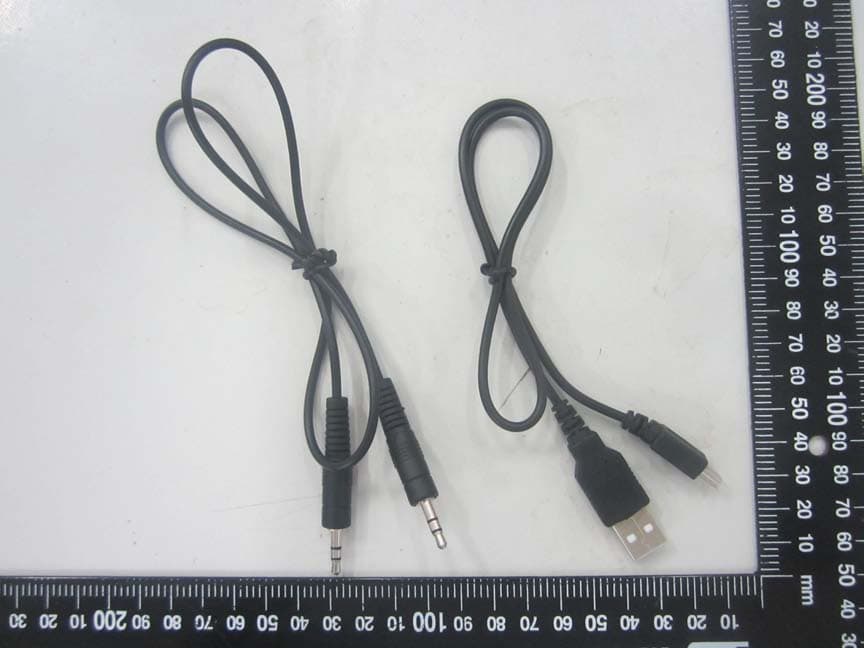
2AAFH-WO240
Aug 17, 2014Bluetooth speaker
Equipment Class
DSS - Part 15 Spread Spectrum Transmitter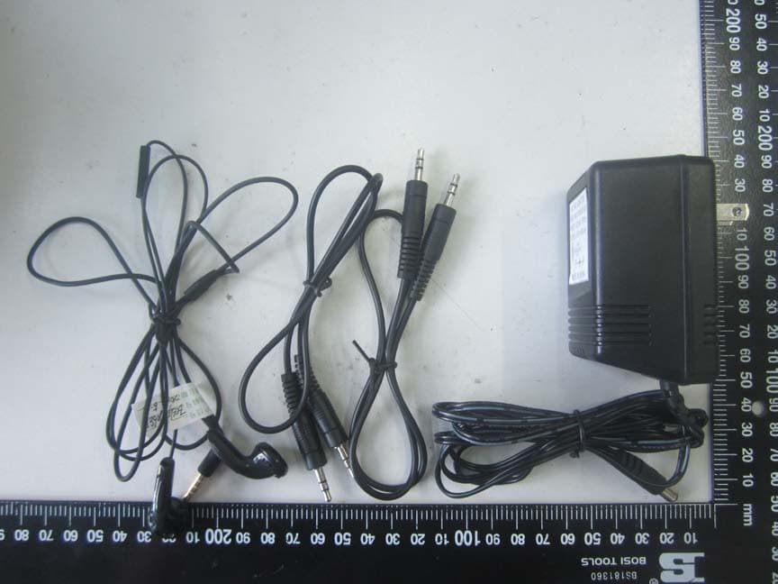
2AAFH-CD95BT
Jul 29, 2014CD Player
Equipment Class
DSS - Part 15 Spread Spectrum Transmitter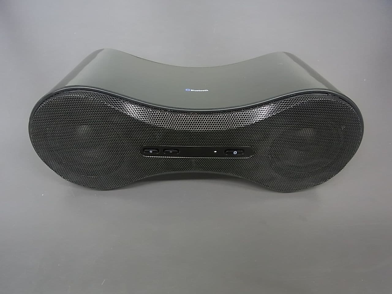
2AAFH-SPK90A
May 30, 2013BLUETOOTH SPEAKER
Equipment Class
DSS - Part 15 Spread Spectrum Transmitter