2AAJX-QS5210P01Wireless Carbon Monoxide Alarm
Qolsys, Inc.
Click to zoom
Application Details
- Equipment Class
- DSC - Part 15 Security/Remote Control Transmitter
- Date of Grant
- Sep 05, 2014
- Application Purpose
- Original Equipment
- Date of Application
- Sep 04, 2014
- Equipment Note
- Wireless Carbon Monoxide Alarm
- Frequency Range
- 319.50000000 - 319.50000000
- Company
- Qolsys, Inc.
- Country
- United States
Documents & Files
Document Text
Text extracted from the exhibit documents filed with the FCC. Open a document above to read the original.
Users Manual
IQCO (QS-5210-PO1) Wireless Carbon Monoxide Alarm Installation Guide Attention: This manual should be read prior to use and retained for further information. GENERAL INFORMATION The IQCO (QS-5210-PO1) Wireless Carbon Monoxide Alarm is a 3V battery powered wireless detector intended for use with a compatible wireless alarm system. The detector consists of an electrochemical carbon monoxide sensor assembly coupled to a wireless transmitter. The IQCO (QS-5210-PO1) Wireless Carbon Monoxide Alarm communicates with the control panel and can send alarm, tamper and battery condition messages to the system’s receiver. Refer to the wireless system’s instruction for the maximum number of transmitters that can be supported. IMPORTANT: This detector must be tested and maintained regularly following NFPA 720 requirements. This device is designed to protect individuals from the acute effects of carbon monoxide exposure. It will not fully safeguard individuals with specifi c medical conditions. If in doubt consult a medical practitioner. ÌWARNING This product is intended for use in ordinary indoor residential areas. It is not designed to measure compliance with Occupational Safety & Health Administration (OSHA) commercial and industrial standards. Contents of box: • IQCO (QS-5210-PO1) Wireless Carbon Monoxide Alarm with base • Installation guide • Pack of screws and anchors • Labels as appropriate • 1 CR123A Panasonic battery ! 2 APD0597 A140618 Qolsys IQCO (QS-5210-PO1) Wireless CO Install Guide The IQCO (QS-5210-PO1) Wireless Carbon Monoxide Alarm contains a sounder which generates the ANSI S3.41 temporal 4 pattern in an alarm condition (see Table 1 for temporal 4 pattern). In alarm, a message is also sent to the control panel and the detector’s ID is displayed at the console. During an alarm condition, pressing the detector’s hush button will silence the sounder for fi ve minutes. The mounting base installation is simplifi ed by the incorporation of features compatible for both drywall fasteners (not supplied) and other methods. Tricolored LED (green, yellow, red) and a sounder on the detector provide local visual and audible indication of the detector’s status as listed in Table 1. During initial power-up the LED blinks alternately green, yellow then red. It takes about 60 seconds for the detector’s CO sensor to stabilize. After power-up has completed and the detector is functioning normally, the green LED blinks once every 12 seconds. StatusLEDs Sounder (does not pulse the sounder and LED concurrently) Radio signalling Normal Green fl ash every 12 seconds Off Normal (None) Alarm/ Test Red fl ash every 12 seconds ANSI S3.41 temporal 4 (press button to hush for 5 minutes) Alarm Detector trouble Yellow fl ash every 6 seconds One 100ms chirp every 45 seconds Fault Low battery Yellow fl ash every 12 seconds One 100ms chirp every 45 seconds (press button to hush for 12 hours) Low Battery Detector end of life Yellow fl ash every 23 seconds One 100ms chirp every 45 seconds Fault Powerup Green, yellow, red fl ash sequence every 12 seconds One 100ms chirp at end of power- up sequence None Tamper Green, yellow, red fl ash sequence every 12 seconds OffTamper Table 1. Detector status and indication 22 APD0597 A140618 Qolsys IQCO (QS-5210-PO1) Wireless CO Install Guide REMARQUE: La date de remplacement fi gurant sur l’appareil est la date à partir de laquelle l’appareil risque de ne plus détecter correctement le monoxyde de carbone et à laquelle il doit donc être changé. ATTENTION SPECIFICATIONS • Source d’alimentation: Un 3 volts CR123A Panasonic Batterie au lithium (inclus) • Signal sonore (temp 4 de ton): 85 dBA min. en alarme (à 10 pieds (3 m)) • Courant de fonctionnement: 10 μ A • Température: 40 ° F (4,4 ° C) à 100 ° F (37,8 ° C) • Humidité en fonctionnement: 15% à 95% d’humidité relative, sans condensation • Attente Listes Agence: la norme UL 2075, UL 2034 et CSA 6.19-01 Qolsys 2011 Stevens Creek Blvd. Cupertino, CA 95014 www.qolsys.com 3 APD0597 A140618 Qolsys IQCO (QS-5210-PO1) Wireless CO Install Guide Detector Trouble: When the sensor supervision is in trouble condition, the yellow LED blinks once every six seconds and there is a chirp every 45 seconds. After 12 hours the panel will display a loss of supervision message. Detector end of life feature: When the detector has reached the end of its life, the yellow LED blinks once every 23 seconds and there is a chirp every 45 seconds. After 12 hours the panel will display a loss of supervision message. This indicates that the CO sensor inside the detector has passed the end of its life and the detector must be replaced. The detector lifespan is fi ve years from the date of manufacture. Refer to DETECTOR REPLACEMENT section. Low Battery Detection: The Wireless Carbon Monoxide Alarm is powered by a single 3-volt CR123A Panasonic Lithium battery (included). The detector regularly checks for a low battery. If a low battery is detected, the transmitter sends a low battery message to the control panel, which displays the detector’s ID at low battery. In addition, the yellow LED of the detector will blink every 12 seconds. The detector’s sounder will chirp every 45 seconds (yellow LED continues to blink) until the battery is replaced. Pressing the hush button will silence the chirps for 12 hours, if no other trouble conditions exist. The battery should be replaced WHEN the chirps begin. Be sure to replace the battery with a fresh one. Unauthorized changes or modifi cations could void the user’s authority to operate the equipment. BATTERY INSTALLATION AND REPLACEMENT To replace the battery: 1. Remove the detector from its mounting base by twisting the detector counterclockwise. Remove and dispose of the battery according to your local regulations. 2. 2. To ensure proper power-down sequence, wait a minimum of 20 seconds before installing new battery. 3. Install a new 3-volt CR123A Panasonic Lithium battery (available from your Panasonic dealer) in the battery com…
Text truncated - open the document above for the full version.
Cover Letter(s)
The University of Michigan Radiation Laboratory 3228 EECS Building Ann Arbor, Michigan 48109-2122 USA Tel: (734) 483-4211 Fax: (734) 647-2106 e-mail: [email protected] Re: Certification for Qolsys, Inc. FCC ID: 2AAJX-QS5210P01 IC: 11205A-QS5210P01 REQUEST FOR CONFIDENTIALITY Pursuant to USA FCC 47 CRF 0.457(d) and 0.459 and Canada IC RSP-100, Section 10, Qolsys, Inc.requests that a part of the subject application be held confidential. Qolsys, Inc. has spent substantial effort in developing this product and it is one of the first of its kind in industry. Having the subject information easily available to ”competition” would negate the advantage they have achieved by developing this product. Not protecting the details of the design will result in financial hardship. Exhibit Conf. TypeRational Exh 04 - Block DiagramPermanentIncludes proprietary internal oscillator frequency information. Exh 05 - SchematicsPermanentIncludes proprietary design information Exh 10 - BOM + PlacementPermanentIncludes proprietary design information Permanent Confidentiality:Qolsys, Inc. requests that any exhibits listed above as permanently confidential be permanently withheld from public review. Short-Term Confidentiality (FCC Only):Qolsys, Inc. requests that any exhibits selected above as short term confidential be withheld from public view for a period of 45 days from the date of the Grant of Equipment Authorization and prior to marketing. If there are any questions regarding the application or testing performed, please contact us at the above address or call (734) 483-4211, or e-mail [email protected]. Sincerely, Valdis V. Liepa The University of Michigan Radiation Laboratory 10
Cover Letter(s)
The University of Michigan Radiation Laboratory 3228 EECS Building Ann Arbor, Michigan 48109-2122 USA Tel: (734) 483-4211 Fax: (734) 647-2106 e-mail: [email protected] Attn.:Certification and Engineering Bureau Industry Canada 3701 Carling Avenue, Bldg. 94 Ottawa, Ontario K2H 8S2 Re: Certification for Qolsys, Inc. QS-5210-PO1 IC: 11205A-QS5210P01 Please find enclosed application materials for certification of Qolsys, Inc. QS-5210-PO1. We tested it and found it to comply with IC RSS-210/GENe. Current Variants: There is only a single variant of the EUT, as tested. If there are any questions regarding the application or testing performed, please contact us at the above address or call (734) 483-4211, or e-mail [email protected]. Sincerely, Valdis V. Liepa The University of Michigan Radiation Laboratory 12 The University of Michigan Radiation Laboratory 3228 EECS Building Ann Arbor, Michigan 48109-2122 USA Tel: (734) 483-4211 Fax: (734) 647-2106 e-mail: [email protected] Attn.:Federal Communications Commission Equipment Approval Services P.O. Box 358315 Pittsburgh, PA 15251-5315 Re: Certification for Qolsys, Inc. QS-5210-PO1 FCC ID: 2AAJX-QS5210P01 Please find enclosed application materials for certification of Qolsys, Inc. QS-5210-PO1. We tested it and found it to comply with CFR Title 47, Part 15.231. If there are any questions regarding the application or testing performed, please contact us at the above address or call (734) 483-4211, or e-mail [email protected]. Sincerely, Valdis V. Liepa The University of Michigan Radiation Laboratory 11
ID Label/Location Info
1 IMPRINT ART IS NOT FINAL SHEET 2 OF 2 10/11/2013 10/12/2013 AF JRB UNLESS OTHERWISE SPECIFIED: SCALE: 1:1 DWG. NO. A TITLE: NAMEDATE COMMENTS: MFG APPR. ENG APPR. CHECKED DRAWN PROPRIETARY AND CONFIDENTIAL THE INFORMATION CONTAINED IN THIS DRAWING IS THE SOLE PROPERTY OF APOLLO AMERICA, INC.. ANY REPRODUCTION IN PART OR AS A WHOLE WITHOUT THE WRITTEN PERMISSION OF APOLLO AMERICA, INC. IS PROHIBITED. 5 4 3 2 1 SIZE REV DRAWING IS FOR REFERENCE ONLY...CAD IS MASTER WIRELESS CARBON MONOXIDE ALARM ALARME SANS FIL DE DÈTECTION DU MONOXYDE DE CARBONE QS-5210-P01 / IQCO REFER TO INSTALL GUIDE/SE RÉFÉRER A GUIDE D'INSTALLATION: APD0595 THESE SHOULD BE READ AND RETAINED/VEUILLEZ LIRE CE MANUEL AVANT UTILISATION ET CONSERVÉS-LE COMME RÉFÉRENCE ULTÉRIEURE WARNING AVERTISSEMENT CARBON MONOXIDE CANNOT BE SEEN OR SMELLED BUT CAN KILL YOU. IF ALARM SIGNAL SOUNDS: 1) OPERATE TEST/HUSH BUTTON. 2) CALL YOUR EMERGENCY SERVICES (FIRE DEPARTMENT OR 911). 3) IMMEDIATELY MOVE TO FRESH AIR - OUTDOORS OR BY AN OPEN DOOR/WINDOW. LE MONOXYDE DE CARBONE EST INVISIBLE ET SANS ODEUR MAIS PEUT ÊTRE FATAL. EN CAS DE DÉCLENCHEMENT DE L ‘ALARME: 1) APPUYER SUR LE BOUTON DE REMISE A TEST/HUSH. 2) COMPOSEZ LE NUMÉRO D’URGENCE (POMPIERS DU 911). 3) PRENEZ IMMÉDIATEMENT L’ AIR - A L ‘EXTERIEUR OU A UNE FENÊTRE. USE ONLY BATTERIES SPECIFIED IN MARKING. USE OF A DIFFERENT BATTERY WILL HAVE A DETRIMENTAL EFFECT ON DEVICE OPERATION. UTILISEZ LES PILES RECOMMANDÉES UNIQUEMENT DANS LE GUIDE D’INSTALLATION. L ‘UTILISATION DE PILES DIFFERENTES POURRAIT NUIRE AU BON FONCTIONNEMENT DE L ’APPEREIL. REPLACEMENT BATTERY TYPE / CHANGEMENT DE LA PILE: PANASONIC CR123A CONSTANT EXPOSURES TO HIGH OR LOW TEMPS OR HIGH HUMIDITY MAY REDUCE BATTERY LIFE / DES EXPOSITIONS CONSTANTES A DES TEMPERATURES ELEVES OU BASSES OU A UNE HUMIDITE ELEVEE PEUVENT REDUIRE L'AUTONOMIE DES PILES SENSITIVITY/SENSIBILITÉ: 400PPM, RESPONSE TIME/TEMPS DE REPONSE: 4-15 MINUTES • CLEAN WITH DRY CLOTH • TEST ONCE A WEEK BY PUSHING TEST/HUSH BUTTON • RETURN TO QOLSYS FOR SERVICING • EXAMINEZ UNE FOIS PARE SEMAINE EN POUSSANT LE BOUTON DE TEST/HUSH • NETTOYER AVEC UN CHIFFON • REVENEZ A QOLSYS POUR L'ENTRETIEN 20111 STEVENS CREEK ROAD CUPERTINO, CA 95014 www.QOLSYS.com 1234567 FCC ID: 2AAJX-QS5210P01 IC: 11205A-QS5210P01 FREQUENCY: 319.5MHz Model: QS-5210-P01 MANUFACTURED BY/FABRIQUEE PAR APOLLO: 25 CORPORATE DRIVE, AUBURN HILLS MI 48326 MADE IN USA
ID Label/Location Info
Apollo America, Inc. 25 Corporate DriveTel: +1 (248) 332-3900Email:[email protected] Auburn Hills, MI 48326 USA Fax: +1 (248) 332-8807Web: www.apollo-fire.com To whom it may concern, In regards to the labeling requirements found in CFR 47, Part 15.19, the project being filed with the FCC does not have sufficient room, due to the safety marking requirements of UL 217, CAN/ULC-S531, UL 2034, and CAN/CSA-6.19. A nearly identical filing has been performed in the past under Apollo Fire Detectors, LTD. FCC ID numbersZFH-CO3345 and ZFH-SMKT3345. I believe that the subpart (5) of part 15.19 (See excerpt below) was used with the original filing: (5) When the device is so small or for such use that it is not practicable to place the statement specified under paragraph (a) of this section on it, the information required by this paragraph shall be placed in a prominent location in the instruction manual or pamphlet supplied to the user or, alternatively, shall be placed on the container in which the device is marketed. However, the FCC identifier or the unique identifier, as appropriate, must be displayed on the device. If you have any other questionsor concerns regarding this, or any other matter, please do not hesitate in contacting me. Best regards, John Schertel Conformance Manager
Operational Description
Radio sub-system (Radio partner to provide) The wireless sub-system will be designed by a 3rd party radio partner and supplied to Apollo fully tested ready for installation into the product. The Radio sub-system will include the aerial and radio transmitter such that it complies with the PCB outline below. The radio sub-system will also include the radio signalling protocol compatible with the partner’s wireless residential security system. The status of the detector will be read from the interface at regular intervals to ensure that transmissions to the panel comply with the required response times. To minimise the possibility of an interconnect failure going unmonitored the input side should endeavour to use switched pull-ups from time to time to confirm that the active pin state is being read. Specifications Voltage 2.0V to 3.6V Ripple voltage 200mV Maximum standby current 1μA Maximum average current 20 μA Maximum transmit current 50mA Power-up delay 1s maximum before 1 st transmission Power-up sequence Header allowed to be in any state Alarm signalling delay 1s maximum Manufacturing testing Low power mode for test equipment Manufacturing label printing PC based RF unit to read the ID number Signalling rules Single (prioritised) state signalled Disable Radio Command Radio comms disabled for Apollo soak Radio range > 450ft Pin 7 synchronisation 4 second heartbeat in quiescent state Header connections Pin No. Connection Direction Signal 1 0V Apollo to Radio PCB Battery negative terminal 2 3V Apollo to Radio PCB Battery positive terminal 3 Alarm Apollo to Radio PCB 0=good, 1=alarm decode If Alarm and fault are both high then radio 4 Fault Apollo to Radio PCB 0=good, 1=fault decode comms are disabled until one or both pin(s) go low 5 Alarm and Fault Decode 0 Apollo to Radio PCB AFD 0 0 0 1 1 AFD 1 0 1 0 1 Alarm Smoke Heat Freeze Test Fault General Battery Tamper Sens’vity 6 Alarm and Fault Decode 1 Apollo to Radio PCB 7 Device Active Apollo to Radio PCB 0=no activity 1=sounder or smoke sampling active 8 Activate Sounder Radio PCB to Apollo 0=normal operation 1=activate sounder/LED The detector status is signalled through an 8 wire interface, power (2) and status flags (4). This will be in the form of an 8 way in line header. The device active pin can be used to monitor the detector PCB. During normal operation the detector will be sampling every 4 seconds. It is important that the radio system does not draw more than the average quiescent current during the device active periods because the source impedance of the batteries will cause a significant voltage drop. The 3V supply will be running from storage during the sounder active periods and excessive current draw will collapse the supply. If the detector status is fire, fault or activate sounder the sounder activations must be avoided. I the case of fire/CO alarm or sounder on the active sounder signalling will commence after one full temporal synchronisation cycle. For this cycle the fire pin will be low, the decode pins will indicate the event and the device active pin will be low during the sounder activation periods but the sounder will be off. The second cycle of the temporal pattern the sounder will be on during the sounder activation periods. This gives the radio system 4 seconds warning of the impending lockout which allows it to re-sync itself to avoid any clashes. If the detector status is fault the single fault chirp warning will be given 4 seconds before the fault chirping commences. Truth table for the header pin decode Pin 3 Pin 4 Pin 5 Pin 6 Status Priority 0 0 0 0 Normal 10 0 0 ? ? Pin 5 and pin 6 must be low if pin 3 and pin 4 are low 1 0 0 0 Smoke alarm 2 1 0 0 1 Heat alarm 3 1 0 1 0 Freeze alarm 4 1 0 1 1 Test button active 1 0 1 0 0 General fault 5 0 1 0 1 Battery low 6 0 1 1 0 Tamper fault 8 0 1 1 1 Dirty detector 7 1 1 X X Radio signalling off 9 Radio sub-system PCB outline The outer edge of the PCB (the 47.50mm radius) has a 2mm no-go area for components around the complete arc. The pins should be a standard 0.1” pitch 0.5” long square pin gold flash finish header. The PCB has 5mm clearance on the top side and 10mm clearance on the far side (as shown below). The RF power reduction pad should reduce the radiated signalling power of the radio PCB to allow Manufacturing to check the alarm signalling at final test without corrupting other test stations. All areas shown hatched are to be free of components.
Test Report
Date of Issue: August 3, 2014Prepared For: Qolsys, Inc.Test Report No.: 417124-675r1 The University of Michigan Radiation Laboratory 3228 EECS Building Ann Arbor, Michigan 48109-2122 USA Tel: (734) 483-4211 Fax: (734) 647-2106 e-mail: [email protected] Testing of Electromagnetic Emissions per USA: CFR Title 47, Part 15.231 Canada: IC RSS-210/GENe are herein reported for Qolsys, Inc. QS-5210-P01 Test Report No.: 417124-675r1 Copyright c ©2014 Applicant/Provider: Qolsys, Inc. 20111 Stevens Creek Blvd., Suite 280, Cupertino California 95014 USA Phone: 408-857-8415, Fax: 408-927-5832 Contact Person: Mark Skeen; [email protected] Report by: Report Date of Issue: August 3, 2014 Valdis V. Liepa, Ph.D. Results of testing completed on (or before) July 17, 2014 are as follows. Emissions:The transmitter intentional emissionsCOMPLYwith the regulatory limit(s) by no less than 1.4 dB. Transmit chain spurious harmonic emissionsCOMPLYby no less than 3.9 dB. Unintentional spurious emissions from digital circuitryCOMPLYwith radiated emission limit(s) by more than 20 dB. The University of Michigan Radiation Laboratory, 3228 EECS Building, Ann Arbor, Michigan 48109-2122 USAPage 1 of 15 Date of Issue: August 3, 2014Prepared For: Qolsys, Inc.Test Report No.: 417124-675r1 Contents 1 Test Specifications, General Procedures, and Location3 1.1 Test Specification and General Procedures . . . . . . . . . . . . . . . . . . . . . . . . . . . . . . . . . .3 1.2 Test Location and Equipment Used . . . . . . . . . . . . . . . . . . . . . . . . . . . . . . . . . . . . . .4 2 Configuration and Identification of the Equipment Under Test5 2.1 Description and Declarations . . . . . . . . . . . . . . . . . . . . . . . . . . . . . . . . . . . . . . . . .5 2.1.1EUT Configuration . . . . . . . . . . . . . . . . . . . . . . . . . . . . . . . . . . . . . . . . . . .5 2.1.2Modes of Operation . . . . . . . . . . . . . . . . . . . . . . . . . . . . . . . . . . . . . . . . . .5 2.1.3Variants . . . . . . . . . . . . . . . . . . . . . . . . . . . . . . . . . . . . . . . . . . . . . . . . .6 2.1.4Test Samples . . . . . . . . . . . . . . . . . . . . . . . . . . . . . . . . . . . . . . . . . . . . . .6 2.1.5Functional Exerciser . . . . . . . . . . . . . . . . . . . . . . . . . . . . . . . . . . . . . . . . . .6 2.1.6Modifications Made . . . . . . . . . . . . . . . . . . . . . . . . . . . . . . . . . . . . . . . . . .6 2.1.7Production Intent . . . . . . . . . . . . . . . . . . . . . . . . . . . . . . . . . . . . . . . . . . .6 2.1.8Declared Exemptions and Additional Product Notes . . . . . . . . . . . . . . . . . . . . . . . .6 3 Emissions7 3.1 General Test Procedures . . . . . . . . . . . . . . . . . . . . . . . . . . . . . . . . . . . . . . . . . . . .7 3.1.1Radiated Test Setup and Procedures . . . . . . . . . . . . . . . . . . . . . . . . . . . . . . . . .7 3.1.2Conducted Emissions Test Setup and Procedures . . . . . . . . . . . . . . . . . . . . . . . . . .9 3.1.3Power Supply Variation . . . . . . . . . . . . . . . . . . . . . . . . . . . . . . . . . . . . . . . .9 3.2 Intentional Emissions . . . . . . . . . . . . . . . . . . . . . . . . . . . . . . . . . . . . . . . . . . . . . . 10 3.2.1Fundamental Emission Pulsed Operation . . . . . . . . . . . . . . . . . . . . . . . . . . . . . . 10 3.2.2Fundamental Emission Bandwidth . . . . . . . . . . . . . . . . . . . . . . . . . . . . . . . . . . 12 3.2.3Fundamental Emission . . . . . . . . . . . . . . . . . . . . . . . . . . . . . . . . . . . . . . . . . 13 3.3 Unintentional Emissions . . . . . . . . . . . . . . . . . . . . . . . . . . . . . . . . . . . . . . . . . . . . 14 3.3.1Transmit Chain Spurious Emissions . . . . . . . . . . . . . . . . . . . . . . . . . . . . . . . . . 14 3.3.2Radiated Digital Spurious . . . . . . . . . . . . . . . . . . . . . . . . . . . . . . . . . . . . . . . 15 List of Tables 1The University of Michigan Radiation Laboratory Equipment List.. . . . . . . . . . . . . . . . . . .4 2EUT Declarations. . . . . . . . . . . . . . . . . . . . . . . . . . . . . . . . . . . . . . . . . . . . . . . .5 3Pulsed Emission Characteristics (Duty Cycle). . . . . . . . . . . . . . . . . . . . . . . . . . . . . . . . 10 4Intentional Emission Bandwidth.. . . . . . . . . . . . . . . . . . . . . . . . . . . . . . . . . . . . . . 12 5Fundamental Radiated Emissions. . . . . . . . . . . . . . . . . . . . . . . . . . . . . . . . . . . . . . . 13 6Transmit Chain Spurious Emissions. . . . . . . . . . . . . . . . . . . . . . . . . . . . . . . . . . . . . . 14 List of Figures 1Photos of EUT.. . . . . . . . . . . . . . . . . . . . . . . . . . . . . . . . . . . . . . . . . . . . . . . .5 2EUT Test Configuration Diagram. . . . . . . . . . . . . . . . . . . . . . . . . . . . . . . . . . . . . . .6 3Radiated Emissions Diagram of the EUT. . . . . . . . . . . . . . . . . . . . . . . . . . . . . . . . . . .7 4Radiated Emissions Test Setup Photograph(s). . . . . . . . . . . . . . . . . . . . . . . . . . . . . . . .8 5Pulsed Emission Characteristics (Duty Cycle). . . . . . . . . . . . . . . . . . . . . . . . . . . . . . . . 11 6Intentional Emission Bandwidth.. . . . . . . . . . . . . . . . . . . . . . . . . . . . . . . . . . . . . . 12 The University of Michigan Radiation Laboratory, 3228 EECS Building, Ann Arbor, Michigan 48109-2122 USAPage 2 of 15 Date of Issue: August 3, 2014Prepared For: Qolsys, Inc.Test Report No.: 417124-675r1 1 Test Specifications, General Procedures, and Location 1.1 Test Specification and General Procedures The ultimate goal of Qolsys, Inc. is to demonstrate that the Equipment Under Test (EUT) complies with the Rules and/or Directives below. Detailed in this report are the results of testing the Qolsys, Inc. QS-5210-P01 for compliance to: Country/RegionRules or DirectiveReferenced Section(s) United StatesCode of Federal RegulationsCFR Title 47, Part 15.231 CanadaIndustry CanadaIC RSS-210/GENe In association with the rules and directives outlined above, the following specification…
Text truncated - open the document above for the full version.
Contact Information
Applicant
Mark Skeen(VP Business Development, Global Products)
Technical Contact
The University of Michigan Radiation LaboratoryValdis V Liepa
[email protected]734 483 4211
3228 EECS Building · Ann Arbor, Michigan · United States
Test Firm
University of MichiganValdis Liepa
Technical Specifications
| # | Rule Parts | Frequency Range | Power Output |
|---|---|---|---|
| 1 | 15.231 | 319.5 MHz - 319.5 MHz | - |
Other Applications from Qolsys, Inc.
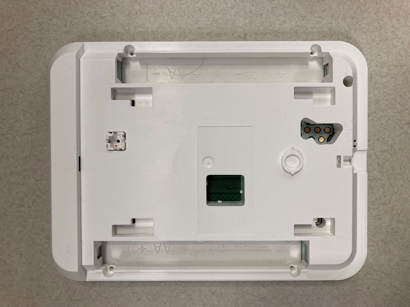
2AAJXQS-IQKP
Aug 19, 2023PowerG Wirefree Keypad with prox
Equipment Class
DSS - Part 15 Spread Spectrum Transmitter
2AAJXQS-IQDWM
Aug 03, 2023Door Sensor Alarm System
Equipment Class
DSC - Part 15 Security/Remote Control Transmitter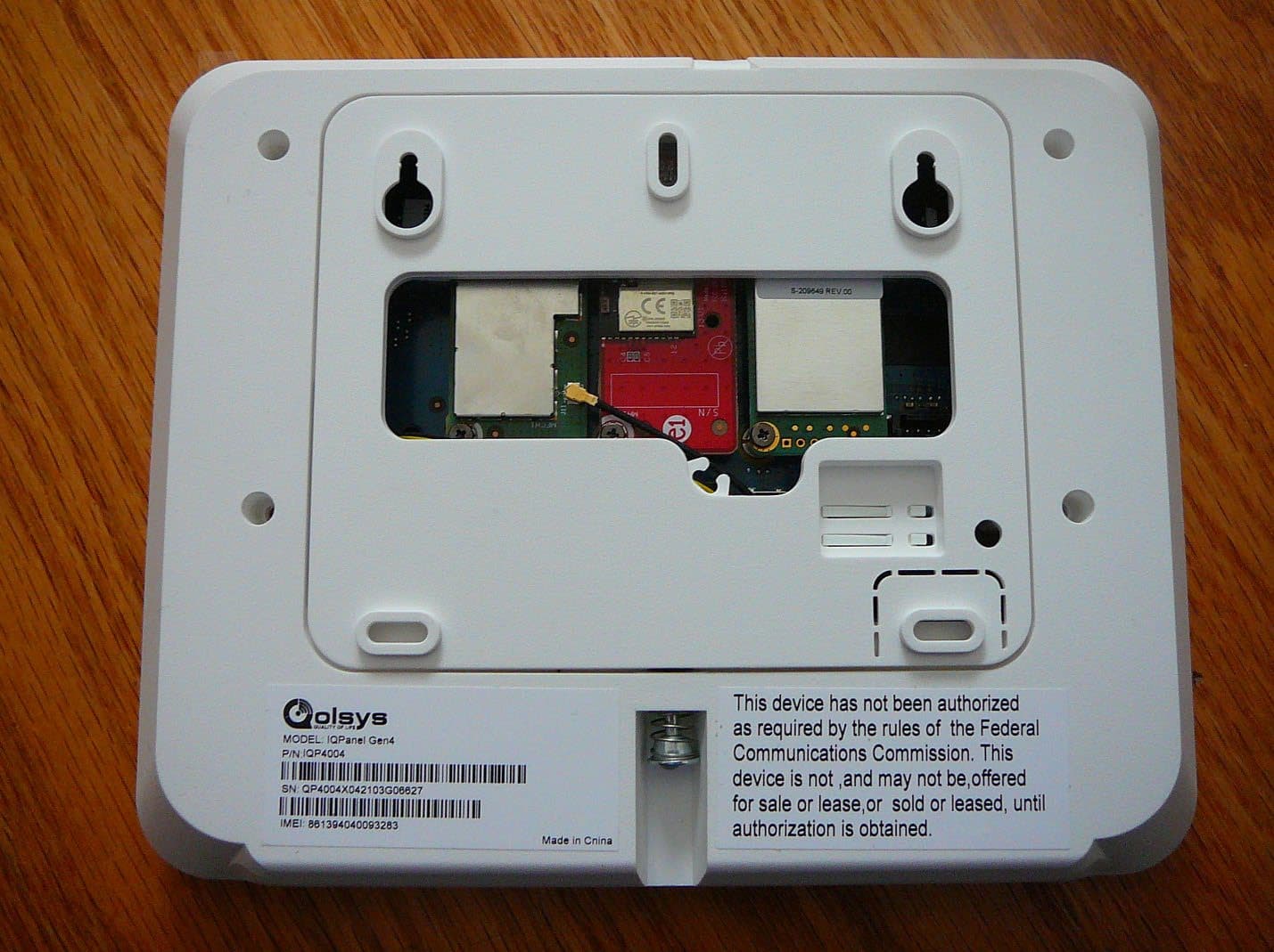
2AAJXQS-IQP4Z
Feb 27, 2023Zwave 800 Radio
Equipment Class
DXX - Part 15 Low Power Communication Device Transmitter
2AAJXQS-IQWIFI6
Aug 25, 2021IQ WiFi 6
Equipment Class
DTS - Digital Transmission System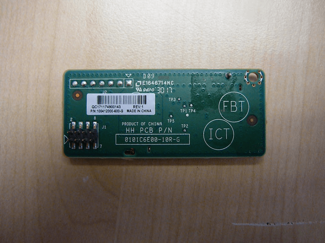
2AAJXQS-ZWAVEAH
Oct 29, 2020Zwave Module
Equipment Class
DXT - Part 15 Low Power Transceiver, Rx Verified