2AAJXQS1100wireless door/window sensor to be used in the Qolsys IQ home security system
Qolsys, Inc.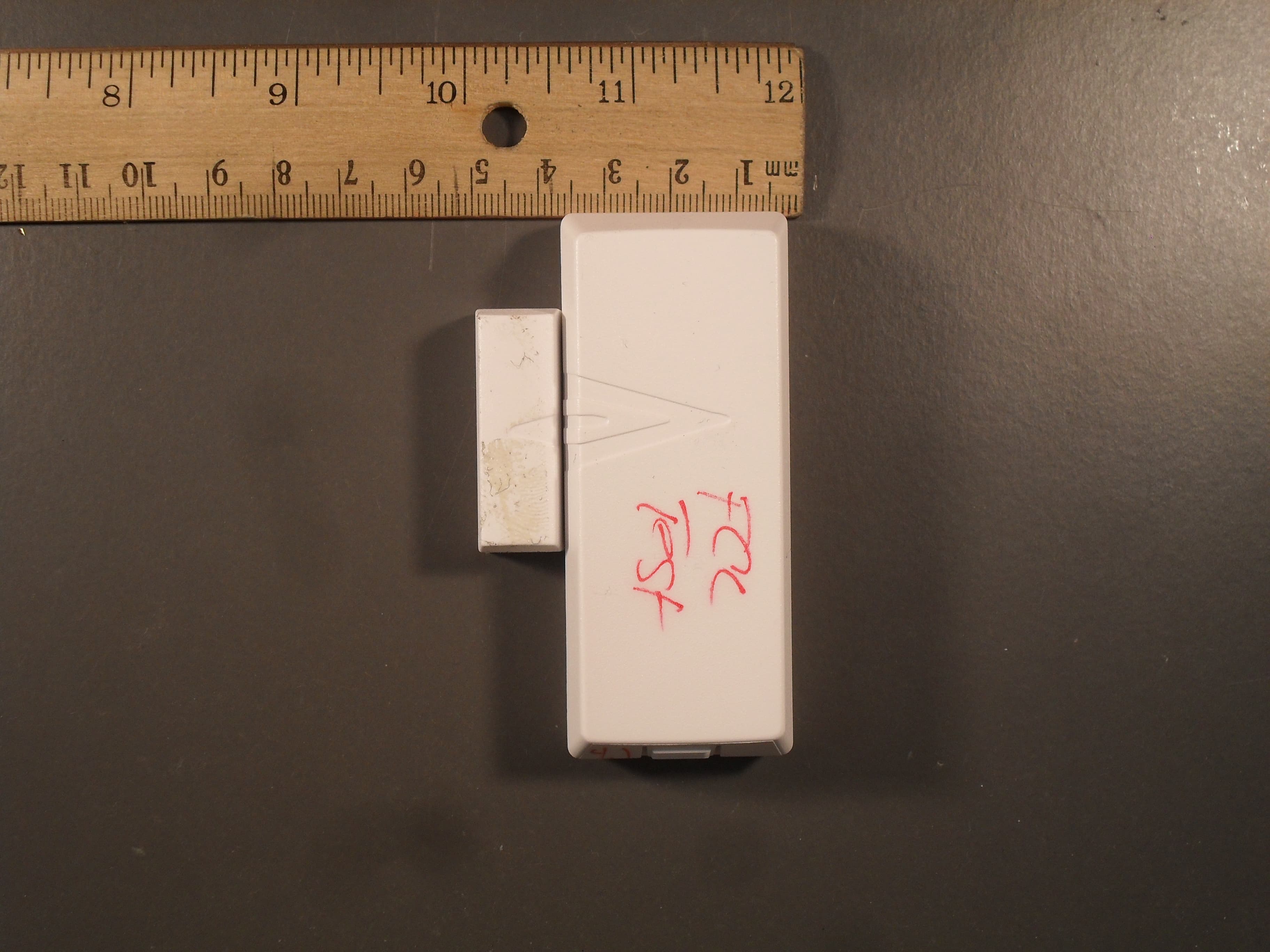
Click to zoom
Application Details
- Equipment Class
- DSC - Part 15 Security/Remote Control Transmitter
- Date of Grant
- Aug 23, 2015
- Application Purpose
- Original Equipment
- Date of Application
- Aug 23, 2015
- Equipment Note
- wireless door/window sensor to be used in the Qolsys IQ home security system
- Frequency Range
- 319.50000000 - 319.50000000
- Company
- Qolsys, Inc.
- Country
- United States
Documents & Files
Document Text
Text extracted from the exhibit documents filed with the FCC. Open a document above to read the original.
Users Manual
IQ DOOR/WINDOW- INSTALLATION MANUAL QOLSYS CONFIDENTIAL AND PROPRIETARY PAGE 1 OF 6 © Last revised 2/27/15 All rights reserved The Qolsys IQ Door/Window is a sleek, high- performance wireless sensor that detects opening and closing of doors, windows and anything else which opens and closes (drawers, cabinets, etc). It works seamlessly with the Qolsys IQPanel. 1 Door/Window Sensor 1 Magnet 6 screws 1 large strip of double sided adhesive 1 small strip of double sided adhesive PRODUCT FEATURES PARTS INCLUDED IQ DOOR/WINDOW Wireless signal range: 600ft (200M),open air. Code outputs: tamper, tamper restore, alarm (primary open), alarm restore (primary close), external alarm (secondary wired open), external restore (secondary wired closed), low battery. Transmitter frequency : 319.5MHZ Unique code ID Supervisory keep-alive interval: 70 minutes. RF output power 91.1dBuV +/- 5% at 3m TECHNICAL SPECIFICATIONS •Low profile •Supports one or two doors, windows, etc. •Primary wireless magnet contact and secondary wired contact •Internal or external reed switch •Easy, wire-free installation •Secondary (optional) sensor (external wired Door/Window sensor) •Advanced circuit technology resulting in ultra-low power consumption •Easy to install Batteries •Over 5 years of battery life •Tamper Detection •Supervisory health messaging •Sensor Open and Close detection 6 IQ DOOR/WINDOW- INSTALLATION MANUAL QOLSYS CONFIDENTIAL AND PROPRIETARY PAGE 2 OF 6 © Last revised 2/27/15 All rights reserved •Mount the sensor on the door frame and the magnet on the door. If the sensor is used on double doors, mount the sensor on the least-‐used door and the magnet on the most-‐used door. •If possible, locate sensors within 100 ft. (30 m) from the panel. •While a transmiAer may have a range of 600 E. (200 m) or more out in the open, the environment at the installation site can have a significant effect on transmitter range. Some-‐ Jmes a change in sensor orientaJon can help overcome adverse wireless condiJons. •Make sure the alignment arrow on the magnet points to the alignment mark on the sensor. •Place sensors at least 6 in. (15.24 cm) above the floor to avoid damaging them. •Avoid mounJng sensors in areas where they will be exposed to moisture or where the sensor operating temperature range of 0 to 120°F (0 to 49°C) will be exceeded. •Use spacers (not included) to keep sensors and magnets away from metal or metallic surfaces such as foil wallpaper. •Avoid mounting sensors in areas with a large quantity of metal or electrical wiring, such as a furnace or uJlity room GUIDELINES Be sure to align the triangle guides on the sensor and magnet as shown. This will enable the proper contact between the sensor and magnet. When closed, the magnet should be within .4” of the sensor for optimum sensitivity. PLACEMENT AND SPACING BATTERY ACTIVATION To activate the batteries in the sensor, remove the cover and pull out the plastic tabs between the batteries and the contacts. Please note: the sensor will not operate the reed switch and external contact header simultaneously. Tamper switch External contact header BaAery retenJon clips IQ DOOR/WINDOW- INSTALLATION MANUAL QOLSYS CONFIDENTIAL AND PROPRIETARY PAGE 3 OF 6 © Last revised 2/27/15 All rights reserved MOUNTING WITH PROVIDED ADHESIVE •Remove the back of the sensor by pressing on the tab and pulling the cover off •Place the base of the sensor on the appropriate surface and use 4 of the supplied screws to secure the mounJng plate to the chosen locaJon •To secure the magnet, remove the mounJng plate by prying it off the magnet casing. •Be sure the arrows on the top of the casing align with the arrows on the sensor casing. The sensor and magnet should not be mounted more than 0.4 inches apart. •Use the 2 remaining screws provided to secure the magnet mounJng plate in the proper locaJon. Clip the magnet casing back into place once the plate is secure. MOUNTING WITH PROVIDED HARDWARE Push to remove sensor cover •Remove backing on one side of the large double-‐sided tape and sJck the exposed side on the back of the sensor as shown. •Remove the other side of the large double-‐sided tape and mount the device according to the installaJon instrucJons •Remove the backing one side of the small double-‐sided tape and place on back of magnet •Lineup the magnet with the sensor using the arrows shown on each device respecJvely. Ensure the sensor and magnet are not separated more than 0.4 inches as shown. •Remove the second side of the double-‐sided tape and secure the magnet. IQ DOOR/WINDOW- INSTALLATION MANUAL QOLSYS CONFIDENTIAL AND PROPRIETARY PAGE 4 OF 6 © Last revised 2/27/15 All rights reserved PROGRAMMING THE IQ DOOR/WINDOW The following steps describe general guidelines for programming (learning) the sensor into the IQ Panel. Refer to the IQ Panel's installation instructions for complete programming details. From the home screen of the IQ panel, touch the “Settings” icon Enter the installer passcode. Default installer passcode is 111112 Touch the “Installation” appTouch the “Security Sensors” app 34 Touch the “AutoLearn Sensor” app Tamper the sensor by pressing the tab and liEing off the cover. 54 A chime will sound Touch “Ok” 67 8 Check the auto-populated fields to ensure accuracy. Customize device settings as desired. 9 Create custom names by selecting “Sensor name” and choosing “Custom description.” A keyboard will appear, allowing you to type the name of your choice into the field. 10 Click “Add” to complete the process IQ DOOR/WINDOW- INSTALLATION MANUAL BATTERY REPLACEMENT To replace batteries: • Push tab on side of sensor and lift off cover. • Place fingernail or small screwdriver under the battery and gently lift up. The battery should release easily. Remove old battery. Replace with a new battery by putting one end under the golden battery retention clip. Gently push toward the opposite side until the the battery snaps into place under the black plastic. • Repeat this process…
Text truncated - open the document above for the full version.
ID Label/Location Info
Note: 1. Font size: 1.5mm Scale :1:1, unit :mm SN: QSCX12WW00001 Model: IQDWSensor P/N: QS-1100-P01 Tx ID ABCDEF DLEFCDAB FCC ID: 2AAJXQS1100 IC: 11205A-QS1100 09/2013 This device complies with Part 15 of the FCC rules. Operation is subject to the following conditions: (1) This device may not cause harmful interference and (2) this device must accept any int erference received, including interference that may cause undesired operation. Replace Battery with CR2032 3V Lit him cell ONLY. See User’s Manual for safety instructions Made in China Conforms to ANSI/UL Std 634 Certified to ULC Sub C634 4009595
ID Label/Location Info
Label Location
Test Report
This report is for the exclusive use of Intertek's Client and is provided pursuant to the agreement between Intertek and its Client. Intertek's responsibility and liability are limited to the terms and conditions of the agreement. Intertek assumes no liability to any party, other than to the Client in accordance with the agreement, for any loss, expense or damage occasioned by the use of this report. Only the Client is authorized to permit copying or distribution of this report and then only in its entirety. Any use of the Intertek name or one of its marks for the sale or advertisement of the tested material, product or service must first be approved in writing by Intertek. The observations and test results in this report are relevant only to the sample tested. This report by itself does not imply that the material, product, or service is or has ever been under an Intertek certification program. Non-Specific EMC Report Shell Rev. July 2013 Page 1 of 24 Qolsys Inc. IQDWSensor EMC TEST REPORT Report Number: 101052328ATL-007B Project Number: G10152328 Report Issue Date: November 25, 2014 Report Revised Date: April 9, 2015 Product Designation: IQDWSensor, QS1100 Standards: 47 CFR Part 15 Subpart C:2014 Section 15.231 RSS-210 Issue 8, 2010 Tested by: Client: Intertek Testing Services NA, Inc. 1950 Evergreen Blvd, Suite 100 Duluth, GA 30096 USA Qolsys Inc. 1900 The Alameda, Suite 420 San Jose, CA. 95126 USA Report prepared by Report reviewed by Mary Sampson/Senior Project Engineer Krishna Vemuri/Senior Staff Engineer Intertek Report Number: 101052328ATL-007B Issued: 04/09/2015 Non-Specific EMC Report Shell Rev. July 2013 Page 2 of 24 Qolsys Inc. IQDWSensor 1 Introduction and Conclusion The tests indicated in section 2.0 were performed on the product constructed as described in section 4.0. The remaining test sections are the verbatim text from the actual data sheets used during the investigation. These test sections include the test name, the specified test Method, a list of the actual Test Equipment Used, documentation Photos, Results and raw Data. No additions, deviations, or exclusions have been made from the standard(s) unless specifically noted. Based on the results of our investigation, we have concluded the product tested complies with the requirements of the standard(s) indicated. The results obtained in this test report pertain only to the item(s) tested. 2 Test Summary Section Test full name Result 3 Client Information 4 Description of Equipment Under Test 5 System Setup and Method 6 Restrictions (47 CFR Part 15 Subpart C:2014 Section 15.231(a)(2) RSS-210 Issue 8, 2010, Section A1.1.1(b)) Pass - AC Mains Conducted Emissions (Battery operated device) N/A 7 Fundamental Emissions (47 CFR Part 15 Subpart C:2014 Section 15.231(b) RSS-210 Issue 8, 2010, Section A1.1.2) Pass 8 Radiated Spurious Emissions below 1GHz (47 CFR Part 15 Subpart C:2014 Section 15.231(b) RSS-210 Issue 8, 2010, Section A1.1.2) Pass 9 Radiated Spurious Emissions Above 1 GHz (47 CFR Part 15 Subpart C:2014 Section 15.231(b) RSS-210 Issue 8, 2010, Section A1.1.2) Pass 10 Bandwidth (47 CFR Part 15 Subpart C:2014 Section 15.231(c) RSS-210 Issue 8, 2010, Section A1.1.3) Pass 11 Duty Cycle (47 CFR Part 15 Subpart C:2014 Section 15.35(c) RSS-GEN Issue 3, 2010, Section 4.5) Pass 12 RF Exposure Compliance (47 CFR Part 2 Subpart J: 2014 Section 2.1091) Pass 13 Revision History Intertek Report Number: 101052328ATL-007B Issued: 04/09/2015 Non-Specific EMC Report Shell Rev. July 2013 Page 3 of 24 Qolsys Inc. IQDWSensor 3 Client Information This EUT was tested at the request of: Client: Qolsys Inc. 1900 The Alameda, Suite 420 San Jose, CA. 95126 USA Contact: Mark Skeen Telephone: 408-857-8415 Fax: 408-927-5832 Email: [email protected] 4 Description of Equipment Under Test Manufacturer: Qolsys Inc. 1 900 The Alameda, Suite 420 San Jose, CA. 95126 USA Equipment Under Test Description Manufacturer Model Number Serial Number Wireless Door Window Sensor Qolsys Inc IQDWSensor QSCB134100300 Wireless Door Window Sensor Qolsys Inc IQDWSensor QSCB134700503 Receive Date: 10/16/2014 Received Condition: Good Type: Production Description of Equipment Under Test (provided by client) The IQDW Sensor is door/window wireless sensor to be used in the Qolsys IQ home security system. Equipment Under Test Power Configuration Rated Voltage Rated Current Rated Frequency Number of Phases 2.2 to 3 Vdc 30 μA N/A N/A Operating modes of the EUT: No. Descriptions of EUT Exercising 1 Continuous Transmission is a special test mode used only for simplifying the compliance testing process. This will never be activated by the end user. 2 Normal mode is transmission upon sensor activation or at supervisory interval (approximately 70 minutes). Software used by the EUT: No. Descriptions of EUT Exercising 1 None provided Intertek Report Number: 101052328ATL-007B Issued: 04/09/2015 Non-Specific EMC Report Shell Rev. July 2013 Page 4 of 24 Qolsys Inc. IQDWSensor 5 System Setup and Method Cables ID Description Length (m) Shielding Ferrites Termination None Support Equipment Description Manufacturer Model Number Serial Number None 5.1 Method: Configuration as required by ANSI C63.10: 2013. 5.2 EUT Block Diagram: IQDWSensor Intertek Report Number: 101052328ATL-007B Issued: 04/09/2015 Non-Specific EMC Report Shell Rev. July 2013 Page 5 of 24 Qolsys Inc. IQDWSensor 6 Restrictions 6.1 Method Tests are performed in accordance with 47 CFR Part 15 Subpart C:2014 Section 15.231(a)(2) and RSS- 210 Issue 8, 2010, Section A1.1.1(b). TEST SITE: 10m Semi-Anechoic Chamber Control Room 10 Meter Semi-Anechoic Chamber The test site for radiated emissions is located at 1950 Evergreen Blvd, Suite 100, Duluth, Georgia 30096. It is a 10 meter semi-anechoic chamber manufactured by Panashield. Embedded in the floor is a 3 meter diameter turntable. 6.2 Test Equipment Used: Asset Description Manufacturer Model Serial Cal Date Cal Due T006217; THDX Oregon Scientific BA888 NSN 12/11/2013 12/11/20…
Text truncated - open the document above for the full version.
Contact Information
Applicant
Mark Skeen(VP Business Development, Global Products)
Technical Contact
Intertek Testing Services NA, Inc.Mary Sampson
[email protected]678-775-2400
1950 Evergreen Blvd · Duluth, Georgia · United States
Non-Technical Contact
Intertek Testing Services NA, Inc.Mary Sampson
[email protected]678-775-2400
Test Firm
Intertek Testing Services NA Inc.Charles Parker
Technical Specifications
| # | Rule Parts | Frequency Range | Power Output |
|---|---|---|---|
| 1 | 15.231 | 319.5 MHz - 319.5 MHz | - |
Other Applications from Qolsys, Inc.
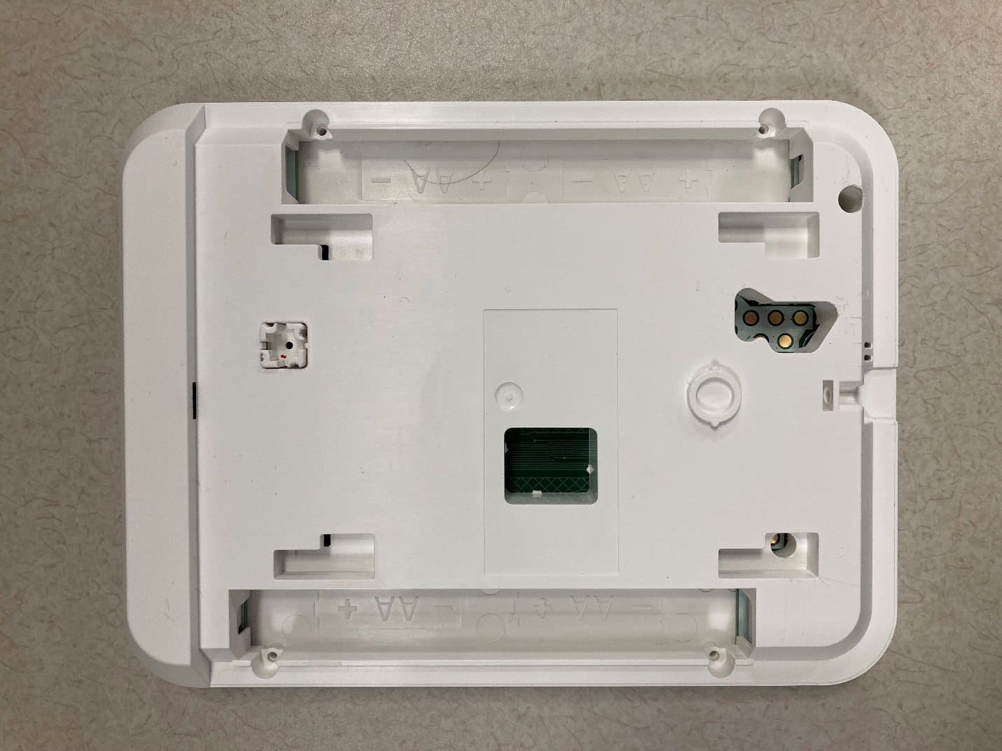
2AAJXQS-IQKP
Aug 19, 2023PowerG Wirefree Keypad with prox
Equipment Class
DSS - Part 15 Spread Spectrum Transmitter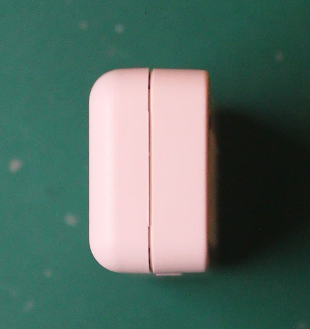
2AAJXQS-IQDWM
Aug 03, 2023Door Sensor Alarm System
Equipment Class
DSC - Part 15 Security/Remote Control Transmitter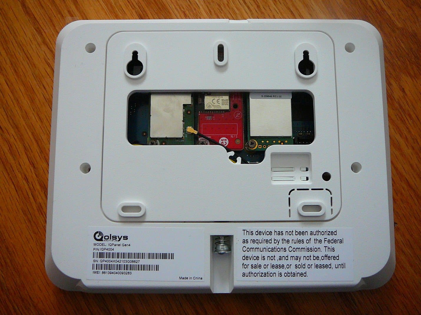
2AAJXQS-IQP4Z
Feb 27, 2023Zwave 800 Radio
Equipment Class
DXX - Part 15 Low Power Communication Device Transmitter
2AAJXQS-IQWIFI6
Aug 25, 2021IQ WiFi 6
Equipment Class
DTS - Digital Transmission System
2AAJXQS-ZWAVEAH
Oct 29, 2020Zwave Module
Equipment Class
DXT - Part 15 Low Power Transceiver, Rx Verified