2AAJXQS2100IQSmartSocket is a Dual Socket that is controlled remotely and measures electricity
Qolsys, Inc.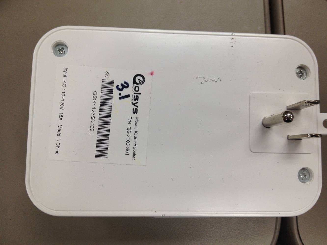
Click to zoom
Application Details
- Equipment Class
- DXT - Part 15 Low Power Transceiver, Rx Verified
- Date of Grant
- Nov 20, 2013
- Application Purpose
- Original Equipment
- Date of Application
- Nov 19, 2013
- Equipment Note
- IQSmartSocket is a Dual Socket that is controlled remotely and measures electricity
- Frequency Range
- 908.40000000 - 908.42000000
- Company
- Qolsys, Inc.
- Country
- United States
Documents & Files
Document Text
Text extracted from the exhibit documents filed with the FCC. Open a document above to read the original.
Users Manual
IQ SMART SOCKET- INSTALLATION MANUAL QOLSYS CONFIDENTIAL AND PROPRIETARY PAGE OF 14 © Last revised 11/4/13 All rights reserved The Qolsys IQ Smart Socket is an intelligent Z-Wave outlet that not only provides the ability to turn devices on or off but measures their current and historical energy output from the built in LCD screen and from the IQ Panel interface. • Provides two individually controlled outlets and green LED lights to indicate each power on. (Max current 15A or 1800W total) • Separately measures energy consumed by two individual attached devices in real-time • Displays individual outlet’s power consumption and constant power rate • Displays real-time power consumption per outlet • Sends current power consumption to IQ Panel via Z-Wave radio • Can be controlled remotely by IQ Panel, to switch each socket on and off or to configure the Smart Socket control parameters. • Sends all configuration status information to the IQ Panel whenever manual button push configuration changes are made on the Smart Socket. • Design includes three buttons, one at bottom of the device and two on the sides of the device • Design includes one Smart Socket Control button on the bottom of the device that shall perform the following functions: • include/pair the smart socket to/from Z-Wave network & IQ Panel • locally reset and un-pair the smart socket to/from IQ Panel • Design includes two side mounted Power Outlet Control buttons, one for each socket. • Each button shall perform the following functions: • turn on/off each outlet • reset the meter data for each outlet • turn on LCD display and LED back light for both outlets • switch from kWh to Watts display units for each outlet • Generate supervisory status signals and transmit to IQ Panel 1 IQ Smart Socket PRODUCT FEATURES PARTS INCLUDED IQ SMART SOCKET IQ SMART SOCKET- INSTALLATION MANUAL QOLSYS CONFIDENTIAL AND PROPRIETARY PAGE OF 24 © Last revised 11/4/13 All rights reserved The front of the Smart Socket has a multi-function LCD display that communicates the power measurements and status information to the user. There are two independent power outlet sockets, one on each side of the IQSmartSocket device. There are two green LED lights on the side of the device so that you may always know if the power is actually on for each of the sockets. The green light will be lit if the power to that socket is on and the light will be off if the power is off. Additionally, there are two Power Outlet Control buttons, one on each side of the IQSmartSocket, that provide control functions for each separate power outlet socket. These two buttons allow the user to manually toggle the power on / off for each separate outlet. The Power Outlet Control buttons also allow the user to change the power measurements and units. ! The IQSmartSocket also has one additional button on the bottom of the device. This Smart Socket Control button allows the user to pair the Smart Socket with the IQ Panel. Additionally, this button allows the user to un-pair the IQSmartSocket from the IQ Panel and clear the device to enable re-pairing. HARDWARE OVERVIEW LCD Display Socket 1 LED light Side 1 control button “Learn” button (hold for 30 sec to reset device) LCD SCREEN Each side of the display shows the cumulative power consumption value (kWh) or power rate value (Watts) of the corresponding outlet. ! I n d i c a t e s the power of smart socket is cut-off for one or more of the following reasons: total current reaches 17A which is 10% o v e r d e s i g n e d m a x i m u m 1 5 Ampere, temperature exceeds 60 o C, and/or voltage exceeds 140V or is less than 95V ! I n d i c a t e s t h a t b o t h o f o u t l e t s a re powered off. ! • Indicates the device is paired with the IQPanel. Z-Wave is a proprietary half-duplex wireless communications protocol designed for home automation. The technology uses a low-power RF radio embedded into home electronics devices and systems, such as lighting, home access control, entertainment systems and household appliances. The Z-Wave wireless protocol is optimized for reliable, low-latency communication of small data packets. Z-WAVE TECHNOLOGY OVERVIEW Operation Frequency908.42(USA) ModulationBFSK/GFSK Bandwidth 9.6 Kbps with a raise to 40Kbps fully interoperable Range Indoor (30m), “open air” condition (100m) Operating Temperature-35C—120C Device Activated Time5ms Total Nodes in one Network232 Securing bracket 1 IQ SMART SOCKET- INSTALLATION MANUAL QOLSYS CONFIDENTIAL AND PROPRIETARY PAGE OF 34 © Last revised 11/4/13 All rights reserved PAIRING THE IQ SMART SOCKET To expedite the pairing process be sure to plug the IQ Smart Socket into an outlet near the IQ Panel. Once pairing is complete the IQ Smart Socket can be moved to any outlet within range. From the home screen of the IQ panel, press the “Settings” icon Enter the installer passcode. Default installer passcode is 1111 12 Select the “Installation” appSelect the “Z-Wave Devices” app 34 Select “Add Device” Press and release the buCon on the boCom of the device 54 A chime will sound Click “Ok” 67 8 Check the auto-populated fields to ensure accuracy. Change the settings as you see fit. 9 Create custom names by selecting “Sensor name” and choosing “Custom description.” A box will appear to the right. Selecting that box will open a keyboard, allowing you to type the name of your choice into the field. 10 Click “Save” to complete the process IQ SMART SOCKET- INSTALLATION MANUAL QOLSYS CONFIDENTIAL AND PROPRIETARY PAGE OF 5 4 © Last revised 11/4/13 All rights reserved UN-PAIRING/RESETTING • Plug in the IQSmartSocket somewhere near the IQ Panel • On the IQ Panel, use the installer passcode to access the Z-Wave installation functions under Settings / Installation / Z-Wave Sensors. • Press the “Clear Device” function on the panel • Next, press the Smart Socket Control button (at the bottom of the IQSmartSocket) - for this function, the user must press the button for at least 50 milliseconds and not hold d…
Text truncated - open the document above for the full version.
Cover Letter(s)
MARK SKEEN VP LIFE SAFETY & COMPLIANCE Attention: mark.sl<[email protected] Application Examiner (408) 8s7-84ls Re: Request for confidentiality Applicant: Qolsys, Inc. FCC ID:2AAJXQS2100 To whom it may concern, P ermsn e n I C o nJi denlia lity Request is hereby submitted by Qolsys, Inc. to withhold permanently from public review certain portions of the application for equipment certification for the referenced FCC identifiers. This request for confidentiality is made pursuant to 47 CFR 0.457(d) and 0.459 of the FCC Rules. In particular, the following sections of the application are to be kept permanently confidential: . Schematics . Detailed Block diagrams . DetailedOperational/FunctionalDescription Qolsys, Inc. has invested considerable time and materials in research and development to produce the referenced product. Disclosure of the permanently confidential portions of this application to competitors would not only give them significant competitive advantages in developing similar products, but would also disclose successful implementation of unpublished, leading edge technology developed by us. If you have questions or need further information, please contact the undersigned. Sincerely, /a^n n /-) /rl/ Lrt r,(/(_- \-.2 Mark Skeen VP Life, Safety and Compliance Qolsys, Inc. l(1) i
External Photos
External Photographs FCC ID: 2AAJXQS2100 IC: 11205A-QS2100
ID Label/Location Info
QSGXYYWW00001 Input : AC 110~120V, 15A Dev ID: XXXXXXXX Made in China P/N: QS-2100-P01 Model: IQSmartSocket SN: This device complies with FCC Part 15 and Industry Canada Rules and Regulations. Operation is subject to the following conditions: (1) This device may not cause harmful interference and (2) this device must accept any interference received, including interference that may cause undesired operation. See User’s Manual for safety instructions 09/2013 FCC ID: 2AAJXQS2100 IC: 11205A-QS2100 Conforms to ANSI/UL Std 498A Certified to CSA Std C22.2 # 42 45 51 Smart Socket Label scale:1:1, unit:mm Location Note: 1. Font size: 1.5mm 4008507 QSGXYYWW00001 Input : AC 110~120V, 15A Dev ID: XXXXXXXX Made in China P/N: QS-2100-P01 Model: IQSmartSocket SN: This device complies with FCC Part 15 and Industry Canada Rules and Regulations. Operation is subject to the following conditions: (1) This device may not cause harmful interference and (2) this device must accept any interference received, including interference that may cause undesired operation. See User’s Manual for safety instructions 09/2013 FCC ID: 2AAJXQS2100 IC: 11205A-QS2100 Conforms to ANSI/UL Std 498A Certified to CSA Std C22.2 # 42 4008507 See User’s Manual for safety instructions
Internal Photos
Internal Photographs FCC ID: 2AAJXQS2100 IC: 11205A-QS2100
Test Setup Photos
Setup Photographs FCC ID: 2AAJXQS2100 IC: 11205A-QS2100 Radiated Emissions Radiated Emissions AC Line Conducted Emission
Contact Information
Applicant
Mark Skeen(VP Business Development, Global Products)
Technical Contact
Intertek Testing Services NA, Inc.Krishna Vemuri
[email protected]650-463-2900
1365 Adams Court · Menlo Park, California · United States
Non-Technical Contact
Intertek Testing Services NA, Inc.Krishna Vemuri
[email protected]650-4632900
Test Firm
Intertek Testing Services NA Inc.John Quigley
Technical Specifications
| # | Rule Parts | Frequency Range | Power Output |
|---|---|---|---|
| 1 | 15C | 908.4 MHz - 908.42 MHz | - |
Other Applications from Qolsys, Inc.
2AAJXQS-IQKP
Aug 19, 2023PowerG Wirefree Keypad with prox
Equipment Class
DSS - Part 15 Spread Spectrum Transmitter
2AAJXQS-IQDWM
Aug 03, 2023Door Sensor Alarm System
Equipment Class
DSC - Part 15 Security/Remote Control Transmitter
2AAJXQS-IQP4Z
Feb 27, 2023Zwave 800 Radio
Equipment Class
DXX - Part 15 Low Power Communication Device Transmitter
2AAJXQS-IQWIFI6
Aug 25, 2021IQ WiFi 6
Equipment Class
DTS - Digital Transmission System
2AAJXQS-ZWAVEAH
Oct 29, 2020Zwave Module
Equipment Class
DXT - Part 15 Low Power Transceiver, Rx Verified