2AASJSMD-1770BMobile Phone
Daewoo International Corp.
Click to zoom
Application Details
- Equipment Class
- PCE - PCS Licensed Transmitter held to ear
- Date of Grant
- Aug 18, 2013
- Application Purpose
- Original Equipment
- Date of Application
- Aug 18, 2013
- Equipment Note
- Mobile Phone
- Frequency Range
- 1850.20000000 - 1909.80000000
- Company
- Daewoo International Corp.
- Country
- South Korea
Documents & Files
Document Text
Text extracted from the exhibit documents filed with the FCC. Open a document above to read the original.
Users Manual
1 GSM Mobile Phone User Manual Trade name:DAEWOO Model name:SMD-1770B FCC ID:2AASJSMD-1770B 2 SMD-1770B SUPER USER MANUAL 1. Overview Thank you for purchasing a SMD-1770B mobile phone. 2. Warnings Not following these simple guidelines may be dangerous or illegal. Read the complete user guide for further information. TURN ON SAFELY Do not turn on the phone when wireless phones are prohibited or when it may cause interference or danger. ROAD SAFETY Obey all road safety laws. Always use both of your hands to operate the vehicle while driving. INTERFERENCE All wireless phones may be sensitive to interference, which may affect performance. TURN OFF IN HOSPITALS Follow all restrictions. Turn off the phone near medical equipment. TURN OFF ON AIRCRAFTS Follow all restrictions. Wireless devices can cause interference on aircrafts. TURN OFF WHEN REFUELING Do not use the phone at/near refueling stations. Do not use near fuel or chemicals. USE SENSIBLY Only qualified personnel may install or repair this product. ENHANCEMENTS AND BATTERIES Use only appropriate enhancements and batteries. Do not connect incompatible products. WATER-RESISTANCE Your phone is not water-resistant. Keep it dry. BACKUP COPIES Remember to make back-up copies or keep a written record of all important information stored in your phone. CONNECTING TO OTHER DEVICES When connecting to any external device, read its user guide for detailed safety instructions. Do not connect with incompatible products. 3 3. Getting Started 3.1 SIM Card Installation When you subscribe to a cellular network, you will receive a plug-in SIM card complete with your subscription details, such as your PIN, and available optional services. Caution: Do not bend or scratch your SIM card. Avoid exposing your SIM card to static electricity, water, or dirt. Tips:Face the gold color contact point of SIM card towards the cell phone and push the SIM card into the slot. 3.2 Battery Installation 4 Caution: Install according to the illustration above to avoid breaking the battery connectors. 3.3 Charging the Battery Insert the charger; the flash symbol on the charger plug must face upwards. Connect the charger to a standard wall outlet and the battery power icon in the upper - right corner of the screen will start scrolling. When the battery bar stops scrolling, the battery charge is complete. Press the two sides of the charger plug and disconnect the charger from the phone. ·When the battery is low, a "low battery" message will display across the screen and the battery icon will seem empty. If the battery level is insufficient, the phone will turn off automatically. Do not use your phone in a low battery state for an extended period of time or it may cause battery damage. 3.4 Security Settings —PIN code PIN code (Personal Identity Number) prevents unauthorized use of your phone. The PIN code is provided by your network operator with the SIM card. 5 If you enter the wrong code three times in a row, the PIN code will be blocked. To unblock the PIN code, you need to enter your PUK. Your PUK is provided by your network operator. -Power on Pwd Activate/Modify/Deactivate power on password (the length of the password is 4-8 digital numbers). If you activate the "Power on Pwd", you need to enter the password each time you turn on the phone. If you want to modify or deactivate power on password, enter Modify/ Deactivate option to set. 4. Your Phone 4.1 Power On ·Press and hold power key to turn on your phone, light the backlight, and display power on animation. ·If you do not insert a SIM card, or the SIM card has incomplete connection, your phone will show “Insert SIM”. In this condition, you can only access part of the menu and only permission using some urgent calling. ·If the PIN code is blocked, the alert message for inputting PUK code will display on the screen before power on. ·The phone will search the network automatically after power on. If your phone registers to network correctly, the name of the network and signal strength will display; if your phone can’t register or can’t register correctly, you can only access emergency calls and other functions that do not rely on the network. 4.2 Making a Call In standby mode, press numerical keys to input phone number to dial phone number. When you finish inputting phone number, press the dial key or left soft key to make a call. If you're making a long distance call, add the area code preceding the telephone number. Press OK key to access Option. -Add to phone book: Add a phone number to telephone directory -Add to existing contact: Add the phone number existing contact -Send SMS: Send message to a certain number -Insert wpn: Pause P/Wait W -SIM 1 call: Dial the number of SIM card 1 -SIM 2 call: Dial the number of SIM card 2 4.3 Rejecting a Call Press end key to reject an incoming call. 4.4 Answering a Call When you receive a call, the phone will ring or vibrate and will display an incoming call indicator. Press the dial key, OK key, or left soft key to answer. Press left soft key to access menu: 6 ·Turn on handsfree option ·Shuttle ·Names ·Messages ·Call history ·Start recording ·Mute ·DTMF on/off 4.5 Volume Settings During a call, press navigation keys to adjust the volume. 4.6 Ending Calls Press the end key to end or cancel a call. 4.7 Emergency Service You can dial an emergency number without the SIM card. Contact your service provider to get the emergency call number. 4.8 Extension Call/Quick Dial After inputting phone number, quickly press key (*) thrice until the symbol “P” appears, then input the extra number. 4.9 Missed/ Dialed Call Enter main menu->Call History -> check Missed/Dialed calls. In standby mode, press dial key to check Dialed calls. 4.10 Call Divert When the call divert is activated, incoming calls will be diverted to voice mail or other phone numbers according to the call divert settings. 4.11 Call Barring When the call barring activated, some of the calls will be barred according to the call barring…
Text truncated - open the document above for the full version.
Cover Letter(s)
Daewoo International Corp. 84-11, Namdaemunno 5-ga, Jung-gu, Seoul 100-753 Korea Date: Aug. 12, 2013 Statement We, Daewoo International Corp. states that our device, FCC ID: 2AASJSMD‐1770B, has no space to put the label except the battery compartment of this device. It is visible to the users as they purchase the products and install the battery. Regards Company: Daewoo International Corp. Contact Person: Young Kyoo Yoo Title: Manager
External Photos
SMD‐1770B External Photos TOTAL VIEW OF EUT TOP VIEW OF EUT BOTTOM VIEW OF EUT FRONT VIEW OF EUT BACK VIEW OF EUT LEFT VIEW OF EUT RIGHT VIEW OF EUT
ID Label/Location Info
FCC ID Label Location GSM Mobile Phone Model: SMD-1770B Trade Name: DAEWOO FCC ID: 2AASJSMD-1770B
Internal Photos
SMD‐1770B Internal Photos OPEN VIEW OF EUT‐1 OPEN VIEW OF EUT‐2 OPEN VIEW OF EUT‐3 INTERNAL VIEW OF EUT‐1 GSM Antenna INTERNAL VIEW OF EUT‐2 INTERNAL VIEW OF EUT‐3
RF Exposure Info
FCC ID PRODU APPLIC BRAND MODEL CLIENT DATE O STAND REPOR A CAUTIO This rep laborato UCT DESIGN CATION PUR D NAME L NAME T OF ISSUE DARD(S) RT VERSION Attestat ON: port shall n ory and sha SA Rep : NATION : RPOSE : : : : : : : tion of G not be repro all not be q R Te port No.: A 2AASJSM D GSM Mob Original E DAEWOO SMD‐177 Daewoo I Aug.07, 2 FCC Oet65 IEEE Std. 47CFR § 2 V1.0 Global C oduced exc uoted out o est AGC0020 D‐1770B ile Phone Equipment 0B nternational 013 5 Supplemen 1528‐2003 2.1093 Complia cept in full w of context. Rep 00130801 l Corp. nt C June 200 ance(Sh without the Report port 1FH01 01 henzhen e written p t No.:AGC00 t n) Co., L ermission 0200130801 Page 1 Ltd. of the test FH01 of 98 Report No.:AGC00200130801FH01 Page 2 of 98 Report Revise Record Report Version Revise Time Issued Date Valid Version Notes V1.0 / Aug.07, 2013 Valid Original Report Applica Applica Manufa Manufa Product Brand N Model N Differen EUT Vo Applica Te s t Da Te s t Re Perform Report T nt Name nt Address cturer Name cturer Addre t Designatio Name Name nt Descriptio oltage ble Standard ate esults med Location Template Tes D 84 e U ess R R n G DA S on N/ D d FC IE 47 A M H ( M n At 2 G A Docume Check e Authoriz st Rep aewoo Inter 4-11, Namda nited Creati oom 201, B oad 1057, S SM Mobile AEWOO MD-1770B /A C3.7V by ba CC Oet65 S EEE Std. 152 7CFR § 2. ug.07, 2013 MAX SAR ME ead: 0.518 W Maximum Sc ttestation of F, Building ushu, Xixian GCRT-US-2 nted By ed By zed By port C rnational Co aemunno 5- on Technolo Block A, Scie Shekou, Nan Phone attery Supplement 28-2003 .1093 3 EASUREME W/Kg Bod caling SAR = fGlobal Com g 2, No.1-N ng Street, B 2.5G2/SAR ( Vivi Ze Angel a Solger Z Certific orp. -ga, Jung-gu ogy Co., Ltd ence and tec nshan distric C June 200 ENT(1g) y: 0.726 W /K =0.837 W/K mpliance(Sh No.4, Chaxi ao'an Distri c (2013-03-01 eng A a Li A hang A Report cation u, Seoul 100 . chnology bu ct, Shenzhen 1 Kg g) enzhen) Co Sanwei Tec ct, Shenzhe ) Aug.07, 201 Aug.07, 201 Aug.07, 201 t No.:AGC00 n 0-753 Korea uilding phase n, CN. o., Ltd. chnical Indu n, China 13 13 13 0200130801 Page 3 e-II, Nanhai ustrial Park, FH01 of 98 Report No.:AGC00200130801FH01 Page 4 of 98 TABLE OF CONTENTS 1. GENERAL INFORMATION ............................................................................................................................ 5 1.1. EUT DESCRIPTION ...................................................................................................................................... 5 1.2. TEST PROCEDURE ...................................................................................................................................... 7 1.3. TEST ENVIRONMENT .................................................................................................................................... 7 2. SAR MEASUREMENT SYSTEM ..................................................................................................................... 8 2.1. COMOSAR SYSTEM DESCRIPTION .............................................................................................................. 8 2.2. COMOSAR E-FIELD PROBE ..................................................................................................................... 10 2.3. ROBOT ..................................................................................................................................................... 10 2.4. VIDEO POSITIONING SYSTEM ...................................................................................................................... 11 2.5. DEVICE HOLDER ........................................................................................................................................ 11 2.6. SAM TWIN PHANTOM ................................................................................................................................ 12 3. TISSUE SIMULATING LIQUID ..................................................................................................................... 13 3.1. THE COMPOSITION OF THE TISSUE SIMULATING LIQUID ................................................................................... 13 3.2. TISSUE CALIBRATION RESULT ..................................................................................................................... 14 3.3. TISSUE DIELECTRIC PARAMETERS FOR HEAD AND BODY PHANTOMS .............................................................. 15 4. SAR MEASUREMENT PROCEDURE ......................................................................................................... 16 4.1. SAR SYSTEM VALIDATION .......................................................................................................................... 16 4.2. SAR MEASUREMENT PROCEDURE ............................................................................................................. 18 5. SAR EXPOSURE LIMITS ............................................................................................................................ 19 6. TEST EQUIPMENT LIST ............................................................................................................................. 20 7. MEASUREMENT UNCERTAINTY ................................................................................................................ 21 8. CONDUCTED POWER MEASUREMENT .................................................................................................... 22 9. TEST RESULTS .......................................................................................................................................... 23 9.1. SAR TEST RESULTS SUMMARY .................................................................................................................. 23 APPENDIX A. SAR SYSTEM VALIDATION DATA .......................................................................................... 28 APPENDIX B. SAR MEASUREMENT DATA.............................................…
Text truncated - open the document above for the full version.
RF Exposure Info
Report No.:AGC00200130801FH01 Page 60 of 98 Appendix C. TEST SETUP PHOTOGRAPHS &EUT PHOTOGRAPHS Test Setup Photographs LEFT-CHECK TOUCH LEFT-TILT 15 0 Report No.:AGC00200130801FH01 Page 61 of 98 RIGHT-CHECK TOUCH RIGHT-TILT 15 0 Report No.:AGC00200130801FH01 Page 62 of 98 Body Back 5mm Body Front 5mm 5mm Report No.:AGC00200130801FH01 Page 63 of 98 DEPTH OF THE LIQUID IN THE PHANTOM—ZOOM IN Note:The position used in the measurement were according to IEEE 1528-2003 Report No.:AGC00200130801FH01 Page 64 of 98 EUT PHOTOGRAPHS ALL VIEW OF EUT-1 ALL VIEW OF EUT-2 Report No.:AGC00200130801FH01 Page 65 of 98 TOP VIEW OF EUT BOTTOM VIEW OF EUT Report No.:AGC00200130801FH01 Page 66 of 98 FRONT VIEW OF EUT BACK VIEW OF EUT Report No.:AGC00200130801FH01 Page 67 of 98 LEFT VIEW OF EUT RIGHT VIEW OF EUT Report No.:AGC00200130801FH01 Page 68 of 98 OPEN VIEW OF EUT-1 OPEN VIEW OF EUT-2 Report No.:AGC00200130801FH01 Page 69 of 98 OPEN VIEW OF EUT-3 INTERNAL VIEW OF EUT-1 GSM Antenna Report No.:AGC00200130801FH01 Page 70 of 98 INTERNAL VIEW OF EUT-2 INTERNAL VIEW OF EUT-3
RF Exposure Info
Report No.:AGC00200130801FH01 Page 71 of 98 Appendix D. Probe Calibration Data Report No.:AGC00200130801FH01 Page 72 of 98 Report No.:AGC00200130801FH01 Page 73 of 98 Report No.:AGC00200130801FH01 Page 74 of 98 Report No.:AGC00200130801FH01 Page 75 of 98 Report No.:AGC00200130801FH01 Page 76 of 98 Report No.:AGC00200130801FH01 Page 77 of 98 Report No.:AGC00200130801FH01 Page 78 of 98 Report No.:AGC00200130801FH01 Page 79 of 98 Report No.:AGC00200130801FH01 Page 80 of 98 Report No.:AGC00200130801FH01 Page 81 of 98 Appendix E. Dipole Calibration Data Report No.:AGC00200130801FH01 Page 82 of 98 Report No.:AGC00200130801FH01 Page 83 of 98 Report No.:AGC00200130801FH01 Page 84 of 98 Report No.:AGC00200130801FH01 Page 85 of 98 Report No.:AGC00200130801FH01 Page 86 of 98 Report No.:AGC00200130801FH01 Page 87 of 98 Report No.:AGC00200130801FH01 Page 88 of 98 Report No.:AGC00200130801FH01 Page 89 of 98 Report No.:AGC00200130801FH01 Page 90 of 98 Report No.:AGC00200130801FH01 Page 91 of 98 Report No.:AGC00200130801FH01 Page 92 of 98 Report No.:AGC00200130801FH01 Page 93 of 98 Report No.:AGC00200130801FH01 Page 94 of 98 Report No.:AGC00200130801FH01 Page 95 of 98 Report No.:AGC00200130801FH01 Page 96 of 98 Report No.:AGC00200130801FH01 Page 97 of 98 Report No.:AGC00200130801FH01 Page 98 of 98
Test Report
Report No.: AGC00200130801FE02 Page 1 of 61 FCC Test Report Report No.: AGC00200130801FE02 FCC ID : 2AASJSMD‐1770B APPLICATION PURPOSE : Original Equipment PRODUCT DESIGNATION : GSM Mobile Phone BRAND NAME : DAEWOO MODEL NAME : SMD‐1770B CLIENT : Daewoo International Corp. DATE OF ISSUE : Aug.12,2013 STANDARD(S) : FCC Part 22H & 24E Rules REPORT VERSION : V1.0 Attestation of Global Compliance (Shenzhen) Co., Ltd. CAUTION: This report shall not be reproduced except in full without the written permission of the test laboratory and shall not be quoted out of context. Report No.: AGC00200130801FE02 Page 2 of 61 REPORT REVISE RECORD Report Version Revise Time Issued Date Valid VersionNotes V1.0 / Aug.12,2013Valid Original Report Report No.: AGC00200130801FE02 Page 3 of 61 TABLE OF CONTENTS 1. GENERAL INFORMATION ..................................................................................................................... 7 1.1 PRODUCT DESCRIPTION ................................................................................................................................ 7 1.2 RELATED SUBMITTAL(S) / GRANT (S) ............................................................................................................ 8 1.3 TEST METHODOLOGY ..................................................................................................................................... 9 1.4 TEST FACILITY .................................................................................................................................................. 9 1.5 MEASUREMENT INSTRUMENTS .................................................................................................................... 9 1.6 SPECIAL ACCESSORIES ................................................................................................................................. 9 1.7 EQUIPMENT MODIFICATIONS ......................................................................................................................... 9 2. SYSTEM TEST CONFIGURATION ....................................................................................................... 10 2.1 EUT CONFIGURATION ................................................................................................................................... 10 2.2 EUT EXERCISE ............................................................................................................................................... 10 2.3 GENERAL TECHNICAL REQUIREMENTS .................................................................................................... 10 2.4 CONFIGURATION OF EUT SYSTEM ............................................................................................................. 11 3. SUMMARY OF TEST RESULTS ........................................................................................................... 12 4. DESCRIPTION OF TEST MODES ........................................................................................................ 12 5. OUTPUT POWER ................................................................................................................................. 13 5.1 CONDUCTED OUTPUT POWER .................................................................................................................... 13 5.2 RADIATED OUTPUT POWER ......................................................................................................................... 16 6. PEAK-TO-AVERAGE RATIO ................................................................................................................ 20 6.1 MEASUREMENT METHOD ............................................................................................................................. 20 6.2 PROVISIONS APPLICABLE ............................................................................................................................ 20 6.3 MEASUREMENT RESULT .............................................................................................................................. 21 7. SPURIOUS EMISSION ......................................................................................................................... 22 7.1 CONDUCTED SPURIOUS EMISSION ............................................................................................................ 22 7.2 RADIATED SPURIOUS EMISSION ................................................................................................................. 24 8. MAINS CONDUCTED EMISSION ......................................................................................................... 28 Report No.: AGC00200130801FE02 Page 4 of 61 8.1 MEASUREMENT METHOD ............................................................................................................................. 28 8.2 PROVISIONS APPLICABLE ............................................................................................................................ 28 8.3 MEASUREMENT RESULT .............................................................................................................................. 29 9. FREQUENCY STABILITY ..................................................................................................................... 31 9.1 MEASUREMENT METHOD ............................................................................................................................. 31 9.2 PROVISIONS APPLICABLE ............................................................................................................................ 31 9.3 MEASUREMENT RESULT (WORST TEST) ................................................................................................... 32 10. OCCUPIED BANDWIDTH ................................................................................................................... 34 10.1 MEASUREMENT METHOD ...................................................................................…
Text truncated - open the document above for the full version.
Test Setup Photos
APPENDIX IV PHOTOGRAPHS OF TEST SETUP CONDUCTED EMISSION RADIATED SPURIOUS EMISSION
Contact Information
Applicant
D.S.Yoo Yoo
Test Firm
Attestation of Global Compliance Shenzhen Co. Ltd.Forrest Lei
Technical Specifications
| # | Rule Parts | Frequency Range | Power Output | Emission | Tolerance |
|---|---|---|---|---|---|
| 2 | 24E | 1.85 GHz - 1.91 GHz | 687.00 mW | 245KGXW | 0.023 ppm |
Other Applications from Daewoo International Corp.

2AASJSMD-5018A
Aug 24, 2014Mobile Phone
Equipment Class
PCE - PCS Licensed Transmitter held to ear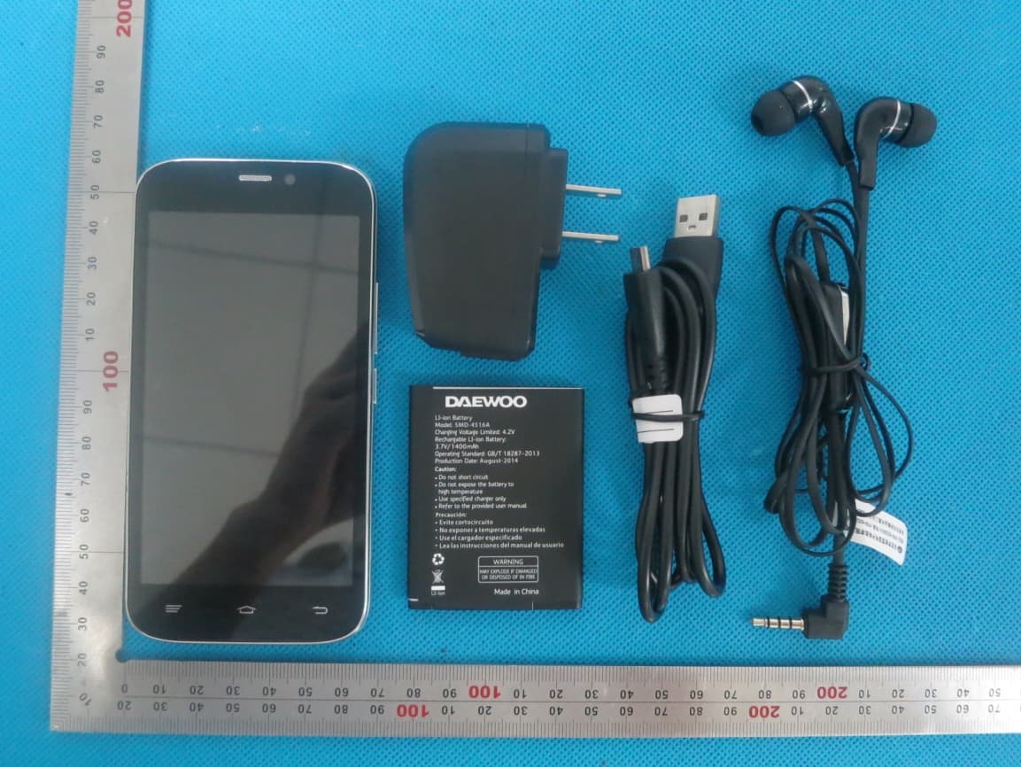
2AASJSMD-4516A
Aug 17, 2014Mobile Phone
Equipment Class
DTS - Digital Transmission System
2AASJSMD-4016A
Aug 16, 2014Mobile Phone
Equipment Class
DSS - Part 15 Spread Spectrum Transmitter
2AASJSTP-103
Jun 11, 2014Tablet
Equipment Class
DTS - Digital Transmission System