2AASJSMD-4516AMobile Phone
Daewoo International Corp.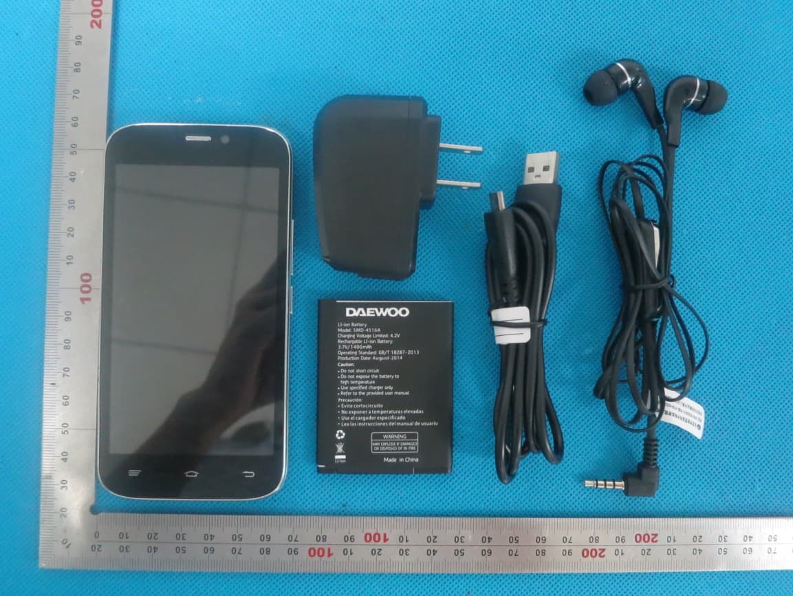
Click to zoom
Application Details
- Equipment Class
- DTS - Digital Transmission System
- Date of Grant
- Aug 17, 2014
- Application Purpose
- Original Equipment
- Date of Application
- Aug 17, 2014
- Equipment Note
- Mobile Phone
- Frequency Range
- 2402.00000000 - 2480.00000000
- Company
- Daewoo International Corp.
- Country
- South Korea
Documents & Files
Document Text
Text extracted from the exhibit documents filed with the FCC. Open a document above to read the original.
Users Manual
1 SMD-4516A User Manual Brand Name: DAEWOO Model Name: SMD-4516A FCC ID: 2AASJSMD-4516A 2 Warnings Not following these simple guidelines may be dangerous or illegal. Read the complete user guide for further information. TURN ON SAFELY Do not turn on the phone when wireless phone is prohibited or when it may cause interference or danger. ROAD SAFETY Obey all road safety laws. Always use both of your hands to operate the vehicle while driving. INTERFERENCE All wireless phones may be sensitive to interference, which may affect performance. TURN OFF IN HOSPITALS Follow all restrictions. Turn off the phone near medical equipment. TURN OFF ON AIRCRAFTS Follow all restrictions. Wireless devices can cause interference on aircrafts. 3 TURN OFF WHEN REFUELING Do not use the phone at/near refueling stations. Do not use near fuel or chemicals. USE SENSIBLY Only qualified personnel may install or repair this product. ENHANCEMENTS AND BATTERIES Use only appropriate enhancements and batteries. Do not connect incompatible products. WATER-RESISTANCE Your phone is not water-resistant. Keep it dry. BACKUP COPIES Remember to make back-up copies or keep a written record of all important information stored in your phone. CONNECTING TO OTHER DEVICES When connecting to any external device, read its user guide for detailed safety instructions. Do not connect with incompatible products. 4 Content Your Phone .................................................................................................................... ................5 Keypad Descriptions ........................................................................................................... ..........6 Input Method .................................................................................................................. ...............6 Start to Use .................................................................................................................. ..................7 Charge the Battery ............................................................................................................ ............8 Use Touch Screen .............................................................................................................. ............8 Make a Call ................................................................................................................... ................9 Answer a Call ................................................................................................................. ...............9 Emergency Service ............................................................................................................. ........10 Base Function ................................................................................................................. .............10 Widgets ....................................................................................................................... ................17 Accessories.................................................................................................................... ..............18 Care and Maintenance .......................................................................................................... .......18 Technical Information ......................................................................................................... ........21 5 Your Phone 6 Keypad Descriptions Key Description Power Key (Right side) Long press the key to turn on the phone. In the power on status, press the key to lock keypad and screen; long press the key to show phone options. Back Key In the menu mode, press the key to go back to upper menu. Home Key Press the key to return to standby mode. Long press the key to show recent list. Option Key Press the key to enter option menu. Vo l u m e K e y s(Right side) To adjust incoming call ringtone volume. During a call, playing music, video, or listening to radio, press the keys to adjust volume. Input Method Your phone has the built-in input method. In edit mode, long press “ , ... ” to show Input options and set input languages and Android keyboard settings. Input English 7 Press the on-screen keypad to enter corresponding letters. Input Number Press “ ?123 ”, you can input numbers directly by press the number icons. Long press the letter icons with number, or after long press, slide finger to the numbers to input. Input Symbol Press “ ?123 ” to enter symbol list. Press the desired symbol to input. Long press “ . ... ” or “ :-) ... ” to show symbol list, slide finger to the desired symbol to input. Start to Use Install Memory Card, SIM Card and Battery When you apply for a network, you will get a plug-in SIM card. SIM (Subscriber Identity Module) card that contains phone number, service projects and can be used to store phone numbers and personal information. Attention: Do not bend or scratch SIM card, do not let it contact with static electricity, dust or water. Keep all SIM cards where children cannot reach or touch. Note: Keep the SIM card chip contacts face downward. Make the SIM card fits card slot. Remove Memory Card, SIM Card and Battery 8 Note: If the phone is turned on, long press power key about 3 seconds until it tips phone options and select Power off and then press OK to turn off the phone. Then, remove the battery, SIM card and memory card. Do not plug or remove memories card in boot state; otherwise it will cause damage to the file system. Charge the Battery 1. Before charging, check the battery slot to ensure the battery has been installed correctly. 2. Plug one end of the charger into phone. 3. Connect another end of the charger to the socket. 4. Start charging. It can be charged whether power on or power off. ▪ In power on state, when the battery icon on screen start rolling means it is been charged. When the icon is full and stop rolling means charge is completed. ▪ In power off state, the battery icon on screen start rolling means it is been cha…
Text truncated - open the document above for the full version.
Cover Letter(s)
Aug. 14, 2014 Federal Communication Commission Authorization and Evaluation Division FCC ID: 2AASJSMD-4516A Re: Confidentiality Request Pursuant to Sections 0.457 and 0.459 of the Commission’s Rules, the applicant hereby requests confidential treatment of information applied this application as outlined below: 1: Block Diagram 2: Circuit Diagram 3: Operational Description 4: Parts List 5: Turn Up Procedure The above materials contain trade secrets and proprietary information not customarily released to the public. The public disclosure of these matters might be harmful to the applicant and provide unjustified benefits to its competitors. The Applicant understands that pursuant to Rules 0.457, disclosure of this Application and all accompanying documentation will not be made before the date of the Grant for this application. Sincerely, Company: Daewoo International Corp. Contact Person: Young Kyoo Yoo Title: Manager
Cover Letter(s)
Ersteller: D. Brandhorst Revision: 00 Erstelldatum: 13.06.2014 Datum: 00.00.00 Seite 1 von 1 Daewoo International Corp. 84-11, Namdaemunno 5-ga, Jung-gu, Seoul 100-753 Korea Date: Aug. 14, 2014 Subject: Declaration Operating Channel Limitation FCC ID: 2AASJSMD-4516A To Whom it may concern, This device is acting either as slave/client device under the control of a master, or as a master device in Ad Hoc Mode and/or Hot Spot Mode. The operating channels in 802.11 b/g/n mode for the device marketed to the US/Canada are firmware limited to channel 1 ~ 11 (2412 ~ 2462 MHz). The end-user has no possibility to select any other operating channels. Please contact the one signed below or the authorized agent for this filing. Thank you. Regards, Daewoo International Corp. Contact person: Young Kyoo Yoo Title: Manager
Cover Letter(s)
Daewoo International Corp. 84-11, Namdaemunno 5-ga, Jung-gu, Seoul 100-753 Korea Date: Aug. 14, 2014 Statement We, Daewoo International Corp. states that our device, FCC ID: 2AASJSMD-4516A, has no space to put the label except the battery compartment of this device. It is visible to the users as they purchase the products and install the battery. Regards Company: Daewoo International Corp. Contact person: Young Kyoo Yoo Title: Manager
External Photos
External Photos TOTAL VIEW OF EUT TOP VIEW OF EUT BOTTOM VIEW OF EUT FRONT VIEW OF EUT BACK VIEW OF EUT LEFT VIEW OF EUT RIGHT VIEW OF EUT
ID Label/Location Info
FCC ID Mode Trade FCC Label Lo el: SMD-4516A e Name: DAEW ID: 2AASJSM ocation A WOO MD-4516A
Internal Photos
Internal Photos OPEN VIEW OF EUT-1 OPEN VIEW OF EUT-2 GSM & WCDMA Antenna WIFI&BT Antenna GPS Antenna OPEN VIEW OF EUT-3 INTERNAL VIEW OF EUT-1 INTERNAL VIEW OF EUT-2
RF Exposure Info
Report No.:AGC00200140802FH01 Page 1 of 189 SAR Test Report Report No.: AGC00200140802FH01 FCC ID : 2AASJSMD-4516A APPLICATION PURPOSE : Original Equipment PRODUCT DESIGNATION : Mobile Phone BRAND NAME : DAEWOO MODEL NAME : SMD-4516A CLIENT : Daewoo International Corp DATE OF ISSUE : Aug. 12,2014 STANDARD(S) : IEEE Std. 1528:2003 47CFR § 2.1093 IEEE/ANSI C95.1 REPORT VERSION : V1.0 Attestation of Global Compliance(Shenzhen) Co., Ltd. CAUTION: This report shall not be reproduced except in full without the written permission of the test laboratory and shall not be quoted out of context. Report No.:AGC00200140802FH01 Page 2 of 189 Report Revise Record Report Version Revise Time Issued Date Valid Version Notes V1.0 / Aug. 12,2014 Valid Original Report The test plans were performed in accordance with IEEE Std. 1528:2003; 47CFR § 2.1093; IEEE/ANSI C95.1 and the following specific FCC Test Procedures: ·KDB 447498 D01 General RF Exposure Guidance v05r02 ·KDB 648474 D04 SAR Handsets Multi Xmiter and Ant v01 ·KDB 865664 D01 SAR measurement 100 MHz to 6 GHz v01r03 ·KDB 941225 D01 SAR test for 3G devices v02 ·KDB 941225 D02 Guidance for 3GPP R6 and R7 HSPA v02r02 ·KDB 941225 D03 SAR Test Reduction GSM GPRS EDGE v01 ·KDB 941225 D06 Hot Spot SAR v01 ·KDB 248227 D01 SAR meas for 802 11 a b g v01r02 Report No.:AGC00200140802FH01 Page 3 of 189 Test Report Certification Applicant Name Daewoo International Corp Applicant Address 84-11, Namdaemunno 5-ga, Jung-gu, Seoul 100-753 Korea Manufacturer Name SGMC Co., Ltd. Manufacturer Address 5F Media Tower, 108-9 Sungsan 1-dong, Mapo-gu, Seoul 121-844 Korea Product Designation Mobile Phone Brand Name DAEWOO Model Name SMD-4516A Different Description N/A EUT Voltage DC3.7V by battery Applicable Standard IEEE Std. 1528:2003 47CFR § 2.1093 IEEE/ANSI C95.1 Test Date Aug. 12,2014 Performed Location Attestation of Global Compliance(Shenzhen) Co., Ltd. 2 F, Building 2, No.1-No.4, Chaxi Sanwei Technical Industrial Park, Gushu, Xixiang Street, Bao'an District, Shenzhen, China Report Template AGCRT-US-3G3/SAR (2014-04-01) Tested By Eric Zhou Aug. 12,2014 Checked By Angela Li Aug. 12,2014 Authorized By Solger Zhang Aug. 12,2014 Report No.:AGC00200140802FH01 Page 4 of 189 TABLE OF CONTENTS 1. SUMMARY OF MAXIMUM SAR VALUE ....................................................................................................... 5 2. GENERAL INFORMATION ............................................................................................................................ 6 2.1. EUT DESCRIPTION ...................................................................................................................................... 6 2.2. TEST PROCEDURE ...................................................................................................................................... 8 2.3. TEST ENVIRONMENT .................................................................................................................................... 8 2.4. TEST CONFIGURATION AND SETTING ............................................................................................................. 9 3. SAR MEASUREMENT SYSTEM ................................................................................................................... 10 3.1. SPECIFIC ABSORPTION RATE (SAR) ........................................................................................................... 10 3.2. SAR MEASUREMENT PROCEDURE .............................................................................................................. 11 3.3. COMOSAR SYSTEM DESCRIPTION ............................................................................................................ 12 3.4. COMOSAR E-FIELD PROBE ..................................................................................................................... 14 3.5. ISOTROPIC E-FIELD PROBE SPECIFICATION ................................................................................................. 14 3.6. ROBOT ..................................................................................................................................................... 14 3.7. VIDEO POSITIONING SYSTEM ..................................................................................................................... 15 3.8. DEVICE HOLDER ....................................................................................................................................... 15 3.9. SAM TWIN PHANTOM ................................................................................................................................ 16 4. TISSUE SIMULATING LIQUID ...................................................................................................................... 17 4.1. THE COMPOSITION OF THE TISSUE SIMULATING LIQUID ................................................................................... 17 4.2. TISSUE CALIBRATION RESULT ..................................................................................................................... 18 4.3. TISSUE DIELECTRIC PARAMETERS FOR HEAD AND BODY PHANTOMS .............................................................. 19 5. SAR MEASUREMENT PROCEDURE ......................................................................................................... 20 5.1. SAR SYSTEM VALIDATION PROCEDURES .................................................................................................... 20 5.2. SAR SYSTEM VALIDATION .......................................................................................................................... 21 6. EUT TEST POSITION ................................................................................................................................... 23 6.1. DEFINE TWO IMAGINARY LINES ON THE HANDSET ......................................................................................... 23 6.2. CHEEK POSITION ................................…
Text truncated - open the document above for the full version.
Test Report
Report No.: AGC00200140802FE04 Page 1 of 68 Report No.: AGC00200140802FE04 FCC ID : 2AASJSMD-4516A APPLICATION PURPOSE : Original Equipment PRODUCT DESIGNATION : Mobile Phone BRAND NAME : DAEWOO MODEL NAME : SMD-4516A CLIENT : Daewoo International Corp. DATE OF ISSUE : Aug.13, 2014 STANDARD(S) TEST PROCEDURE(S) : FCC Part 15.247 KDB 558074 v03r02 REPORT VERSION : V1.0 Attestation of Global Compliance (Shenzhen) Co., Ltd CAUTION: This report shall not be reproduced except in full without the written permission of the test laboratory and shall not be quoted out of context. FCC Test Report Report No.: AGC00200140802FE04 Page 2 of 68 Report Revise Record Report Version Revise Time Issued Date Valid Version Notes V1.0 / Aug.13, 2014 Valid Original Report Report No.: AGC00200140802FE04 Page 3 of 68 TABLE OF CONTENTS 1. VERIFICATION OF CONFORMITY ...................................................................................... 5 2. GENERAL INFORMATION .................................................................................................. 6 2.1. PRODUCT DESCRIPTION ........................................................................................................ 6 2.2. TABLE OF CARRIER FREQUENCYS........................................................................................ 6 2.3. IEEE 802.11N MODULATION SCHEME .................................................................................... 7 2.4. RELATED SUBMITTAL(S) / GRANT (S) .................................................................................... 7 2.5. TEST METHODOLOGY ............................................................................................................. 7 2.6. SPECIAL ACCESSORIES.......................................................................................................... 7 2.7. EQUIPMENT MODIFICATIONS ................................................................................................. 7 3. MEASUREMENT UNCERTAINTY........................................................................................ 8 4. DESCRIPTION OF TEST MODES........................................................................................ 8 5. SYSTEM TEST CONFIGURATION ...................................................................................... 9 5.1. CONFIGURATION OF EUT SYSTEM ........................................................................................ 9 5.2. EQUIPMENT USED IN EUT SYSTEM ....................................................................................... 9 5.3. SUMMARY OF TEST RESULTS ................................................................................................ 9 6. TEST FACILITY .................................................................................................................. 10 7. PEAK OUTPUT POWER .................................................................................................... 11 7.1. MEASUREMENT PROCEDURE ............................................................................................... 11 7.2. TEST SET-UP (BLOCK DIAGRAM OF CONFIGURATION) ..................................................... 12 7.3. LIMITS AND MEASUREMENT RESULT .................................................................................. 13 8. 6DB BANDWIDTH .............................................................................................................. 15 8.1. MEASUREMENT PROCEDURE .............................................................................................. 15 8.2. TEST SET-UP (BLOCK DIAGRAM OF CONFIGURATION) ..................................................... 15 8.3. LIMITS AND MEASUREMENT RESULTS ................................................................................ 16 9. CONDUCTED SPURIOUS EMISSION ............................................................................... 24 9.1. MEASUREMENT PROCEDURE .............................................................................................. 24 9.2. TEST SET-UP (BLOCK DIAGRAM OF CONFIGURATION) ..................................................... 24 9.3. MEASUREMENT EQUIPMENT USED..................................................................................... 24 9.4. LIMITS AND MEASUREMENT RESULT .................................................................................. 24 10. MAXIMUM CONDUCTED OUTPUT PEAK POWER SPECTRAL DENSITY ................... 31 10.1 MEASUREMENT PROCEDURE ............................................................................................. 31 10.2 TEST SET-UP (BLOCK DIAGRAM OF CONFIGURATION) .................................................... 31 10.3 MEASUREMENT EQUIPMENT USED.................................................................................... 31 10.4 LIMITS AND MEASUREMENT RESULT ................................................................................. 31 Report No.: AGC00200140802FE04 Page 4 of 68 11. RADIATED EMISSION ..................................................................................................... 39 11.1. MEASUREMENT PROCEDURE ............................................................................................ 39 11.2. TEST SETUP ......................................................................................................................... 40 11.3. LIMITS AND MEASUREMENT RESULT ................................................................................ 41 11.4. TEST RESULT ....................................................................................................................... 41 12. BAND EDGE EMISSION .................................................................................................. 50 12.1. MEASUREMENT PROCEDURE ............................................................................................ 50 12.2. TEST SET-UP ............................................................................................................…
Text truncated - open the document above for the full version.
Test Report
Report No.: AGC00200140802FE08 Page 1 of 49 FCC Test Report Report No.: AGC00200140802FE08 FCC ID : 2AASJSMD-4516A APPLICATION PURPOSE : Original Equipment PRODUCT DESIGNATION : Mobile Phone BRAND NAME : DAEWOO MODEL NAME : SMD-4516A CLIENT : Daewoo International Corp. DATE OF ISSUE : Aug.13, 2014 STANDARD(S) TEST PROCEDURE(S) : FCC Part 15.247 KDB 558074 v03r02 REPORT VERSION : V1.0 Attestation of Global Compliance (Shenzhen) Co., Ltd CAUTION: This report shall not be reproduced except in full without the written permission of the test laboratory and shall not be quoted out of context. Report No.: AGC00200140802FE08 Page 2 of 49 Report Revise Record Report Version Revise Time Issued Date Valid Version Notes V1.0 / Aug.13, 2014 Valid Original Report Report No.: AGC00200140802FE08 Page 3 of 49 TABLE OF CONTENTS 1. VERIFICATION OF COMPLIANCE ...................................................................................................... 5 2.GENERAL INFORMATION ................................................................................................................... 6 2.1PRODUCT DESCRIPTION............................................................................................................. 6 2.2 RELATED SUBMITTAL(S)/GRANT(S)........................................................................................... 6 2.3TEST METHODOLOGY ................................................................................................................. 6 2.4 TEST FACILITY ............................................................................................................................. 6 2.5 SPECIAL ACCESSORIES ............................................................................................................. 6 2.6 EQUIPMENT MODIFICATIONS .................................................................................................... 6 3. SYSTEM TEST CONFIGURATION ...................................................................................................... 7 3.1 CONFIGURATION OF TESTED SYSTEM ..................................................................................... 7 3.2 EQUIPMENT USED IN TESTED SYSTEM .................................................................................... 7 4. SUMMARY OF TEST RESULTS .......................................................................................................... 8 5. DESCRIPTION OF TEST MODES ....................................................................................................... 8 6. ANTENNA REQUIREMENT ............................................................................................................... 9 6.1. STANDARD APPLICABLE ........................................................................................................... 9 6.2. TEST RESULT ............................................................................................................................. 9 7. RADIATED EMISSION ....................................................................................................................... 10 7.1 MEASUREMENT PROCEDURE ................................................................................................. 10 7.2 TEST SETUP................................................................................................................................ 11 7.3 LIMITS AND MEASUREMENT RESULT...................................................................................... 12 7.4 TEST RESULT ............................................................................................................................ 12 8. BAND EDGE EMISSION .................................................................................................................... 25 8.1. MEASUREMENT PROCEDURE ................................................................................................ 25 8.2. TEST SET-UP ............................................................................................................................ 25 8.3. RADIATED TEST RUSULT ............................................................................................................... 26 8.4. CONDUCTED TEST RESULT ........................................................................................................... 30 9. 6DB BANDWIDTH ............................................................................................................................. 31 9.1. TEST EQUIPMENT LIST AND DETAILS .................................................................................... 31 9.2. TEST PROCEDURE ................................................................................................................... 31 9.3. SUMMARY OF TEST RESULTS/PLOTS .................................................................................... 31 10. CONDUCTED OUTPUT POWER ..................................................................................................... 33 10.1. MEASUREMENT PROCEDURE .............................................................................................. 33 10.2. TEST SET-UP (BLOCK DIAGRAM OF CONFIGURATION) ...................................................... 33 10.3. LIMITS AND MEASUREMENT RESULT ................................................................................... 33 11. MAXIMUM CONDUCTED OUTPUT POWER SPECTRAL DENSITY ............................................... 36 11.1 MEASUREMENT PROCEDURE ............................................................................................... 36 Report No.: AGC00200140802FE08 Page 4 of 49 11.2 TEST SET-UP (BLOCK DIAGRAM OF CONFIGURATION) ....................................................... 36 11.3 MEASUREMENT EQUIPMENT USED ...................................................................................... 36 11.4 LIMITS AND MEASUREMENT RESULT.................................................................................... 36…
Text truncated - open the document above for the full version.
Test Setup Photos
Test Setup Photos FCC LINE CONDUCTED EMISSION TEST SETUP FCC RADIATED EMISSION TEST SETUP
Contact Information
Applicant
D.S.Yoo Yoo
Test Firm
Attestation of Global Compliance Shenzhen Co. Ltd.Forrest Lei
Technical Specifications
| # | Rule Parts | Frequency Range | Power Output |
|---|---|---|---|
| 3 | 15C | 2.40 GHz - 2.48 GHz | 500.00 µW |
Other Applications from Daewoo International Corp.

2AASJSMD-5018A
Aug 24, 2014Mobile Phone
Equipment Class
PCE - PCS Licensed Transmitter held to ear
2AASJSMD-4016A
Aug 16, 2014Mobile Phone
Equipment Class
DSS - Part 15 Spread Spectrum Transmitter
2AASJSTP-103
Jun 11, 2014Tablet
Equipment Class
DTS - Digital Transmission System
2AASJSMD-1770B
Aug 18, 2013Mobile Phone
Equipment Class
PCE - PCS Licensed Transmitter held to ear