2AASJSTP-103Tablet
Daewoo International Corp.
Click to zoom
Application Details
- Equipment Class
- DTS - Digital Transmission System
- Date of Grant
- Jun 11, 2014
- Application Purpose
- Original Equipment
- Date of Application
- Jun 11, 2014
- Equipment Note
- Tablet
- Frequency Range
- 2422.00000000 - 2452.00000000
- Company
- Daewoo International Corp.
- Country
- South Korea
Documents & Files
Document Text
Text extracted from the exhibit documents filed with the FCC. Open a document above to read the original.
Users Manual
FCC statement This device complies with Part 15 of the FCC Rules: Operation is subject to the following two conditions: 1. This device may not cause harmful interference and 2. This device must accept any interference that is received, including any interfer ence that may cause undesired operation. *RF warning for Portable device: The device has been evaluated to meet general RF exposure requirement. The device can be used in portable exposure condition without restriction. This device is acting as slave and operating in the 2.4 GHz (2412 ~2462 MHz) band. Ad Hoc function is supported but not able to operate on non-US frequencies. Do not use the device with the environment which below minimum -10°C or maximum over 50°C . NOTE: This equipment has been tested and found to comply with the limits for a Class B digital device, pursuant to part 15 of the FCC Rules. These limits are designed to provide reasonable protection against harmful interference in a residential installation. This equipment generates uses and can radiate radio frequency energy and, if not installed and used in accordance with the instructions, may cause harmful interference to radio communications. However, there is no guarantee that interference will not occur in a particular installation. If this equipment does cause harmful interference to radio or television reception, which can be determined by turning the equipment off and on, the user is encouraged to try to correct the interference by one or more of the following measures: - Reorient or relocate the receiving antenna. - Increase the separation between the equipment and receiver. -Connect the equipment into an outlet on a circuit different from that to which the receiver is connected. -Consult the dealer or an experienced radio/TV technician for help
Cover Letter(s)
Ersteller: D. Brandhorst Revision: 00 Erstelldatum: 21.06.07 Datum: 00.00.00 Seite 1 von 1 Date: June 07, 2014 Subject: Ad Hoc Mode Function Declaration FCC ID: 2AASJSTP-103 To W hom it may concern, This device is acting as slave device and operating in the 2.4 GHz (2412 – 2462 MHz) band. Ad Hoc function is supported but not able to operate on non-US frequencies. Please contact the one signed below or the authorized agent for this filing. Thank you. Regards, Company: Daewoo International Corp. Contact Person: Young Kyoo Yoo Title: Manager
Cover Letter(s)
June 07, 2014 Federal Communication Commission Authorization and Evaluation Division FCC ID: 2AASJSTP-103 Re: Confidentiality Request Pursuant to Sections 0.457 and 0.459 of the Commission’s Rules, the applicant hereby requests confidential treatment of information applied this application as outlined below: 1: Block Diagram 2: Circuit Diagram 3: Operational Description 4: Parts List 5: Turn Up Procedure The above materials contain trade secrets and proprietary information not customarily released to the public. The public disclosure of these matters might be harmful to the applicant and provide unjustified benefits to its competitors. The Applicant understands that pursuant to Rules 0.457, disclosure of this Application and all accompanying documentation will not be made before the date of the Grant for this application. Sincerely, Company: Daewoo International Corp. Contact Person: Young Kyoo Yoo Title: Manager
External Photos
External Photos All VIEW OF EUT TOP VIEW OF EUT BOTTOM VIEW OF EUT FRONT VIEW OF EUT BACK VIEW OF EUT LEFT VIEW OF EUT RIGHT VIEW OF EUT
ID Label/Location Info
FCC ID Label Location Tablet PC Model: STP-103 Trade Name: DAEWOO FCC ID: 2AASJSTP-103
Internal Photos
Internal Photos OPEN VIEW OF EUT‐1 OPEN VIEW OF EUT‐1 WIFI Antenna INTERNAL VIEW OF EUT‐1 INTERNAL VIEW OF EUT‐2
RF Exposure Info
RF Exposure (FCC ID:2AASJSTP-103) Applicable Standard According to §1.1307(b)(5), systems operating under the provisions of this section shall be operated in a manner that ensure that the public is not exposed to radio frequency energy level in excess of the Commission’s guideline. This is a Portable device. KDB447498 D01 V05 was used as the guidance. For WiFi: Maximum measured transmitter Conducted Power: 802.11b Maximum Peak Conducted Power (dBm) Maximum Conducted Power (AV)(dBm) Maximum Conducted Power (mW) 9.74 7.76 5.97 Maximum measured transmitter Conducted Power: 802.11g Maximum Peak Conducted Power (dBm) Maximum Conducted Power (AV)(dBm) Maximum Conducted Power (mW) 6.64 4.66 2.92 Maximum measured transmitter Conducted Power: 802.11n HT20 Maximum Peak Conducted Power (dBm) Maximum Conducted Power (AV)(dBm) Maximum Conducted Power (mW) 6.78 4.8 3.02 Maximum measured transmitter Conducted Power: 802.11n HT20 Maximum Peak Conducted Power (dBm) Maximum Conducted Power (AV)(dBm) Maximum Conducted Power (mW) 4.14 2.16 1.64 Refer to 447498 25 D01 General RF Exposure Guidance v05 Appendix A, you see that for Maximum Conducted Output Power 5.97mW (<10mW), so no SAR is required. •
Test Report
Report No.: AGC01173140502FE04 Page 1 of 75 Report No.: AGC01173140502FE04 FCC ID : 2AASJSTP-103 APPLICATION PURPOSE : Original Equipment PRODUCT DESIGNATION : Tablet PC BRAND NAME : DAEWOO MODEL NAME : STP-103 CLIENT : Daewoo International Corp. DATE OF ISSUE : June 05, 2014 STANDARD(S) : FCC Part 15 Rules REPORT VERSION : V1.0 Attestation of Global Compliance (Shenzhen) Co., Ltd CAUTION: This report shall not be reproduced except in full without the written permission of the test laboratory and shall not be quoted out of context. FCC Test Report Report No.: AGC01173140502FE04 Page 2 of 75 Report Revise Record Report Version Revise Time Issued Date Valid Version Notes V1.0 / June 05, 2014 Valid Original Report Report No.: AGC01173140502FE04 Page 3 of 75 TABLE OF CONTENTS 1. VERIFICATION OF CONFORMITY ......................................................................................... 5 2. GENERAL INFORMATION ...................................................................................................... 6 2.1. PRODUCT DESCRIPTION ..................................................................................................... 6 2.2. TABLE OF CARRIER FREQUENCYS ..................................................................................... 6 2.3. IEEE 802.11N MODULATION SCHEME.................................................................................. 7 2.4. RELATED SUBMITTAL(S) / GRANT (S) .................................................................................. 7 2.5. TEST METHODOLOGY ......................................................................................................... 7 2.6. SPECIAL ACCESSORIES ...................................................................................................... 7 2.7. EQUIPMENT MODIFICATIONS .............................................................................................. 7 3. MEASUREMENT UNCERTAINTY ........................................................................................... 8 4. DESCRIPTION OF TEST MODES ........................................................................................... 8 5. SYSTEM TEST CONFIGURATION ......................................................................................... 9 5.1. CONFIGURATION OF EUT SYSTEM ..................................................................................... 9 5.2. EQUIPMENT USED IN EUT SYSTEM .................................................................................... 9 5.3. SUMMARY OF TEST RESULTS ............................................................................................. 9 6. TEST FACILITY ...................................................................................................................... 10 7. PEAK OUTPUT POWER ........................................................................................................ 11 7.1. MEASUREMENT PROCEDURE ........................................................................................... 11 7.2. TEST SET-UP (BLOCK DIAGRAM OF CONFIGURATION).................................................... 12 7.3. LIMITS AND MEASUREMENT RESULT ............................................................................... 13 8. 6DB BANDWIDTH .................................................................................................................. 21 8.1. MEASUREMENT PROCEDURE ........................................................................................... 21 8.2. TEST SET-UP (BLOCK DIAGRAM OF CONFIGURATION).................................................... 21 8.3. LIMITS AND MEASUREMENT RESULTS ............................................................................. 22 9. CONDUCTED SPURIOUS EMISSION .................................................................................. 30 9.1. MEASUREMENT PROCEDURE ........................................................................................... 30 9.2. TEST SET-UP (BLOCK DIAGRAM OF CONFIGURATION).................................................... 30 9.3. MEASUREMENT EQUIPMENT USED .................................................................................. 30 9.4. LIMITS AND MEASUREMENT RESULT ............................................................................... 30 10. MAXIMUM CONDUCTED OUTPUT POWER SPECTRAL DENSITY ............................... 37 10.1 MEASUREMENT PROCEDURE .......................................................................................... 37 10.2 TEST SET-UP (BLOCK DIAGRAM OF CONFIGURATION) ................................................... 37 10.3 MEASUREMENT EQUIPMENT USED ................................................................................. 37 10.4 LIMITS AND MEASUREMENT RESULT .............................................................................. 37 Report No.: AGC01173140502FE04 Page 4 of 75 11. RADIATED EMISSION ......................................................................................................... 45 11.1. MEASUREMENT PROCEDURE ......................................................................................... 45 11.2. TEST SETUP ..................................................................................................................... 46 11.3. LIMITS AND MEASUREMENT RESULT .............................................................................. 47 11.4. TEST RESULT ................................................................................................................... 47 12. BAND EDGE EMISSION ...................................................................................................... 56 12.1. MEASUREMENT PROCEDURE ......................................................................................... 56 12.2. TEST SET-UP .................................................................................................................... 56 12.3. TEST RESULT ..........................................…
Text truncated - open the document above for the full version.
Test Setup Photos
Te s t Setup Photos FCC LINE CONDUCTED EMISSION TEST SETUP FCC RADIATED EMISSION TEST SETUP
Contact Information
Applicant
D.S.Yoo Yoo
Test Firm
Attestation of Global Compliance Shenzhen Co. Ltd.Forrest Lei
Technical Specifications
| # | Rule Parts | Frequency Range | Power Output |
|---|---|---|---|
| 2 | 15C | 2.42 GHz - 2.45 GHz | 2.60 mW |
Other Applications from Daewoo International Corp.

2AASJSMD-5018A
Aug 24, 2014Mobile Phone
Equipment Class
PCE - PCS Licensed Transmitter held to ear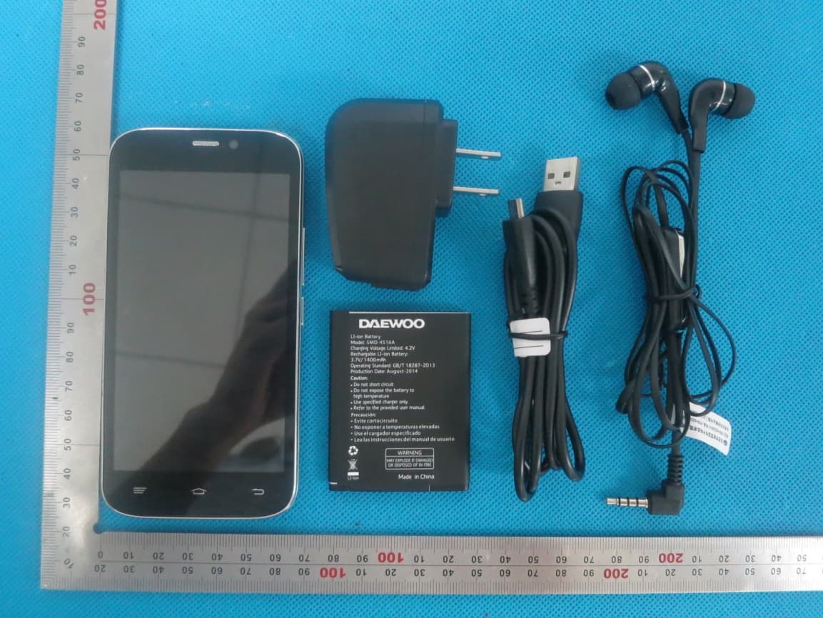
2AASJSMD-4516A
Aug 17, 2014Mobile Phone
Equipment Class
DTS - Digital Transmission System
2AASJSMD-4016A
Aug 16, 2014Mobile Phone
Equipment Class
DSS - Part 15 Spread Spectrum Transmitter
2AASJSMD-1770B
Aug 18, 2013Mobile Phone
Equipment Class
PCE - PCS Licensed Transmitter held to ear