2AAUCBTS28Wireless Stereo Speaker
Thermaltake Technology Co., Ltd.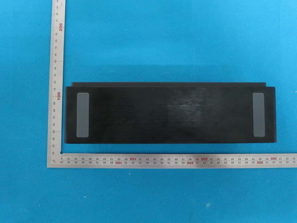
Click to zoom
Application Details
- Equipment Class
- DTS - Digital Transmission System
- Date of Grant
- Aug 31, 2014
- Application Purpose
- Original Equipment
- Date of Application
- Aug 31, 2014
- Equipment Note
- Wireless Stereo Speaker
- Frequency Range
- 2402.00000000 - 2480.00000000
- Country
- Taiwan
Documents & Files
Document Text
Text extracted from the exhibit documents filed with the FCC. Open a document above to read the original.
Users Manual
20140703 V1.1 1 User’s Manual Model: BTS28 With AUX In Function Wireless Stereo Speaker FCC ID:2AAUCBTS28 20140703 V1.1 2 A. Outlook and Controls Don’ts Do not place naked flames, such as lighted candles on or near the product. Do not place objects filled with liquids, such as vases on or near the product. Do not use or store this product in a place where it is subject to direct sunlight, heat, excessive dust or vibration. Do not use this product with wet hands. Do not clean this product with water or other liquids. Do not block or cover the slots and holes in the product. Do not push foreign objects into the slots or holes in the product. Do not attempt to open this product yourself. There are no user serviceable parts inside. Do not allow children access to plastic bags. Safety Instructions Before using this product, read and follow all warnings and instructions. This product is not intended for use by young children. Young children should be properly supervised. This product is intended for household use only and not for commercial or industrial use. Do not expose to dripping or splashing. No naked flame sources, such as lighted candles, should be placed on the product. Ventilation should not be impeded by covering ventilation openings with items such as newspapers, table cloths, curtains and the like. Make sure the unit is adjusted to a stable position. Damage caused by using this product in an unstable position or by failure to follow any other warning or precaution contained within this user manual will not be covered by warranty. Never remove the casing of this apparatus. Never place this apparatus on the other electrical equipment. We, suggest retaining the packaging in case for future transport of the product. WARNING: Never remove the casing of this apparatus. Never place this apparatus on the other electrical equipment. 20140703 V1.1 3 Notice If at any time in the future you should need to dispose of this product please note that: All batteries and accumulators need to be removed from this product (Removal of Waste Batteries and Accumulators). Always bring your product to a professional to remove the built-in battery. FCC Warning Statement Changes or modifications not expressly approved by the party responsible for compliance could void the user’s authority to operate the equipment. This device complies with part 15 of the FCC rules. Operation is subject to the following two conditions: (1) this device may not cause harmful interference, and (2) this device must accept any interference received, including interference that may cause undesired operation. 20140703 V1.1 4 B. Outlook and Controls 1 Metal Stand (Elevate Adjustable) 2 L & R Speakers 3 Center Bass Radiator 4 Main Power ON - OFF 5 Micro USB socket (DC 5V, 500mA Power Input) 6 AUX IN (3.5mm Jack, Stereo) 7 / Button 8 / Button 9 / Button 10 Button (Bluetooth Search) 11 Bluetooth LED (Blue, for Bluetooth Search / Pair) 12 Charge LED (Red, for Charge status) 13 MIC Position 14 AUX Mode LED (Red, for AUX In) C. About the rechargeable Battery & Charging This Bluetooth Speaker has an internal, non–user-replaceable battery. For best results, the first time you use this Bluetooth Speaker, let it charge for about 4 ~ 5 hours or until the charging LED indicator light from On to off which show you the battery is fully charged. For maintain the battery life and performance, if speaker isn’t used for a while, the battery might need to be recharged. Charge the battery at Front View Back View Top View 2 3 4 6 5 1 8 7 10 9 11 14 13 12 20140703 V1.1 5 least once every month. To recharge the built-in battery: 1. Connect the Bluetooth Speaker’s “Micro USB socket (5)” with the Computer’s USB port through USB cable. 2. The “Mode LED 2 (12)” will turn On in red, the battery is in charging. 3. The “Mode LED 2 (12)” will turn Off when the rechargeable battery is fully charged. 4. Disconnect the USB cable when it is done. D. Power ON and Pairing 1. Slide the “Power Switch (4)” to “ON” position to turn On the device. 2. A series of tones will sound and the “Bluetooth LED (11)” indicator is fast blinking in Blue. 3. Then, activate the Bluetooth function in your Bluetooth device (such as Mobile Phone or Personal Computer); the device will enter to Bluetooth searching mode automatically, if not, tap the relate selection to manually enter to searching mode. (refer to your device’s manual when necessary) 4. Your Bluetooth device should show “BTS28” in list, and then select it for pairing. Waiting for some seconds and you will see connected message as shown on your mobile device. (For some Bluetooth devices, you may need to input “0000” as pairing password) 5. If pairing is successful, a tones will sound and the “Bluetooth LED (11)” indicator will slow blinking each 3 ~ 4 seconds once. 6. Now, you can start to music play from the mobile device by it music player program. 7. Slide the “Power Switch (4)” to “OFF” position to turn Off the device when it is not in use. E. Disconnect from paired device 1. To disconnect with paired device and for better result, turn Off the Bluetooth Speaker by power OFF directly. 2. Or, you can choose “Disconnect” from Bluetooth paired device list on your mobile device. 3. In this case; the Bluetooth Speaker will turn back into “Searching / Pairing” mode in seconds, a series of tones will sound and the “Bluetooth LED (11)” indicator will fast blinking in Blue from slow. 4. Now, you can process for new mobile device pair or power Off the Bluetooth Speaker as you wanted. F. Auto reconnect with paired device 1. Every time you turn On the Bluetooth speaker power; it will firstly searching for the mobile device, which has been paired previously 20140703 V1.1 6 and still in record. The Bluetooth Speaker will reconnect this mobile device as priority if it is in Bluetooth searching device mode. 2. If not found in some seconds, the Bluetooth Speaker then is turn into new pairing mode inter…
Text truncated - open the document above for the full version.
External Photos
External Photos TOP VIEW OF EUT BOTTOM VIEW OF EUT FRONT VIEW OF EUT BACK VIEW OF EUT LEFT VIEW OF EUT RIGHT VIEW OF EUT
ID Label/Location Info
FCC ID Label Location FCC ID:2AAUCBTS28
Internal Photos
Internal Photos OPEN VIEW OF EUT INTERNAL VIEW OF EUT-1 BT Antenna INTERNAL VIEW OF EUT-2 INTERNAL VIEW OF EUT-3
Test Report
Report No.: AGC00902140701FE08 Page 1 of 49 FCC Test Report Report No.: AGC00902140701FE08 FCC ID : 2AAUCBTS28 APPLICATION PURPOSE : Original Equipment PRODUCT DESIGNATION : Wireless Stereo Speaker BRAND NAME : LUXA2 MODEL NAME : GROOVY A (BTS28) CLIENT : Thermaltake Technology Co., Ltd. DATE OF ISSUE : Aug.07, 2014 STANDARD(S) : FCC Part 15 Rules REPORT VERSION : V1.0 Attestation of Global Compliance (Shenzhen) Co., Ltd CAUTION: This report shall not be reproduced except in full without the written permission of the test laboratory and shall not be quoted out of context. Report No.: AGC00902140701FE08 Page 2 of 49 Report Revise Record Report Version Revise Time Issued Date Valid VersionNotes V1.0 / Aug.07, 2014 Valid Original Report Report No.: AGC00902140701FE08 Page 3 of 49 TABLE OF CONTENTS 1. VERIFICATION OF COMPLIANCE......................................................................................................... 5 2.GENERAL INFORMATION ...................................................................................................................... 6 2.1PRODUCT DESCRIPTION ............................................................................................................... 6 2.2 RELATED SUBMITTAL(S)/GRANT(S) ............................................................................................. 6 2.3TEST METHODOLOGY .................................................................................................................... 6 2.4 TEST FACILITY ................................................................................................................................ 6 2.5 SPECIAL ACCESSORIES ................................................................................................................ 6 2.6 EQUIPMENT MODIFICATIONS ....................................................................................................... 7 2.7 MEASUREMENT UNCERTAINTY ................................................................................................... 7 3. SYSTEM TEST CONFIGURATION ......................................................................................................... 8 3.1 CONFIGURATION OF TESTED SYSTEM ....................................................................................... 8 3.2 EQUIPMENT USED IN TESTED SYSTEM ...................................................................................... 8 3.3. SUMMARY OF TEST RESULTS ..................................................................................................... 8 4. DESCRIPTION OF TEST MODES .......................................................................................................... 9 5. ANTENNA REQUIREMENT .................................................................................................................... 9 5.1. STANDARD APPLICABLE .............................................................................................................. 9 5.2. TEST RESULT ................................................................................................................................ 9 6. TEST FACILITY ..................................................................................................................................... 10 7. RADIATED EMISSION .......................................................................................................................... 11 7.1 MEASUREMENT PROCEDURE .................................................................................................... 11 7.2 TEST SETUP .................................................................................................................................. 12 7.3 LIMITS AND MEASUREMENT RESULT ........................................................................................ 13 7.4 TEST RESULT (WORST MODULATION: GFSK) ................................................................................ 13 8. BAND EDGE EMISSION ....................................................................................................................... 26 8.1. MEASUREMENT PROCEDURE ................................................................................................... 26 8.2. TEST SET-UP ............................................................................................................................... 26 8.3. TEST RESULT .............................................................................................................................. 27 9. 6DB BANDWIDTH ................................................................................................................................ 31 9.1. TEST PROCEDURE ...................................................................................................................... 31 9.2. SUMMARY OF TEST RESULTS/PLOTS ...................................................................................... 31 10. CONDUCTED OUTPUT POWER ....................................................................................................... 33 10.1. MEASUREMENT PROCEDURE ................................................................................................. 33 10.2. TEST SET-UP (BLOCK DIAGRAM OF CONFIGURATION) ........................................................ 33 10.3. LIMITS AND MEASUREMENT RESULT ..................................................................................... 34 11. MAXIMUM CONDUCTED OUTPUT POWER SPECTRAL DENSITY ................................................ 36 11.1 MEASUREMENT PROCEDURE .................................................................................................. 36 Report No.: AGC00902140701FE08 Page 4 of 49 11.2 TEST SET-UP (BLOCK DIAGRAM OF CONFIGURATION) ......................................................... 36 11.3 LIMITS AND MEASUREMENT RESULT ...................................................................................... 36 12. FCC LINE CONDUCTED EMISSION TEST ....…
Text truncated - open the document above for the full version.
Test Setup Photos
APPENDIX IV PHOTOGRAPHS OF TEST SETUP FCC LINE CONDUCTED EMISSION TEST SETUP FCC RADIATED EMISSION TEST SETUP
Contact Information
Applicant
Michael Lin
Test Firm
Attestation of Global Compliance Shenzhen Co. Ltd.Forrest Lei
Technical Specifications
| # | Rule Parts | Frequency Range | Power Output |
|---|---|---|---|
| 1 | 15C | 2.40 GHz - 2.48 GHz | 2.00 mW |
Other Applications from Thermaltake Technology Co., Ltd.
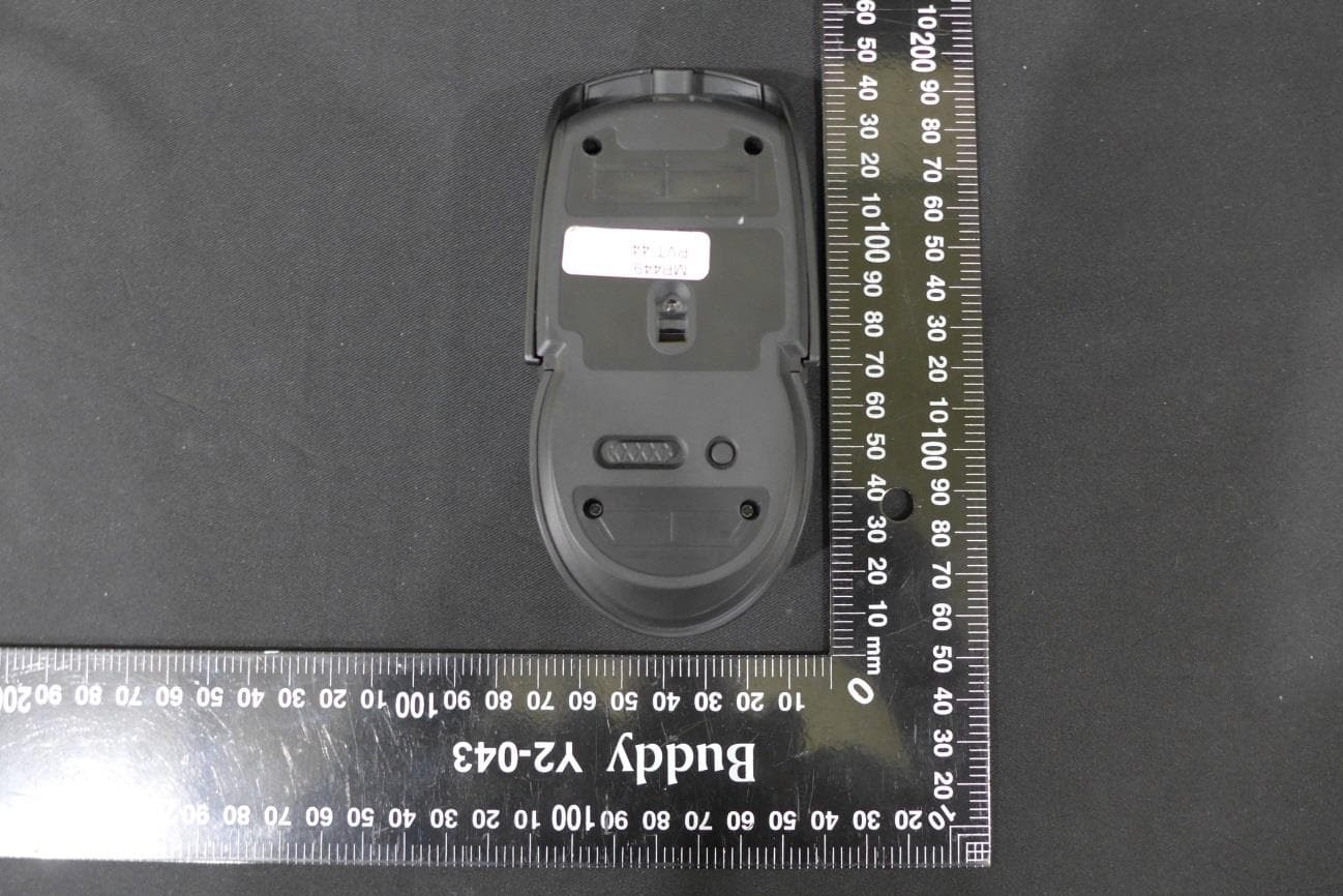
2AAUCGMOTMF
Jul 08, 2020Argent M5 Wireless RGB Gaming Mouse
Equipment Class
DXX - Part 15 Low Power Communication Device Transmitter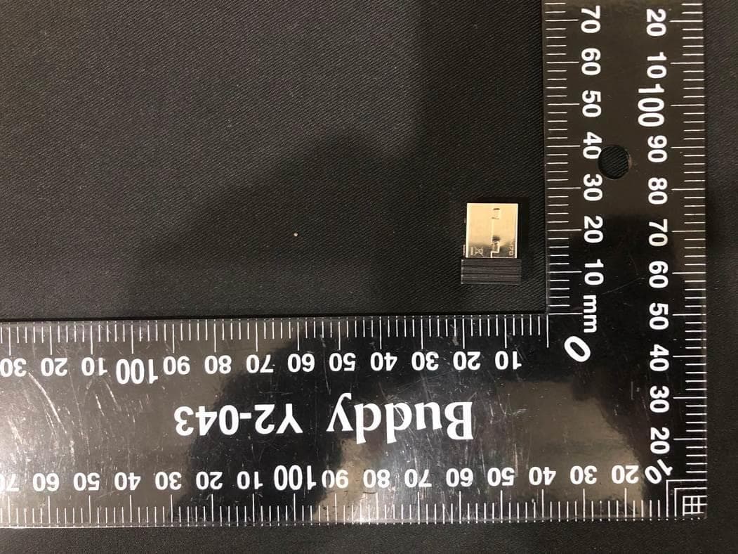
2AAUCGMOTMFRX
Jul 08, 2020Argent M5 Wireless Dongle
Equipment Class
DXX - Part 15 Low Power Communication Device Transmitter
2AAUCKBPZP
Mar 15, 2015POSEIDON Z PLUS
Equipment Class
DTS - Digital Transmission System
2AAUCMGBLKAPBBBK
Feb 25, 2015Contour
Equipment Class
DSS - Part 15 Spread Spectrum Transmitter
2AAUCPOWPCPCP2BK
Dec 21, 2014TX-P2 10000mAh Wireless Charging Power Bank
Equipment Class
DCD - Part 15 Low Power Transmitter Below 1705 kHz