2AB7S-YK5135K00MONITOR WITH RECEIVER
Soundmax Electronics Limited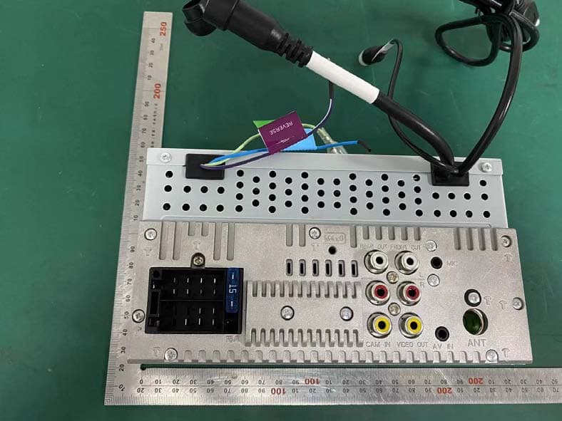
Click to zoom
Application Details
- Equipment Class
- DSS - Part 15 Spread Spectrum Transmitter
- Date of Grant
- Jan 14, 2020
- Application Purpose
- Original Equipment
- Date of Application
- Jan 14, 2020
- Equipment Note
- MONITOR WITH RECEIVER
- Frequency Range
- 2402.00000000 - 2480.00000000
- Company
- Soundmax Electronics Limited
- Country
- China
Documents & Files
Document Text
Text extracted from the exhibit documents filed with the FCC. Open a document above to read the original.
Users Manual
DMX4 7 07 S B5H-0358-xx (E)© 2020 JVCKENWOOD Corporation MONITOR WITH RECEIVER INSTRUCTION MANUAL • Updated information (the latest Instruction Manual, etc.) is available from <http://w w w.kenwood.com/cs/ce/>. Playable Media and Files........................................45 27 2 Contents Before Use 3 Precautions ...................................................................3 How to read this manual .........................................3 Basic Operations 4 Functions of the Buttons on the Front Panel ...4 Turning on the Unit ...................................................4 Initial S ettings ..............................................................5 Adjusting the volume ...............................................6 Touch screen operations .........................................6 HOME screen descriptions ......................................7 Source selection screen descriptions ..................7 Source control screen descriptions ....................9 MENU screen .............................................................. List screen ...................................................................10 APPS-Android Auto™/ Apple CarPlay 11 Apple CarPlay Operation .......................................11 Android Auto™ Operation .....................................12 USB 13 Connecting a USB device ......................................13 USB Basic Operation ................................................13 Sear ch Operation ......................................................15 Radio 16 Radio Basic Operation ............................................16 Memory Operation ..................................................17 Selecting Operation ................................................17 Traffic Information (FM only) ...............................18 Radio Setup ................................................................18 Bluetooth Control 19 Information for using Bluetooth® devices .......19 Register from the Bluetooth device ...................20 Bluetooth Setup ........................................................20 P laying Bluetooth Audio Device .........................21 U sing Hands-Free Unit ............................................23 Other External Components 27 View Camera .............................................................. External audio/video players—AV-IN ...............28 Setting Up 29 Monitor Screen Setup .............................................29 System Setup .............................................................29 User Interface Setup ................................................30 Special Setup .............................................................30 Display Setup .............................................................31 A V Setup ......................................................................32 Controlling Audio 33 Speaker/ X’over setup .............................................33 Controlling General Audio ....................................34 Equalizer Control ......................................................35 Volume Offset ............................................................ 36 Sound Effect ...............................................................36 Listening Position/ DTA ..........................................37 Remote control 38 Functions of the Remote control Buttons .......38 Connection/Installation 39 Before Installation ....................................................39 Installing the unit .....................................................39 Troubleshooting 44 Problems and Solutions .........................................44 Error Messages ..........................................................44 Appendix 45 Specifications .............................................................46 About this Unit ..........................................................48 9 Before Use Before Use Precautions # WARNINGS Ñ To prevent injury or fire, take the following precautions: • To prevent a short circuit, never put or leave any metallic objects (such as coins or metal tools) inside the unit. • Do not watch or fix your eyes on the unit’s display when you are driving for any extended period. • If you experience problems during installation, consult your KENWOOD dealer. Ñ Precautions on using this unit • When you purchase optional accessories, check with your KENWOOD dealer to make sure that they work with your model and in your area. • You can select language to display menus, audio file tags, etc. See User Interface Setup (P.30). • Th e Radio Data System or Radio Broadcast Data System feature won’t work where the service is not supported by any broadcasting station. Ñ Protecting the monitor • To protect the monitor from damage, do not operate the monitor using a ball point pen or similar tool with the sharp tip. Ñ Cleaning the unit • If the faceplate of this unit is stained, wipe it with a dry soft cloth such as a silicon cloth. If the faceplate is stained badly, wipe the stain off with a cloth moistened with neutral cleaner, then wipe it again with a clean soft dry cloth. NOTE • Applying spray cleaner directly to the unit may affect its mechanical parts. Wiping the faceplate with a hard cloth or using a volatile liquid such as thinner or alcohol may scratch the surface or erase screened print. Ñ How To Reset Your Unit • If the unit or the connected unit fails to operate properly, reset the unit.1 Press the <Reset> button.The unit returns to factory settings. NOTE • Disconnect the USB device before pressing the <Reset> button. Pressing the <Reset> button with the USB device connected can damage the data stored in the USB device. For how to disconnect the USB device, see Disconnect the USB device (P.13). • When the unit is turned on after resetting, the Initial SETUP screen appears. See Initial setup (P.6). How to read this manual • The screens and panels shown in this manual are examples used to provide clear explanations of the operations…
Text truncated - open the document above for the full version.
Users Manual
Other External Components 27 English Other External Components View Camera NOTE • To connect a camera, see . • To use a rear view camera, a REVERSE lead connection is required. • Th e rear view screen is displayed when you shift the gear to the reverse (R) position. Ñ Display the camera screen 1 Press the [MENU] button. hhMENU screen appears. 2 Touch []. hhView camera screen appears. 3 Adjust each item as follows. 1 1 Camera off Touch to exit the camera screen. Ñ Camera Setup 1 Press the [MENU] button. hhMENU screen appears. 2 Touch []. hhSETUP Menu screen appears. 3 Touch [Camera]. hhCamera screen appears. 4 Set each item as follows. ■Parking Guidelines You can display parking guidelines to enable easier parking when you shift the gear to the reverse (R) position. Default is “ON”. ■Guidelines SETUP I f you select [ON] for [Parking Guidelines], adjust the parking guidelines. See To adjust the parking guidelines (P.36). [] Other External Components 28 External audio/video players— AV- IN 1 Connect an external component to the AV-IN input terminal. 2 Select [AV-IN] as the source. 3 Turn on the connected component and start playing the source. To adjust the parking guidelines NOTE • Install the rear view camera in the appropriate position according to the instructions supplied with the rear view camera. • When adjusting the parking guidelines, make sure to use the parking brake to prevent the car from moving. 1 Touch [ON] of [Parking Guidelines] in the Camera screen. 2 Touch [Guidelines SETUP] in the Camera screen. 3 Adjust the parking guidelines by selecting the mark. 4 Adjusting the position of the selected mark. A B C D Make sure that A and B are horizontally parallel, and that C and D are the same length. NOTE • Touch [Initialize] and after touch [Ye s] to set all the marks to the initial default position. Setting Up 29 English Setting Up Monitor Screen Setup You can adjust image quality in video screen. 1 Press the [MENU] button. hhMENU screen appears. 2 Touch []. hhScreen Control screen appears. 3 Adjust each item as follows. ■Contrast / Brightness / Colour / Tint Adjusts each item. NOTE • Adjusting items are different depending on the current source. System Setup NOTE • Each operation in this section can be started from the multi function menu. 1 Press the [MENU] button. hhMENU screen appears. 2 Touch []. See the following section for each setting. [] Setting Up 30 User Interface Setup You can setup user interface parameters. 1 Press the [MENU] button. hhMENU screen appears. 2 Touch []. hhSETUP screen appears. 3 Touch [User Interface]. hhUser Interface screen appears. 4 Set each item as follows. ■Beep T urns the key touch tone on or off. Default is “OFF”. ■Language Selects a language. ■Steering Remote Controller Sets the desired function in the steering remote controller. (Contact your KENWOOD dealer for details.) ■Clock Adjust Adjust the dat e and time manually. ( P.7) Special Setup You can setup Special parameters. 1 Press the [MENU] button. hhMENU screen appears. 2 Touch []. hhSETUP screen appears. 3 Touch [Special]. hhSpecial screen appears. 4 Set each item as follows. ■DEMO Set the demonstration mode. Default is “ON”. ■Sof tware Information Check the software version of this unit. ( P.34) ■Open Source Licenses Displays the open source licenses. ■Initialize Touch [Initialize] and then touch [Ye s] to set all the settings to the initial default settings. Ñ Software Information Check the software version of this unit. 1 Touch [Software Information] in the Special screen. 2 Confirm the software version. [] Setting Up 31 English Display Setup 1 Press the [MENU] button. hhMENU screen appears. 2 Touch []. hhSETUP screen appears. 3 Touch Display. hhDisplay screen appears. 4 Set each item as follows. ■Dimmer Select dimmer mode. OFF: The display and buttons do not dim. ON: The display and buttons dim. SYNC (Default): Turns the dimmer function on or off when the vehicle light control switch is turned on or off. ■Screen Adjustment Displays the Screen Adjustment screen. ■Background Changing background image or color. ÑChange background image or color 1 Touch [Background] in the Display screen. 2 Select an image. [] Setting Up 32 To register original image You can load an image from the connected USB device and set it for the background image. Before operating this procedure, it is necessary to connect the device which has the image to load. 1 Touch [User1 Select] or [User2 Select] in the Background screen. 2 Select the image to load. 3 Touch [Enter]. hhThe selected image is loaded and the display returns to the Background screen. NOTE • Touching [] rotates counter clockwise. • Touching [ ] rotates clockwise. • Picture files: JPEG (.jpg, .jpeg), PNG (.png), BMP (.bmp) AV Setup You can set AV parameters. 1 Press the [MENU] button. hhMENU screen appears. 2 Touch []. hhSETUP screen appears. 3 Touch [AV]. hhAV screen appears. 4 Set each item as follows. ■AV-OUT Specify whether to output the current source signal from the AV OUTPUT terminal. “ON”/ “OFF” (Default) NOTE • Images can be output only from the AV IN and USB (video file) source. • If display of the rear view camera image is selected when the AV-IN source is being played, no image is output from the AV OUTPUT terminal. ■CarPlay Sidebar Select the position of the control bar (left or right) shown on the touch panel. “Left” (Default)/ “Right” NOTE • The setting is available when an iPhone is disconnected. ■AV Color Adjust You can adjust image quality in video screen. NOTE • Adjusting items are different depending on the current source. Controlling Audio 33 English Controlling Audio NOTICE • Each operation in this section can be started from the multi function menu. You can adjust the various settings such as audio balance or subwoofer level. 1 Press the [MENU] button. hhMENU screen appears. 2 Touch []. See the following section for each setting. Speaker/ X’over setup 1 Press the [MENU] button. hhMENU screen appears. 2 Touch []. hhAudio scre…
Text truncated - open the document above for the full version.
Attestation Statements
Soundmax Electronics Limited I, the signer, Roy Wu The differences between these models are shown in the table below. All models are electrically identical. Model Name Brand Remark DMX4707S KENWOOD Base model: AM/FM//USB/iPhone/Bluetooth, has SiriusXM feature. DMX47S KENWOOD DMX4707S and DMX47S features are exactly same, just sales channels are different. KW-M560BT JVC KW-M560BT and DMX4707S difference is SiriusXM optional(depends on selling region)Using JVC GUI. KW-M56BT JVC KW-M56BT and DMX4707S difference is using JVC GUI. Item Name :MONITOR WITH RECEIVER Model Number: DMX4707S Additional Model: DMX47S, KW-M560BT, KW-M56BT FCC ID: 2AB7S-YK5135K00 <Signature> Name: Roy Wu Title: Engineer Company: Soundmax Electronics Limited
External Photos
External photos External photos External photos External photos
ID Label/Location Info
TOP LABEL For Model : DMX47S K (KENWOOD BRAND) **SMPOXXXX** P/NO:706-DMX502001-KW-XX 80 x 45mm White Background / Black Lettering PET 材质 Document Size Colour Material DMX47S K TOP LABEL SCALE:1/1 Month: Month plus 5. Exsample, July is 12, is . Year:1 digit of A.D. plus 5. Exsample, 2013 is 8, 2020is 5. Factry code: In this case "0" (zero). Serial number from 0001 to 9999 in a Month. 07500001 Feb 07 DATE:2019-12-23 IC:CAN ICES-3 (B)/NMB-3(B)
ID Label/Location Info
TOP LABEL For Model : DMX4707S K (KENWOOD BRAND) **SMPOXXXX** P/NO:706-DMX502001-KW-XX 80 x 45mm White Background / Black Lettering PET 材质 Document Size Colour Material DMX4707S K TOP LABEL SCALE:1/1 Month: Month plus 5. Exsample, July is 12, is . Year:1 digit of A.D. plus 5. Exsample, 2013 is 8, 2020is 5. Factry code: In this case "0" (zero). Serial number from 0001 to 9999 in a Month. Feb 07 DATE:2019-12-23 07500001 IC:CAN ICES-3 (B)/NMB-3(B)
ID Label/Location Info
TOP LABEL For Model : KW-M56BT K (JVC BRAND) **SMPOXXXX** P/NO:706-DMX502001-JC-XX 80 x 45mm White Background / Black Lettering PET 材质 Document Size Colour Material KW-M56BT K TOP LABEL SCALE:1/1 Month: Month plus 5. Exsample, July is 12, is . Year:1 digit of A.D. plus 5. Exsample, 2013 is 8, 2020is 5. Factry code: In this case "0" (zero). Serial number from 0001 to 9999 in a Month. Feb 07 DATE:2019-12-23 07500001 IC:CAN ICES-3 (B)/NMB-3(B)
ID Label/Location Info
TOP LABEL For Model : KW-M560BT K (JVC BRAND) **SMPOXXXX** P/NO:706-DMX502001-JC-XX 80 x 45mm White Background / Black Lettering PET 材质 Document Size Colour Material KW-M560BT K TOP LABEL SCALE:1/1 Month: Month plus 5. Exsample, July is 12, is . Year:1 digit of A.D. plus 5. Exsample, 2013 is 8, 2020is 5. Factry code: In this case "0" (zero). Serial number from 0001 to 9999 in a Month. Feb 07 DATE:2019-12-23 07500001 IC:CAN ICES-3 (B)/NMB-3(B)
Internal Photos
Internal photos Internal photos Internal photos Internal photos Internal photos Internal photos Internal photos
RF Exposure Info
FCC ID: 2AB7S-YK5135K00 EST Technology Co. ,Ltd Report No. ESTE-R1912096 Page 1 of 4 FCC 47 CFR MPE REPORT Soundmax Electronics Limited MONITOR WITH RECEIVER Model Number: DMX4707S Additional Model: DMX47S, KW-M560BT, KW-M56BT FCC ID: 2AB7S-YK5135K00 Prepared for: Soundmax Electronics Limited 17/F EU YANG SANG TOWER, 11-15 CHATHAM ROAD, T.S.T, KOWLOON,Hong Kong, China Prepared By: EST Technology Co., Ltd. Chilingxiang, Qishantou, Santun, Houjie, Dongguan, Guangdong, China Tel: 86-769-83081888-808 Report Number: ESTE-R1912096 Date of Test: Dec. 02~Dec. 19, 2019 Date of Report: Dec. 24, 2019 FCC ID: 2AB7S-YK5135K00 EST Technology Co. ,Ltd Report No. ESTE-R1912096 Page 2 of 4 Maximum Permissible Exposure 1. Applicable Standards Systems operating under the provisions of this section shall be operated in a manner that ensures that the public is not exposed to radio frequency energy level in excess limit for maximum permissible exposure. In accordance with 47 CFR FCC Part 2 Subpart J, section 2.1091 this device has been defined as a mobile device whereby a distance of 0.2m normally can be maintained between the user and the device. 1.1. Limits for Maximum Permissible Exposure (MPE) (a) Limits for Occupational/Controlled Exposure Frequency Range (MHz) Electric Field Strength (E) (V/m) Magnetic Field Strength (H) (A/m) Power Density (S) (mW/cm 2 ) Averaging Times ︱E︱ 2 ,︱H︱ 2 or S (minutes) 0.3-3.0 614 1.63 (100)* 6 3.0-30 1842/f 4.89/f (900/f)* 6 30-300 61.4 0.163 1.0 6 300-1500 F/300 6 1500-10000 5 6 (b) Limits for General Population / Uncontrolled Exposure Frequency Range (MHz) Electric Field Strength (E) (V/m) Magnetic Field Strength (H) (A/m) Power Density (S) (mW/cm 2 ) Averaging Times ︱E︱ 2 ,︱H︱ 2 or S (minutes) 0.3-1.34 614 1.63 (100)* 30 1.34-30 824/f 2.19/f (180/f)* 30 30-300 27.5 0.073 0.2 30 300-1500 F/1500 30 1500-10000 1.o 30 Note: f=frequency in MHz; *Plane-wave equivalent power density FCC ID: 2AB7S-YK5135K00 EST Technology Co. ,Ltd Report No. ESTE-R1912096 Page 3 of 4 1.2. MPE Calculation Method E (V/m) = d G×P×30 Power Density: Pd (W/m 2 ) = 377 E 2 E = Electric Field (V/m) P = Peak RF output Power (W) G = EUT Antenna numeric gain (numeric) d = Separation distance between radiator and human body (m) The formula can be changed to Pd = 2 d×377 G×P×30 From the peak EUT RF output power, the minimum mobile separation distance, d=0.2m, as well as the gain of the used antenna, the RF power density can be obtained FCC ID: 2AB7S-YK5135K00 EST Technology Co. ,Ltd Report No. ESTE-R1912096 Page 4 of 4 2. Conducted Power Result Mode Frequency (MHz) Peak output power (dBm) Peak output power (mW) Target power (dBm) Antenna gain (dBi) (Linear) BT GFSK 2402 3.20 2.089 3 ±1 0 1 2441 3.36 2.168 3±1 0 1 2480 3.77 2.382 3±1 0 1 BT 8-DPSK 2402 2.49 1.774 2 ±1 0 1 2441 2.62 1.828 2±1 0 1 2480 3.00 1.995 3±1 0 1 3. Calculated Result and Limit Mode Target power (dBm) Antenna gain Power Density (S) (mW/cm 2 ) Limited of Power Density (S) (mW/cm 2 ) Test Result (dBi) (Linear) GFSK 4 0 1 0.0005 1 Compiles 8-DPSK 4 0 1 0.0005 1 Compiles End of Test Report
Test Report
FCC ID: 2AB7S-YK5135K00 EST Technology Co., Ltd Report No.ESTE-R1912095 Page 1 of 73 FCC PART 15C TEST REPORT FOR CERTIFICATION On Behalf of Soundmax Electronics Limited MONITOR WITH RECEIVER Model Number: DMX4707S Additional Model: DMX47S, KW-M560BT, KW-M56BT FCC ID: 2AB7S-YK5135K00 Prepared for: Soundmax Electronics Limited 17/F EU YANG SANG TOWER, 11-15 CHATHAM ROAD, T.S.T, KOWLOON,Hong Kong, China Prepared By: EST Technology Co., Ltd. Chilingxiang, Qishantou, Santun, Houjie, Dongguan, Guangdong, China Tel: 86-769-83081888-808 Report Number: ESTE-R1912095 Date of Test: Dec. 02~Dec. 19, 2019 Date of Report: Dec. 24, 2019 FCC ID: 2AB7S-YK5135K00 EST Technology Co., Ltd Report No.ESTE-R1912095 Page 2 of 73 TABLE OF CONTENTS Description Page TEST REPORT VERIFICATION ........................................................................................................................ 3 1. GENERAL INFORMATION ................................................................................................................. 5 1.1. Description of Device (EUT) ........................................................................................................... 5 1.2. Antenna Information ........................................................................................................................ 5 1.3. Difference between Model Numbers ................................................................................................ 5 2. SUMMARY OF TEST ......................................................................................................................... 6 2.1. Summary of test result ...................................................................................................................... 6 2.2. Test Facilities .................................................................................................................................... 7 2.3. Measurement uncertainty ................................................................................................................. 8 2.4. Assistant equipment used for test ..................................................................................................... 8 2.5. Block Diagram .................................................................................................................................. 8 2.6. Test mode ......................................................................................................................................... 9 2.7. Channel List .................................................................................................................................... 10 2.8. Power Setting of Test Software ...................................................................................................... 10 2.9. Test Equipmen ................................................................................................................................ 11 3. MAXIMUM PEAK OUTPUT POWER ................................................................................................. 12 3.1. Limit ............................................................................................................................................... 12 3.2. Test Setup ....................................................................................................................................... 12 3.3. Spectrum Analyzer Setting ............................................................................................................. 12 3.4. Test Procedure ................................................................................................................................ 12 3.5. Test Result ...................................................................................................................................... 13 4. 20 DB BANDWIDTH ...................................................................................................................... 18 4.1. Limit ............................................................................................................................................... 18 4.2. Test Setup ....................................................................................................................................... 18 4.3. Spectrum Analyzer Setting ............................................................................................................. 18 4.4. Test Procedure ................................................................................................................................ 18 4.5. Test Result ...................................................................................................................................... 19 5. CARRIER FREQUENCY SEPARATION .............................................................................................. 24 5.1. Limit ............................................................................................................................................... 24 5.2. Test Setup ....................................................................................................................................... 24 5.3. Spectrum Analyzer Setting ............................................................................................................. 24 5.4. Test Procedure ................................................................................................................................ 24 5.5. Test Result ...................................................................................................................................... 25 6. NUMBER OF HOPPING CHANNEL .................................................................................................. 30 6.1. Limit ............................................................................................................................................... 30 6.2. Test Setup ..............................................…
Text truncated - open the document above for the full version.
Test Setup Photos
Radiated Test: Below 1GHz Radiated Test: Above 1GHz
Contact Information
Applicant
Roy Wu
Test Firm
EST Technology Co., Ltd.Iceman Hu
[email protected]+86 0769-83081888
Technical Specifications
| # | Rule Parts | Frequency Range | Power Output |
|---|---|---|---|
| 1 | 15C | 2.40 GHz - 2.48 GHz | 2.40 mW |
Other Applications from Soundmax Electronics Limited
2AB7S-YL5077K00
Sep 11, 2024MONITOR WITH RECEIVER
Equipment Class
DSS - Part 15 Spread Spectrum Transmitter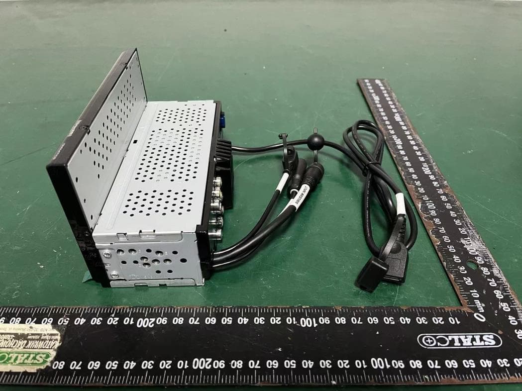
2AB7S-YL5070K00
Jan 11, 2024MONITOR WITH RECEIVER
Equipment Class
DSS - Part 15 Spread Spectrum Transmitter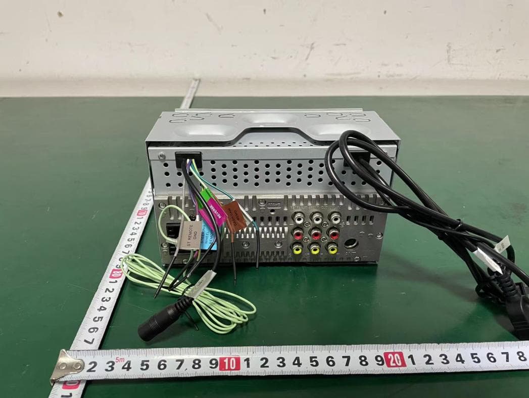
2AB7S-YL5045K00
Apr 09, 2023MONITOR WITH RECEIVER
Equipment Class
DSS - Part 15 Spread Spectrum Transmitter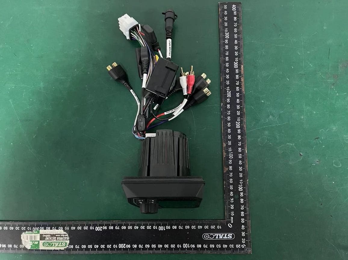
2AB7S-YL5043K00
Mar 28, 2023DIGITAL MEDIA RECEIVER
Equipment Class
DSS - Part 15 Spread Spectrum Transmitter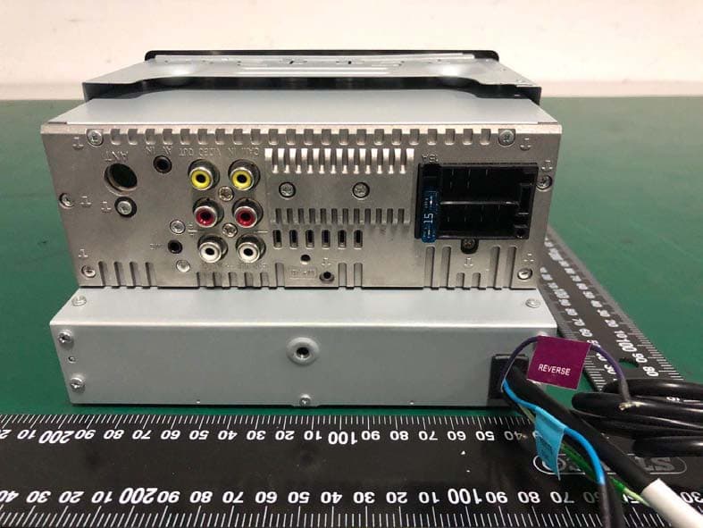
2AB7S-YK5137K00
May 20, 2020MONITOR WITH DVD RECEIVER
Equipment Class
DSS - Part 15 Spread Spectrum Transmitter