2AB8795311Wireless Device
Iconnect
Click to zoom
Application Details
- Equipment Class
- DTS - Digital Transmission System
- Date of Grant
- Mar 17, 2020
- Application Purpose
- Original Equipment
- Date of Application
- Mar 17, 2020
- Equipment Note
- Wireless Device
- Frequency Range
- 2412.00000000 - 2462.00000000
- Company
- Iconnect
- Country
- Taiwan
Documents & Files
Document Text
Text extracted from the exhibit documents filed with the FCC. Open a document above to read the original.
Users Manual
1 N2QF User manual 2 FCC STATEMENT This equipment has been tested and found to comply with the limits for a Class B digital device, pursuant to part 15 of the FCC Rules. Theselimits are designed to provide reasonable protection against harmful interference in a residential installation. This equipment generates, uses and can radiate radio frequency energy and, if not installed and used in accordance with the instructions, may cause harmful interference to radio communications. However, there is no guarantee that interference will not occur in a particular installation. If this equipment does cause harmful interference to radio or television reception, which can be determined by turning the equipment off and on, the user is encouraged to try to correct the interference by one or more of the following measures: •Reorient or relocate the receiving antenna. •Increase the separation between the equipment and receiver. •Connect the equipment into an outlet on a circuit different from that to which the receiver is connected. •Consult the dealer or an experienced radio/ TV technician for help. This device complies with part 15 of the FCC Rules. Operation is subject to the following two conditions: 1)This device may not cause harmful interference. 2)This device must accept any interference received, including interference that may cause undesired operation. Any changes or modifications not expressly approved by the party responsible for compliance could void the user’s authority to operate the equipment. NOTE: 1.THE MANUFACTURER IS NOT RESPONSIBLE FOR ANY RADIO OR TV INTERFERENCE CAUSED BY UNAUTHORIZED MODIFICATIONS TO THIS EQUIPMENT. SUCH MODIFICATIONS COULD VOID THE USER’S AUTHORITY TO OPERATE THE EQUIPMENT. 2.The antenna(s) used for this transmitter must not be co-located of operating in conjunction with any other antenna or transmitter. This device complies with FCC radiation exposure limits set forth for an uncontrolled environment. Ln order to avoid the possibility of exceeding the Fcc radio frequency exposure limits, human proximity to the antenna shall not be less than 20cm (8inches) during normal operation. 3 FCC RF Radiation Exposure Statement This equipment complies with FCC RF radiation exposure limits set forth for an uncontrolled environment. This device and its antenna must not be co-located or operating in conjunction with anyother antenna or transmitter. “To comply with FCC RF exposure compliance requirements, this grant is applicable to only Mobile Configurations. The antennas used for this transmitter must be installed to provide a separation distance of at least 20 cm fromall persons and must not be co-located or operating in conjunction with any other antenna or transmitter.” CE Mark Warning This is a class B product. In a domestic environment, this product may cause radio interference, in which case the user may be required to take adequate measures. 4 CONTENTS Product introduction 1.Product interface introduction 2.Product function brief ※APBridgeMode ※ClientBridgeMode ※WDS Mode How to ApplyN2QF 3.How to InstallN2QFFDevice 4.How to ConfigureN2QF 4-1.Howto Setup yourPC 4-2.N2QF's Function Settings ※APBridgeMode Setting ※ClientBridgeMode Setting ※WDS Mode Setting Product introduction 1.Product interface introduction 5 Dashboard:Showthe current status information about theN2QF. Wizard:Configure yourN2QFFquickly and work it. Network:Configure Local Network IP,Subnet Mask,etc., andenable DHCP Server. Wireless:Setup WirelessSettingson yourN2QF. System: Important settings for related information with hardware. 2.Product function brief There are 3 operation Modes, AP Bridge Mode, Client Bridge Mode, and WDS Mode can be selected 6 ※APBridgeMode:The AP Mode is the most commonlyand widely used mode of operation. Let mobile devices such as smart phones, tablets,etc.access Internet. ※ClientBridgeMode:In Client Mode, theN2QFFis receive other wireless signals; the unlimited device only be used by connecting to theN2QF. ※WDS Mode:Provides service operate in one of three modes; WDS AP Mode, WDS Client Mode, or WDS Repeater Mode.Please refer to the detailed instructions in section 4-2. 1)WDS AP Mode:WDS AP Mode is anaccess point, but it onlywork on other WDS Mode 2)WDS ClientMode:WDS Client, in which WDS APs communicate with WDS Client to access them 7 3)WDS Repeater Mode:WDS repeater, in which WDS Apscommunicate with each other and with WDS Client. And extend the original wireless signal. How to ApplyN2QF 3.How to InstallN2QFDevice 1)Connect the PC in PoE LAN port or normal LAN portofN2QF. 2)Connect the power toN2QF. 8 4.How to ConfigureN2QF 4-1.How to Setup your PC Follow the stepsbelow to configure in Windows OS. 1)Press on theWindows KeyandXonyour Keyboard. 2)On the menu that appearsandclickNetworkConnections. 3)On the Network Connectionsscreen;Right click on Local Area Connection and clickProperties(if your Windows OS isWindows 10, clickChange adapter settings 9 first and follow upthe step) 4)Click Internet Protocol Version 4 (TCP/IP) then click Properties 10 5)Set your PC’s IP address manually to 192.168.1.2. And set Subnet mask to 255.255.255.0( or other address in the same subnet). 11 6)Click OK to save and apply your settings. 12 Now,you can run the Ping command in the command prompt. 7)Click onSearch Icon;Typingcmd andclick on theCommand Prompt Icon. 8)On theCommand Promptscreen; Typing “ping 192.168.1.1” 13 If the result is similar to the one shown below, it means the connectionsuccess.If the result is not similar to the one shown below, back to set PC’s address steps. 9)After connect success, open a web-browser and type in the default address http://192.168.1.1 in the addressof the browser. 10) A login window will display,and enter the default password "admin" to login. 14 4-2.N2QF's Function Settings Please follow the teaching stepstoconfigure. 1)Open Wizard Settings by clicking onWizardon the left control menu. 15 Country Code:Please select your country code to ensurethat the r…
Text truncated - open the document above for the full version.
Cover Letter(s)
Iconnect Add: No.9, Aly. 58, Ln. 112, Ruiguang Rd., Neihu Dist., Taipei City,Taiwan Tel: 886‐2‐27968477 Fax: 886‐2‐27968478 Email: [email protected] DECLARATION OF SIMILARITY Date: 2020-1-22 FEDERAL COMMUNICATIONS COMMISSION Authorization and Evaluation Division 7435 Oakland Mills Road Columbia, MD 21046 Dear Sir or Madam: We, Iconnect, hereby declare that the product: Wireless Device, FCC ID: 2AB8795311. model: N2Q,N2QP,N2QS,N2QC,N2QCP,N2QFP,N2QSP,N5Q,N5QP,N5QS,N5QF,N5QC,N5QCP,N5QSP, N5QFP,N25Q,N25QP,N25QS,N25QF,N25QC,N25QCP,N25QSP,N25QFP,N52Q,N52QP,N52QS, N52QF,N52QC,N52QCP,N52QSP,N52QFP,N2M,N2MP,N2MS,N2MF,N2MC,N2MCP,N2MSP, N2MFP,N5M,N5MP,N5MS,N5MF,N5MC,N5MCP,N5MSP,N5MFPN25M,N25MP,N25MS,N25MF, N25MC,N25MCP,N25MSP,N25MFP,N52M,M52MP,N52MS,N52MF,N52MC,M52MCP,N52MSP, N52MFP,N2Q-900,N2Q-900P,N2Q-900S,N2Q-900F,N2Q-900C,N2Q-900CP,N2Q-900SP, N2Q-900FP,N2Q-800,N2Q-800P,N2Q-800S,N2Q-800F,N2Q-800C,N2Q-800CP,N2Q-800SP, N2Q-800FP,N2Q-L900,N2Q-L900P,N2Q-L900S,N2Q-L900F,N2Q-L900C,N2Q-900CP, N2Q-L900SP,N2Q-L900FP,N2Q-L800,N2Q-L800P,N2Q-L800S,N2Q-L800F,N2Q-L800C, N2Q-L800CP,N2Q-L800SP,N2Q-L800FP,N2Q-AH900,N2Q-AH900P,N2Q-AH900S,N2Q-AH900F, N2Q-AH900C,N2Q-AH900CP,N2Q-AH900SP,N2Q-AH900FP,N2Q-AH800,N2Q-AH800P, N2Q-AH800S,N2Q-AH800F,N2Q-AH800C,N2Q-AH800CP,N2Q-AH800SP,N2Q-AH800FP, N2Q-S4,N2Q-S4P,N2Q-S4S,N2Q-S4F,N2Q-S4C,N2Q-S4CP,N2Q-S4SP,N2Q-S4FP, N2Q-S5,N2Q-S5P,N2Q-S5S,N2Q-S5F,N2Q-S5C,N2Q-S5CP,N2Q-S5SP,N2Q-S5FP Solo-N2Q,Solo-N2QP,Solo-N2QC,Solo-N2QCP, Solo-N5Q, Solo-N5QP, Solo-N5QC, Solo-N5QCP Solo-N25Q, Solo-N25QP,Solo-N25QC,Solo-N25QCP, Solo-N52Q, Solo-N52QP, Solo-N52QC,Solo-N52QCP,Solo-N2M,Solo-N2MP,Solo-N2MC,Solo-N2MCP, Solo-N5M, Solo-N5MP, Solo-N5MC,Solo-N5MCP,Solo-N25M,Solo-N25MP,Solo-N25MC,Solo-N25MCP, Solo-N52M, Solo-N52MP, Solo-N52MC,Solo-N52MCP,Solo-N2Q-900, Solo-N2Q-900P,Solo-N2Q-900C,Solo-N2Q-900CP, Solo-N2Q-800, Solo-N2Q-800P,Solo-N2Q-800C,Solo-N2Q-800CP, Solo-N2Q-L900, Solo-N2Q-L900P, Solo-N2Q-L900C,Solo-N2Q-L900CP, Solo-N2Q-L800, Solo-N2Q-L800P, Solo-N2Q-L800C,Solo-N2Q-L800CP,Solo-N2Q-AH900, Solo-N2Q-AH900P, Solo-N2Q-AH900C,Solo-N2Q-AH900CP, Solo-N2Q-AH800, Solo-N2Q-AH800P, Solo-N2Q-AH800C,Solo-N2Q-AH800CP,Solo-N2Q-S4, Solo-N2Q-S4P, Solo-N2Q-S4C,Solo-N2Q-S4CP,Solo-N2Q-S5, Solo-N2Q-S5P,Solo-N2Q-S5C,Solo-N2Q-S5CP Matrix-N2Q, Matrix-N2QP, Matrix-N5Q, Matrix-N5QP, Matrix-N25Q, Matrix-N25QP, Matrix-N52Q, Matrix-N52QP, Matrix-N2M, Matrix-N2MP, Matrix-N5M, Matrix-N5MP, Matrix-N25M, Matrix-N25MP, Matrix-N52M, Matrix-N52MP, Matrix-N2Q-900, Matrix-N2Q-900P, Matrix-N2Q-800, Matrix-N2Q-800P, Matrix-N2Q-L900, Matrix-N2Q-L900P, Matrix-N2Q-L800, Matrix-N2Q-L800P, Matrix-N2Q-AH900, Matrix-N2Q-AH900P, Matrix-N2Q-AH800, Matrix-N2Q-AH800P, Matrix-N2Q-S4, Matrix-N2Q-S4P, Matrix-N2Q-S5, Matrix-N2Q-S5P is electrically identical with the model: N2QF which was tested by BACL with the same electromagnetic emissions and electromagnetic compatibility characteristics. A description of the differences between these models and that are declared similar are as follows: They are the same product, and just the different model name. the rest are the same. The detail information, please check the reports. Best Regards, Signature: Printed Name: Johnson Wang Title: Manager
Cover Letter(s)
QA-FR-170-B Iconnect Add: No.9, Aly. 58, Ln. 112, Ruiguang Rd., Neihu Dist., Taipei City,Taiwan Tel: 886-2-27968477 Fax: 886-2-27968478 Email: [email protected] FCC Authorization Date: 2020-1-22 FEDERAL COMMUNICATIONS COMMISSION Authorization and Evaluation Division 7435 Oakland Mills Road Columbia, MD 21046 Subject: Agent Authorization To whom it may concern: We , Iconnect, Hereby authorizes Bay Area Compliance Laboratories Corporation to act on its behalf in all matters relating to application for Equipment authorization, including the signing of all documents relating to these matters. All acts carried out by Bay Area Compliance Laboratory Corporation on our behalf shall have the same effect as our own action. We, the undersigned, hereby certify that we are not subject to a denial of federal benefits, that includes FCC benefits, pursuant to Section 5301 of the Anti-Drug Abuse Act of 1988, 21 U.S.C. 862. This authorization is valid until further written notice from the applicant. Sincerely Yours, Name: Johnson Wang Title: Manager
Cover Letter(s)
QA-FR-172-A Iconnect Add: No.9, Aly. 58, Ln. 112, Ruiguang Rd., Neihu Dist., Taipei City,Taiwan Tel: 886-2-27968477 Fax: 886-2-27968478 Email: [email protected] FCC Confidential Authorization Date: 2020-1-22 FEDERAL COMMUNICATIONS COMMISSION Authorization and Evaluation Division 7435 Oakland Mills Road Columbia, MD 21046 Subject: Confidentiality Request regarding application for certification of FCC ID: 2AB8795311 In accordance with Sections 0.457 and 0.459 of the Commission’s Rules, Iconnect , hereby requests long-term confidential treatment of information accompanying this application as outlined below: Block Diagram Schematics Operation Description The above materials contain proprietary and confidential information not customarily released to the public. The public disclosure of these materials provides unjustified benefits to its competitors in the market. Sincerely, Signature Name: Johnson Wang Title: Manager
Cover Letter(s)
Iconnect Add: No.9, Aly. 58, Ln. 112, Ruiguan g Rd., Neihu Dist., Taipei City,Taiwan Tel: 886-2-27968477 Fax: 886-2-27968478 Email: [email protected] Date: 2020-3-17 Subject: Profession al Installation Statement for FCC ID: 2AB8795311 Dear Sir or Madam, Please be notified that we, the undersigned, state that our device requires professional installatio n based on the following reasons: 1 this device will not be sold to the general public, it will be sold to dealers only. 2 this device requires controlled installation location by professional installers. 3 the device requires professional configuration for use. 4 this device is generally for fixed (non-mobile), point-point applications, and remote stations of point-to-multipoint systems can be used also. Any other use is prohibited. These statements abov e apply to the following project: Product name: Wireless Device Models: N2QF N2Q,N2QP,N2QS,N2QC,N2QCP,N2QFP,N2QSP,N5Q,N5QP,N5QS,N5QF,N5QC,N5QCP,N5QSP, N5QFP,N25Q,N25QP,N25QS,N25QF,N25QC,N25QCP,N25QSP,N25QFP,N52Q,N52QP,N52QS, N52QF,N52QC,N5 2QCP,N52QSP,N52QFP,N2M,N2MP,N2MS,N2MF,N2MC,N2MCP,N2MSP, N2MFP,N5M,N5MP,N5MS,N5MF,N5MC,N5MCP,N5MSP,N5MFPN25M,N25MP,N25MS, N25MF,N25MC,N25MCP,N25MSP,N25MFP,N52M,M52MP,N52MS,N52MF,N52MC,M52MCP, N52MSP,N52MFP,N2Q-900,N2Q-900P,N2Q-9 00S,N2Q-900F,N2Q-900C,N2Q-900CP, N2Q-900SP,N2Q-900FP,N2Q-800,N2Q-800P,N2Q-800S,N2Q-800F,N2Q-800C,N2Q-800CP, N2Q-800SP,N2Q-800FP,N2Q-L900,N2Q-L900P,N2Q-L900S,N2Q-L900F,N2Q-L900C, N2Q-9 00CP,N2Q-L900SP,N2Q-L900FP,N2Q-L800,N2Q-L800P,N2Q-L800S,N2Q-L800F, N2Q-L800C,N2Q-L800CP,N2Q-L800SP,N2Q-L800FP,N2Q-AH900,N2Q-AH900P, N2Q-AH900S,N2Q-AH900F,N2Q-AH900C,N2Q-AH900 CP,N2Q-AH900SP,N2Q-AH900FP, N2Q-AH800,N2Q-AH800P,N2Q-AH800S,N2Q-AH800F,N2Q-AH800C,N2Q-AH800CP, N2Q-AH800SP,N2Q-AH800FP,N2Q-S4,N2Q-S4P,N2Q-S4S,N2Q-S4F,N2Q-S4C, N2Q-S4CP,N2Q-S4SP,N2Q-S4FP,N2Q-S5,N2Q-S5P,N2Q-S5S,N2Q-S5F,N2Q-S5C, FEDERAL COMMUNICATIONS COMMISSION Authorization and Evaluation Division 7435 Oakland Mills Road Columbia, MD 21046 N2Q-S5CP,N2Q-S5SP,N2Q-S5FP,Solo-N2Q,Solo-N2QP,Solo-N2QC,Solo-N2QCP, Solo-N5Q, Solo-N5QP, Solo-N5QC, Solo-N5QCP,Solo-N25Q, Solo-N25QP,Solo-N25QC,Solo-N25QCP, Solo-N52Q, Solo-N52QP, Solo-N52QC,Solo-N52QCP,Solo-N2M,Solo-N2MP,Solo-N2MC, Solo-N2MCP, Solo-N5M, Solo-N5MP, Solo-N5MC,Solo-N5MCP,Solo-N25M,Solo-N25MP, Solo-N25MC,Solo-N25MCP, Solo-N52M, Solo-N52MP, Solo-N52MC,Solo-N52MCP, Solo-N2Q-900, Solo-N2Q-900P,Solo-N2Q-900C,Solo-N2Q-900CP, Solo-N2Q-800, Solo-N2Q-800P,Solo-N2Q-800C,Solo-N2Q-800CP, Solo-N2Q-L900, Solo-N2Q-L900P, Solo-N2Q-L900C,Solo-N2Q-L900CP, Solo-N2Q-L800, Solo-N2Q-L800P, Solo-N2Q-L800C,Solo-N2Q-L800CP,Solo-N2Q-AH900, Solo-N2Q-AH900P, Solo-N2Q-AH900C,Solo-N2Q-AH900CP, Solo-N2Q-AH800, Solo-N2Q-AH800P, Solo-N2Q-AH800C,Solo-N2Q-AH800CP,Solo-N2Q-S4, Solo-N2Q-S4P, Solo-N2Q-S4C,Solo-N2Q-S4CP,Solo-N2Q-S5, Solo-N2Q-S5P,Solo-N2Q-S5C,Solo-N2Q-S5CP Matrix-N2Q, Matrix-N2QP, Matrix-N5Q, Matrix-N5QP, Matrix-N25Q, Matrix-N25QP, Matrix-N52Q, Matrix-N52QP, Matrix-N2M, Matrix-N2MP, Matrix-N5M, Matrix-N5MP, Matrix-N25M, Matrix-N25MP, Matrix-N52M, Matrix-N52MP, Matrix-N2Q-900, Matrix-N2Q-900P, Matrix-N2Q-800, Matrix-N2Q-800P, Matrix-N2Q-L900, Matrix-N2Q-L900P, Matrix-N2Q-L800, Matrix-N2Q-L800P, Matrix-N2Q-AH900, Matrix-N2Q-AH900P, Matrix-N2Q-AH800, Matrix-N2Q-AH800P, Matrix-N2Q-S4, Matrix-N2Q-S4P, Matrix-N2Q-S5, Matrix-N2Q-S5P Please contact me if you have any question. Best Regards, Signature: Printed Name: Johnson Wang Title: Manager
External Photos
EXHIBIT B - EUT EXTERNAL PHOTOGRAPHS Chain 0 Chain 1 Port Port
Internal Photos
EXHIBIT C - EUT INTERNAL PHOTOGRAPHS Chip Ant
RF Exposure Info
Bay Area Compliance Laboratories Corp. (Dongguan) Report No.: RDG191224004-00A Page 11 of 62 FCC §15.247 (i) & §1.1310 & §2.1091- MAXIMUM PERMISSIBLE EXPOSURE (MPE) Applicable Standard According to subpart 15.247(i)and subpart §1.1310, systems operating under the provisions of this section shall be operated in a manner that ensures that the public is not exposed to radio frequency energy level in excess of the Commission’s guidelines. Limits for Maximum Permissible Exposure (MPE) (§1.1310, §2.1091) (B) Limits for General Population/Uncontrolled Exposure Frequency Range (MHz) Electric Field Strength (V/m) Magnetic Field Strength (A/m) Power Density (mW/cm 2 ) Averaging Time (minutes) 0.3–1.34 614 1.63 *(100) 30 1.34–30 824/f 2.19/f *(180/f²) 30 30–300 27.5 0.073 0.2 30 300–1500 / / f/1500 30 1500–100,000 / / 1.0 30 f = frequency in MHz; * = Plane-wave equivalent power density; According to §1.1310 and §2.1091 RF exposure is calculated. Calculation formula: Prediction of power density at the distance of the applicable MPE limit S = PG/4R² = power density (in appropriate units, e.g. mW/cm 2 ); P = power input to the antenna (in appropriate units, e.g., mW); G = power gain of the antenna in the direction of interest relative to an isotropic radiator, the power gain factor, is normally numeric gain; R = distance to the center of radiation of the antenna (appropriate units, e.g., cm); Calculated Data: Frequency (MHz) Antenna Gain Conducted output power including Tune- up Tolerance Evaluation Distance (cm) Power Density (mW/cm 2 ) MPE Limit (mW/cm 2 ) (dBi) (numeric) (dBm)(mW) 2412-2462 53.16 29794.33 20.00 0.50 1.0 Result: The device meet FCC MPE at 20 cm distance
Test Report
FCC PART 15.247 TEST REPORT For Iconnect No.9, Aly. 58, Ln. 112, Ruiguang Rd., Neihu Dist., Taipei City,Taiwan Report Type: Original Report Product Name: Wireless Device Re port Number: RDG1911224004-00A Re port Date: 2020-03-17 Reviewed By: Ivan Cao Assistant mana ger Test Laboratory: Bay Area Compliance Laboratories Corp. (Dongguan) No.69 Pulongcun, Puxinhu Industry Area, Tangxia, Dongguan, Guangdong, China Tel: +86-769-86858888 Fax: +86-769-86858891 www.baclcorp.com.cn FCC ID: 2AB8795311 Bay Area Compliance Laboratories Corp. (Dongguan) Report No.: RDG191224004-00A Page 2 of 62 TABLE OF CONTENTS GENERAL INFORMATION ....................................................................................................................................... 4 PRODUCT DESCRIPTION FOR EQUIPMENT UNDER TEST (EUT) ..................................................................................... 4 OBJECTIVE ................................................................................................................................................................... 4 RELATED SUBMITTAL(S)/GRANT(S) ............................................................................................................................. 4 TEST METHODOLOGY .................................................................................................................................................. 4 MEASUREMENT UNCERTAINTY .................................................................................................................................... 5 TEST FACILITY ............................................................................................................................................................. 5 DECLARATIONS ............................................................................................................................................................ 5 SYSTEM TEST CONFIGURATION .......................................................................................................................... 6 DESCRIPTION OF TEST CONFIGURATION ...................................................................................................................... 6 EUT EXERCISE SOFTWARE .......................................................................................................................................... 6 EQUIPMENT MODIFICATIONS ....................................................................................................................................... 9 LOCAL SUPPORT EQUIPMENT LIST AND DETAILS ........................................................................................................ 9 SUPPORT CABLE LIST AND DETAILS ............................................................................................................................ 9 CONFIGURATION OF TEST SETUP ................................................................................................................................. 9 SUMMARY OF TEST RESULTS ............................................................................................................................. 10 FCC §15.247 (i) & §1.1310 & §2.1091- MAXIMUM PERMISSIBLE EXPOSURE (MPE) ....................................... 11 APPLICABLE STANDARD ............................................................................................................................................ 11 FCC §15.203 - ANTENNA REQUIREMENT ........................................................................................................... 12 APPLICABLE STANDARD ............................................................................................................................................ 12 ANTENNA CONNECTOR CONSTRUCTION .................................................................................................................... 12 FCC §15.207 (a) – AC LINE CONDUCTED EMISSIONS ..................................................................................... 13 APPLICABLE STANDARD ............................................................................................................................................ 13 EUT SETUP ................................................................................................................................................................ 13 EMI TEST RECEIVER SETUP ....................................................................................................................................... 13 TEST PROCEDURE ...................................................................................................................................................... 14 CORRECTED AMPLITUDE & MARGIN CALCULATION ................................................................................................. 14 TEST EQUIPMENT LIST AND DETAILS ......................................................................................................................... 14 TEST DATA ................................................................................................................................................................ 14 FCC §15.209, §15.205 & §15.247(d) - SPURIOUS EMISSIONS ............................................................................. 17 APPLICABLE STANDARD ............................................................................................................................................ 17 EUT SETUP ................................................................................................................................................................ 17 EMI TEST RECEIVER & SPECTRUM ANALYZER SETUP .............................................................................................. 18 TEST PROCEDURE ...................................................................................................................................................... 18 CORRECTED AMPLITUDE & MARGIN CALCULATION…
Text truncated - open the document above for the full version.
Test Setup Photos
EXHIBIT D - TEST SETUP PHOTOGRAPHS Conducted Emissions Front View Conducted Emissions Side View Radiated Emission Below 1GHz View Radiated Emission Above 1GHz View
Contact Information
Applicant
Johnson Wang(Manager)
Test Firm
Bay Area Compliance Laboratories Corp.(Dongguan)David Zhang
[email protected]0086 0769 86858888
Technical Specifications
| # | Rule Parts | Frequency Range | Power Output |
|---|---|---|---|
| 1 | 15C | 2.41 GHz - 2.46 GHz | 760.00 mW |
Other Applications from Iconnect
2AB876108
Aug 22, 2024IEEE 802.11ah sub 1 GHz Devices
Equipment Class
DTS - Digital Transmission System
2AB877921
Jul 17, 202411ax Module
Equipment Class
DTS - Digital Transmission System
2AB877621
May 29, 2023WiFi 6 Router
Equipment Class
NII - Unlicensed National Information Infrastructure TX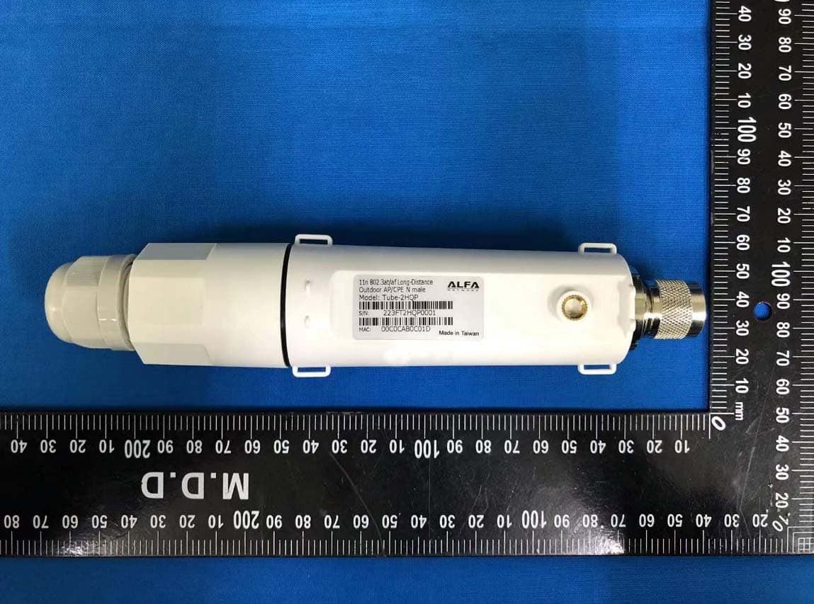
2AB8795312
Jun 19, 2022Outdoor AP/CPE
Equipment Class
DTS - Digital Transmission System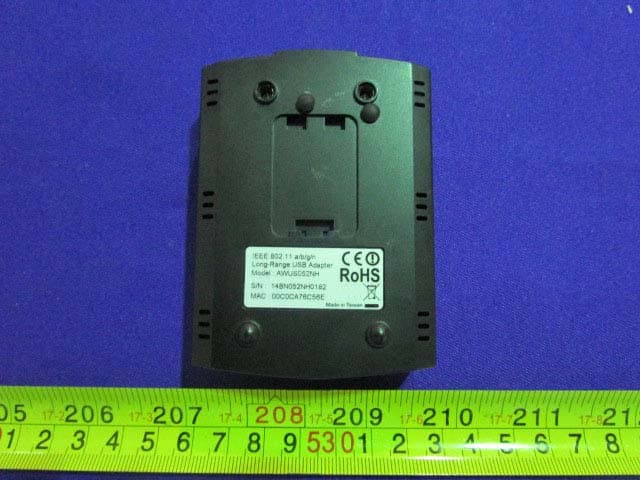
2AB87572
Jun 10, 2015802.11a/b/g/n Long-Range USB Adapter Dual-Band 2.4/5 GHz
Equipment Class
NII - Unlicensed National Information Infrastructure TX