2ABBXCM9301SDT2014Bluetooth 4.0 Module
C-MAX Asia limited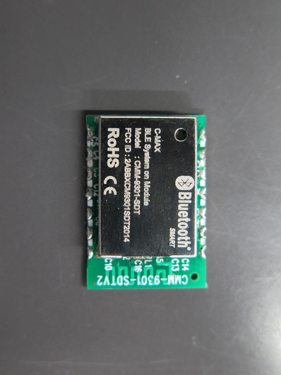
Click to zoom
Application Details
- Equipment Class
- DXX - Part 15 Low Power Communication Device Transmitter
- Date of Grant
- Mar 12, 2015
- Application Purpose
- Original Equipment
- Date of Application
- Mar 12, 2015
- Equipment Note
- Bluetooth 4.0 Module
- Frequency Range
- 2402.00000000 - 2480.00000000
- Company
- C-MAX Asia limited
- Country
- Hong Kong
Documents & Files
Document Text
Text extracted from the exhibit documents filed with the FCC. Open a document above to read the original.
Users Manual
CMM-9301-SDT Bluetooth Low Energy Serial Data Bridge Module This module is limited to OEM installation ONLY SPEC No. CMM-9301-SDT BLE Bridge module Revision 2.0 State 2015-03-04 C-MAX printed 2015-03-04 Version English Page 1 of 16 C-MAX 1.0 Description The CMM-9301-SDT module is a Bluetooth 4.0 Single Mode (Bluetooth Low Energy) module for implementing Bluetooth functionality into various electronic devices. Standalone as a Bluetooth Low Energy End Product, it is embedded with a proprietary data exchange profile allowing the bridging of data from an external host by means of UART link via Bluetooth 4.0 protocol to a Bluetooth 4.0 Dual Mode device. Inclusive of dedicated hardware for the Physical and Link Layer implementation of Bluetooth Smart from EM Microelectronics and a high performance interface MCU, this SDT module is optimized for embedded applications such as health monitoring, sports devices, human sensoring devices, home appliances etc. Without any additional study of the Bluetooth protocol, customers are able to develop and test their own applications. 1.1 Features o Bluetooth Low Energy (BLE) (Single Mode) full corestack embedded module in slave mode o Enables application with Bluetooth connectivity with no Bluetooth knowledge required whatsoever o Embedded with BT4.0 GATT profile and Device Information Service o 1Mbps on-air data rate o Programmable BLE parameters such as: Device Information, connection interval and more... o UART interface with external host via AT command set o Dimension: 15.5 x 22.5 x 3.2 mm o No tuning necessary o Operational Temperature Range -20 / +60°C o Tape and Reel packaged ready for SMT assembly 1.2 Pin Assignments and Dimensions Top View Detailed Dimensions All dimensions are in mm. Connection pin pitch = 2.54 mm +/- 0.1mm Module Thickness = 3.2mm max. CMM-9301-SDT Bluetooth Low Energy Serial Data Bridge Module SPEC No. CMM-9301-SDT BLE Bridge module Revision 2.0 State 2015-03-04 C-MAX printed 2015-03-04 Version English Page 2 of 16 C-MAX Pin Number Pin Name Input to / Output from Module Pin Description 1 RXD I RXD pin of UART communication with Host 2 Reserved I/O Reserved pin for future use 3 Reserved I/O Reserved pin for future use 4 Reserved I/O Reserved pin for future use 5 Reserved I/O Reserved pin for future use 6 GND GND Ground connection for module 7 TXD O TXD pin of UART communication with Host 8 UART_EN I Connect to VCC for UART serial data transfer mode 9 SLEEP I Module wake up pin to wake module from low power sleep mode (Wake-up = LO, Sleep = HI) . In Sleep mode UART interface will be disabled. 10 VDD VDD 2.3 ~ 3.6 V voltage supply pin to module 11 IRQ O Interrupt Request Pin to signal host when data received in buffer and ready to poll 12 RST I Reset (Active LO) 13 LINK O Module Link Indication signal (Bluetooth Disconnected = LO; Bluetooth Connected = HI) 14 RESERVED I/O Reserved pin for future use 1.3 Recommended PCB layout and foot print Recommended module contact pads footprint CMM-9301-SDT Bluetooth Low Energy Serial Data Bridge Module SPEC No. CMM-9301-SDT BLE Bridge module Revision 2.0 State 2015-03-04 C-MAX printed 2015-03-04 Version English Page 3 of 16 C-MAX Recommended Clearance Recommended Keepout area around Module and Ground Plane Area under Module 1.4 Module Block Diagram CMM-9301-SDT Bluetooth Low Energy Serial Data Bridge Module SPEC No. CMM-9301-SDT BLE Bridge module Revision 2.0 State 2015-03-04 C-MAX printed 2015-03-04 Version English Page 4 of 16 C-MAX 1.5 Functional Modes In general, the module has three functional modes of operation: A. Sleep Mode: A HI state on the SLEEP pin will put the module into this mode, where the processor in the module is in low power sleep mode. In this mode, the module cannot communicate with the Host via UART communication. However, Bluetooth can be kept on and connected in this mode to listen for any incoming data packets. The module will only be waken by a LO enable signal on the SLEEP pin . B. On Mode: A LO state on the SLEEP pin will put the module into this mode. In this mode, the processor in the module is awake and ready to communicate with the Host via UART communication. UART communication is possible for all AT command operations. Once SLEEP pin is set back to HI, the module will enter into Sleep Mode. C. Test Mode: This mode is used for RF testing purposes only. By sending an AT command from HOST to module (making sure that the SLEEP pin is set to LO first), the module will start RF Test mode. By sending different test data to the SDT, the HOST can control the module to transmit on different frequencies, in two different transmission modes : unmodulated carrier or modulated carrier with test data pattern alternating 1s and 0s. 2. HOST Interface specification 2.1 Overview UART interface is used for data transfer between host and SDT module. The HOST system can send command/data or receive event information/data via UART interface. 2.2 Connection with HOST systems Connection with HOST system consist of the UART interface and 3 control pins. The below is a reference diagram for the connection of the CMM-9301-SDTV2 module with an external host processor: The 3 control pins have the following functionality. CMM-9301-SDT Bluetooth Low Energy Serial Data Bridge Module SPEC No. CMM-9301-SDT BLE Bridge module Revision 2.0 State 2015-03-04 C-MAX printed 2015-03-04 Version English Page 5 of 16 C-MAX LINK: This pin indicates to HOST system the Bluetooth connectivity state of the SDT module. LINK signal will be asserted to LOW at power up and in the event of Bluetooth disconnected. During Bluetooth connected phase, LINK signal will be stay HIGH. SLEEP: Control signal by HOST to wake module and start UART communication. It has to be asserted Low before start serial communication. Asserting this pin back to High will put module into low power sleep mode. Note that this pin does not control the Bluetooth connectivity. Bluetooth connectivity has to be controlled via AT commands. IRQ: I…
Text truncated - open the document above for the full version.
Cover Letter(s)
皺皺撞撞 16 January, 2015 To whom it may concern, We the undersigned, hereby authorize CMA Industrial Development Foundation Limited (Andrew Wong) to act on our behalf in all manners relating to application for equipment authorization , including signing of all documents relating to those matters. Any and all acts carried out by authorize CMA Industrial Development Foundation Limited on our behalf shall have the same affect as acts of our own. Sincerely , AJd一 切ichaelChiu General Manager C-MAX Asia Limited
Cover Letter(s)
器輯窩窩 16 January, 2015 Equipment Authorization Division Office id Engineering and Technology Federal Communications Commission 7435 Oakland Mills Road Columbia , MD 21046 Dear Sirs: C-MAX Asia Limited requests acceptance of the labeling proposal described below for CMM-9301-SDT bearing FCC identifier 2ABBXCM901SDT2014. The subject 2 .4GHz Transceiver module CMM-9301-SDT model as shown in figure 1, authorized under FCC Part 15 Class C figure 1 聽鐵窩窩 It is because the surface of the device does not enough to indicate the FCC statement. For this reason , C-MAX ASIA LlMITEO proposes those statements is showing on the user manual and the device is carrying the FCC 10 number only. The figure2 is showing the FCC 10 location. figure 2 Sincerely , C-MAX Asia Limited General Manager
Cover Letter(s)
輯滋滋 POWER OF ATTORNEY 16 January, 2015 Federal Communications Commission Authorization and Evaluation Division 7435 Oakland Mills Road Columbia , MD 21046 To Whom It May Concern, FCC ID :2ABBXCM9301SDT2014 We , the undersigned, hereby authorize CMA Industrial Development Foundations Limited (Andrew Wong) on our behalf, to apply to the Federal Communications Commission on our equipment. Any and all acts carried out by CMA Industrial Development Foundation Limited (Andrew Wong) on our behalf shall have the same effect as acts of our own. This authorization expires one year from original date. This is to advise that we are in full compliance with the Anti-Drug Abuse Act. We C-MAX Asia Limited, are not subject to a denial of federal benefits pursuant to Section 5301 of the Anti-Drug Act of 1988, 21 USC853a, and no pa吋Yto the application is subject to a denial of federal benefits pursuant to that section. Sincerely , ;戶fì General Manager C-MAX Asia Limited
External Photos
External Photo
ID Label/Location Info
Label Sample
Internal Photos
Internal Photo
Test Report
TEST REPORT Report No. : AT0011900(0) Date : 03 Mar 2015 For and on behalf of CMA Industrial Development Foundation Limited Authorized Signature : Page 1 of 27 Mr. WONG Lap-pong, Andrew Manager Electrical Division FCC ID: 2ABBXCM9301SDT2014 Application No. : LT005971(0) Applicant : C-MAX Asia Limited Room 117, 1/F, Liven House, 61-63 King Yip Street, Kwun Tong, Hong Kong Sample Description : One(1) item of submitted sample stated to be Bluetooth 4.0 Module of Model No. CMM-9301-SDT Sample registration No. : RT009363-001 Radio Frequency : 2408MHz – 2480 MHz Transceiver Rating : 2 x 1.5V AA size batteries No. of submitted sample : Two (2) piece (s) Date Received : 04 Feb 2015 Test Period : 05 Feb 2015 to 25 Feb 2015. Test Requested : FCC Part 15 Certificate (15.249) Test Method : 47 CFR Part 15 (10-1-12 Edition), ANSI C63. 4 – 2009 Test Engineer : Mr. LEUNG Shu-kan, Ken Test Result : See attached sheet(s) from page 2 to 27. Conclusion : The submitted sample was found to comply with requirement of FCC Part 15 Subpart B and C. TEST REPORT Report No. : AT0011900(0) Date : 03 Mar 2015 Page 2 of 27 FCC ID: 2ABBXCM9301SDT2014 Table of Contents 1 General Information ................................................................................................................................... 3 1.1 General Description ............................................................................................................................ 3 1.2 Location of the test site ....................................................................................................................... 4 1.3 List of measuring equipment............................................................................................................... 5 1.4 Measurement Uncertainty ................................................................................................................... 6 2 Description of the radiated emission test ................................................................................................... 7 2.1 Test Procedure .................................................................................................................................... 7 2.2 Test Result .......................................................................................................................................... 8 2.3 Radiated Emission Measurement Data ............................................................................................... 9 3 Description of the Line-conducted Test ................................................................................................... 13 3.1 Test Procedure .................................................................................................................................. 13 3.2 Test Result ........................................................................................................................................ 13 3.3 Graph and Table of Conducted Emission Measurement Data .......................................................... 13 4 Photograph ............................................................................................................................................... 14 4.1 Photographs of the Test Setup for Radiated Emission and Conducted Emission ............................. 14 4.2 Photographs of the External and Internal Configurations of the EUT .............................................. 14 5 Supplementary document ......................................................................................................................... 15 5.1 Bandwidth ......................................................................................................................................... 15 5.2 Duty cycle ......................................................................................................................................... 15 5.3 Transmission time ............................................................................................................................. 15 5.4 Power Spectral Density ..................................................................................................................... 15 5.5 Average on time ................................................................................................................................ 15 6 Appendices ............................................................................................................................................... 16 TEST REPORT Report No. : AT0011900(0) Date : 03 Mar 2015 Page 3 of 27 FCC ID: 2ABBXCM9301SDT2014 1 General Information 1.1 General Description The equipment under test (EUT) is a transceiver module for 2.4GHz wireless device. The EUT is power by 3V dc. The EUT contain shielding, internal grounding and built in with a folded-dipole PCB antenna. The EUT can mount on other device through surface. The brief circuit description is listed as follows: - X2 and its associated circuit act as oscillator - L1, L2, C15, C16 and its associated circuit act as antenna matching - U1, U2 and its associated circuit act as controller TEST REPORT Report No. : AT0011900(0) Date : 03 Mar 2015 Page 4 of 27 FCC ID: 2ABBXCM9301SDT2014 1.2 Location of the test site FCC Registered Test Site Number: 552221 Radiated emissions measurements are investigated and taken pursuant to the procedures of ANSI C63.4 – 2009. A Semi-Anechoic Chamber Testing Site is set up for investigation and located at: Ground Floor, Yan Hing Centre, 9 – 13 Wong Chuk Yeung Street, Fo Tan, Shatin, New Territories, Hong Kong. Conducted emissions measurements are investigated and also taken pursuant to the procedures of ANSI C63.4 – 2009. A shielded room is located at : Ground Floor, Yan Hing Centre, 9 – 13 Wong Chuk Yeung Street, Fo Tan, Shatin, New Territories, Hong Kong. TEST REPORT Report No. : AT0011900(0) Date : 03 Mar 2015 Page 5 of 27 FCC ID: 2ABBXCM9301SDT2014 1.3 List of measuring equipme…
Text truncated - open the document above for the full version.
Test Report
TEST REPORT Report No. : AT0011900(0) Date : 03 Mar 2015 Tested by: Reviewed by: Mr. LEUNG Shu-kan, Ken Mr. WONG Lap-pong, Andrew Page 24 of 27 FCC ID: 2ABBXCM9301SDT2014 A5. Band Edge Lower edge (Peak measurement) Lower edge (Average measurement) TEST REPORT Report No. : AT0011900(0) Date : 03 Mar 2015 Tested by: Reviewed by: Mr. LEUNG Shu-kan, Ken Mr. WONG Lap-pong, Andrew Page 25 of 27 FCC ID: 2ABBXCM9301SDT2014 A5. Band Edge Higher edge (Peak measurement) Higher edge (Average measurement)
Test Report
TEST REPORT Report No. : AT0011900(0) Date : 03 Mar 2015 Tested by: Reviewed by: Mr. LEUNG Shu-kan, Ken Mr. WONG Lap-pong, Andrew Page 26 of 27 FCC ID: 2ABBXCM9301SDT2014 A6. 20dB Bandwidth Plot Bandwidth 1 (2402MHz) Bandwidth 2 (2442MHz) TEST REPORT Report No. : AT0011900(0) Date : 03 Mar 2015 Tested by: Reviewed by: Mr. LEUNG Shu-kan, Ken Mr. WONG Lap-pong, Andrew Page 27 of 27 FCC ID: 2ABBXCM9301SDT2014 A6. 20dB Bandwidth Plot Bandwidth 3 (2480MHz) ***** End of Report *****
Test Setup Photos
Test Setup Photo Front view (30MHz – 1GHz) Rear view (30Mz – 1GHz) Front view (9kHz – 30MHz) Rear view (9kHz – 30MHz) Front view (1GHz – 25GHz) Rear view (1GHz – 25GHz) EUT with control board (top view) EUT with control board (bottom view)
Contact Information
Applicant
Michael Chiu(General Manager)
Test Firm
CMA Industrial Development Foundation LimitedJoey Kwok
[email protected]+852 2690 8255
Technical Specifications
| # | Rule Parts | Frequency Range | Power Output |
|---|---|---|---|
| 1 | 15C | 2.40 GHz - 2.48 GHz | - |
Other Applications from C-MAX Asia limited
2ABBXCMP9304BC0819
Mar 25, 2020Beacon Broadcast Device with Bluetooth
Equipment Class
DTS - Digital Transmission System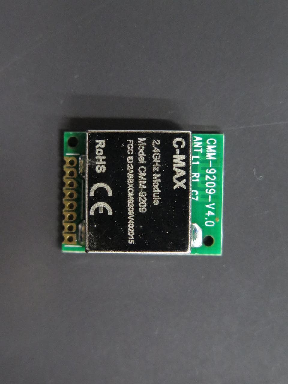
2ABBXCM9209V402015
Feb 24, 20152.4GHz Module
Equipment Class
DXX - Part 15 Low Power Communication Device Transmitter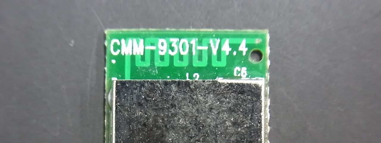
2ABBXCM9301V442014
Aug 21, 2014Bluetooth Module
Equipment Class
DXX - Part 15 Low Power Communication Device Transmitter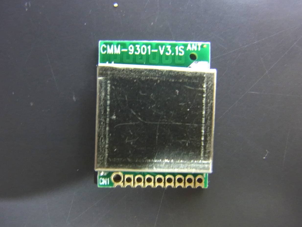
2ABBXCM9301V312013
Jan 02, 2014BLUETOOTH 4.0 SINGLE MODE HCI MODULE
Equipment Class
DXX - Part 15 Low Power Communication Device Transmitter