2ABBXCMP9304BC0819Beacon Broadcast Device with Bluetooth
C-MAX Asia limited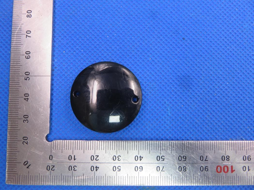
Click to zoom
Application Details
- Equipment Class
- DTS - Digital Transmission System
- Date of Grant
- Mar 25, 2020
- Application Purpose
- Original Equipment
- Date of Application
- Mar 25, 2020
- Equipment Note
- Beacon Broadcast Device with Bluetooth
- Frequency Range
- 2402.00000000 - 2480.00000000
- Company
- C-MAX Asia limited
- Country
- Hong Kong
Documents & Files
Document Text
Text extracted from the exhibit documents filed with the FCC. Open a document above to read the original.
Users Manual
C-MAX Beacon BC08 Datasheet SPEC No. C-MAX Beacon BC08 DataSheet Revision 1.3 State 2019-11-28 Printed 2020-03-26 Version English Page 1 of 8 C-MAX Beacon Broadcast Device CMP-9304BC08 C-MAX Beacon BC08 Datasheet SPEC No. C-MAX Beacon BC08 DataSheet Revision 1.3 State 2019-12-17 Printed 2020-03-26 Version English Page 2 of 8 C-MAX 1 Description The CMP-9304BC08 is a Bluetooth Low-Energy proximity beacon suitable for mass deployment by system integrators. The device advertises ID data that is compatible with common beacon standards (UUID, Major ID, and Minor ID). An supervisor mobile APP is also available for over-the-air beacon settings to configure parameters such as UUID, Major ID, Minor ID, advertising intervals and measured power at 1 meter. 1.1 Features ID packet format includes: UUID, Major ID, and Minor ID Output power information Beacon interval programmable via mobile APP for flexible power consumption management. Default interval is 1 second. UUID programmable via mobile APP. Major and Minor IDs programmable via mobile APP to suit user’s self-customization. Measured power at 1 meter programmable via mobile APP to configure the reference RSSI at 1 meter distance 1.2 Dimensions – Beacon Main Unit (designations in mm) 1.3 Bluetooth Address Bluetooth Address: 0C:F3:EE:XX:XX:XX 2. Operation Manual C-MAX Beacon BC08 Datasheet SPEC No. C-MAX Beacon BC08 DataSheet Revision 1.3 State 2019-12-17 Printed 2020-03-26 Version English Page 3 of 8 C-MAX 2.1 Operational Flow 2.2 Initial Activation Upon first use or after new ID is programmed into the beacon device, the beacon will be in standby activation mode. A Supervisor mobile APP has to be used to activate the beacon into normal active broadcast mode. Upon launching the APP, selecting USER mode, input the serial number of the beacon to be activated and then a simple click on “Activate” will activate the beacon which should be placed next to the Apple mobile device. If after battery is replaced, the device will remain in receive mode for 1 minute waiting for new ID to be programmed, if no new ID is programmed, the device will go into normal beacon mode, without the need for activation. APP configurable device settings Power On (battery inserted) Receive Mode (for ID programming) Broadcast Mode (Normal Beacon Mode) Programmed new ID via APP Test Broadcast Mode (for ID verification) Sleep Mode (wait for activation) User Activation via mobile APP within 1 min after 1 min after 1 min timeout C-MAX Beacon BC08 Datasheet SPEC No. C-MAX Beacon BC08 DataSheet Revision 1.3 State 2019-12-17 Printed 2020-03-26 Version English Page 4 of 8 C-MAX 2.3 iBeacon Broadcast The normal Beacon Advertisement packet will be broadcasted every 1 second or at an interval set by the user between 100 milliseconds and 10 seconds. The broadcasting packet is according to the following standard Apple iBeacon format: The packet consists of : UUID (16 bytes or 32 hexadecimal characters). By default it is set to C-MAX’s UUID: E2C56DB5-DFFB-48D2-B060-D0F5A71096E0. Major ID (2 bytes or 4 hexadecimal characters). By default, it is set to a value of 10000, unless C-MAX has a list of specific major IDs to be pre-programmed for the customer upon product shipment. Minor ID (2 bytes or 4 hexadecimal characters). By default, it is set to a value of 10, unless C-MAX has a list of specific minor IDs to be pre-programmed for the customer upon product shipment. RSSI as at 1m. As adjusted by measured power level at 1 metre distance. This parameter can be used by a mobile APP for distance computation. E2C56DB5-DFFB-48D2-B060-D0F5A71096E0 C-MAX Beacon BC08 Datasheet SPEC No. C-MAX Beacon BC08 DataSheet Revision 1.3 State 2019-12-17 Printed 2020-03-26 Version English Page 5 of 8 C-MAX 2.4 Battery Level Broadcast An additional supplement advertisement packet will be broadcasted every 5 mins by default or at an interval specified by the user within the range of 1 seconds and 3600 seconds. This allows the mobile APP to check for the battery voltage and alert for battery low conditions. 2.5 Beacon Settings Customization If the Beacon is configured as “ENABLE PROGRAMMING”, the user can customise his own beacon parameters including the following: - Programmable UUID o 16 bytes, each byte ranging from 0x00 to 0xFF o Default set = E2C56DB5-DFFB-48D2-B060-D0F5A71096E0 - Programmable Major ID o Range from 0x0001 to 0xFFFF o Default set = 10000 - Programmable Minor ID o Range from 0x0001 to 0xFFFF o Default set = 10 - Programmable Advertising Interval o Input range from 600 milliseconds to 10000 milliseconds - Battery Level Broadcast Interval o Input range from 1 second to 3600 seconds o Default set = 300 seconds (that is, 5 minutes) - Programmable Measured Power at 1 meter o 2’s complement of the calibrated TxPower, from 0x00 to 0xFF o Default set = 0xC5 = -59dBm 3. Electrical Characteristics Specification Min Typ Max Units Condition Operating Voltage 2.6 3.0 3.3 Lithium Coin cell CR2032 battery, 25 °C , 50% humidity Battery Lifetime (Before Activation) 50 months CR2032 battery with 220 mAh @ 80% capacity Battery Lifetime (After Activation) 18 months CR2032 battery with 220 mAh @ 80% capacity, Beacon C-MAX Beacon BC08 Datasheet SPEC No. C-MAX Beacon BC08 DataSheet Revision 1.3 State 2019-12-17 Printed 2020-03-26 Version English Page 6 of 8 C-MAX (1 sec broadcast interval) broadcast interval = 1 sec, Output power = +0.4 dBm, 25 °C , 50% humidity Beacon Interval 1 sec Default Average Current (Before Activation) 5 uA Scanning for activation Average Current (After Activation) 14 uA 1 seconds iBeacon broadcast interval + 20 seconds Battery Level Advertisement Interval Range 30 m At default broadcast output power and interval, 25 °C , 50% humidity Operating Temperature -10 +60 °C 3V operating voltage 4. Ordering Information Part Number Description Colours Available Image CMP-9304BC08-A Beacon Main Unit Black 5. FCC Warning Statement FEDERAL COMMUNICATIONS COMMISSION INTERFERENCE STATE…
Text truncated - open the document above for the full version.
Cover Letter(s)
Dec. 06, 2019 Federal Communication Commission Authorization and Evaluation Division FCC ID: 2ABBXCMP9304BC0819 Re: Confidentiality Request Pursuant to Sections 0.457 and 0.459 of the Commission’s Rules, the applicant hereby requests confidential treatment of information applied this application as outlined below: 1: Block Diagram 2: Schematics 3: Operational Description The above materials contain trade secrets and proprietary information not customarily released to the public. The public disclosure of these matters might be harmful to the applicant and provide unjustified benefits to its competitors. The Applicant understands that pursuant to Rules 0.457, disclosure of this Application and all accompanying documentation will not be made before the date of the Grant for this application. Sincerely, C-MAX Asia limited Contact person: Michael Chiu
External Photos
External Photos TOP VIEW OF EUT BOTTOM VIEW OF EUT FRONT VIEW OF EUT BACK VIEW OF EUT LEFT VIEW OF EUT RIGHT VIEW OF EUT
ID Label/Location Info
FCC ID Label Location FCC ID: 2ABBXCMP9304BC0819
Internal Photos
Internal Photos OPEN VIEW OF EUT-1 OPEN VIEW OF EUT-2 INTERNAL VIEW OF EUT-1 INTERNAL VIEW OF EUT-2 INTERNAL VIEW OF EUT-3 INTERNAL VIEW OF EUT-4 BT Antenna
Test Report
Page 1 of 45 FCC Test Report Report No.: AGC06953190801FE02 FCC ID : 2ABBXCMP9304BC0819 APPLICATION PURPOSE : Original Equipment PRODUCT DESIGNATION : Beacon Broadcast Device BRAND NAME : C-MAX MODEL NAME : CMP-9304BC08 APPLICANT : C-MAX ASIA LIMITED DATE OF ISSUE : Nov. 01, 2019 STANDARD(S) : FCC Part 15.247 REPORT VERSION : V1.0 Attestation of Global Compliance (Shenzhen) Co., Ltd CAUTION: This report shall not be reproduced except in full without the written permission of the test laboratory and shall not be quoted out of context. Report No.: AGC06953190801FE02 Page 2 of 45 REPORT REVISE RECORD Report Version Revise Time Issued Date Valid Version Notes V1.0 / Nov. 01, 2019 Valid Initial Release Report No.: AGC06953190801FE02 Page 3 of 45 TABLE OF CONTENTS 1. VERIFICATION OF COMPLIANCE ............................................................................................................... 5 2. GENERAL INFORMATION ............................................................................................................................ 6 2.1. PRODUCT DESCRIPTION .................................................................................................................... 6 2.2. TABLE OF CARRIER FREQUENCYS ................................................................................................... 6 2.3. RELATED SUBMITTAL(S)/GRANT(S) ................................................................................................... 7 2.4. TEST METHODOLOGY ......................................................................................................................... 7 2.5. SPECIAL ACCESSORIES ..................................................................................................................... 7 2.6. EQUIPMENT MODIFICATIONS ............................................................................................................. 7 3. MEASUREMENT UNCERTAINTY ................................................................................................................. 8 4. DESCRIPTION OF TEST MODES ................................................................................................................. 9 5. SYSTEM TEST CONFIGURATION ............................................................................................................. 10 5.1. CONFIGURATION OF TESTED SYSTEM ........................................................................................... 10 5.2. EQUIPMENT USED IN TESTED SYSTEM .......................................................................................... 10 5.3. SUMMARY OF TEST RESULTS .......................................................................................................... 10 6. TEST FACILITY ............................................................................................................................................ 11 7. PEAK OUTPUT POWER ............................................................................................................................. 12 7.1. MEASUREMENT PROCEDURE .......................................................................................................... 12 7.2. TEST SET-UP (BLOCK DIAGRAM OF CONFIGURATION) ................................................................. 12 7.3. LIMITS AND MEASUREMENT RESULT .............................................................................................. 13 8. 6 DB BANDWIDTH ...................................................................................................................................... 15 8.1. MEASUREMENT PROCEDURE .......................................................................................................... 15 8.2. TEST SET-UP (BLOCK DIAGRAM OF CONFIGURATION) ................................................................. 15 8.3. LIMITS AND MEASUREMENT RESULTS ........................................................................................... 15 9. CONDUCTED SPURIOUS EMISSION ........................................................................................................ 17 9.1. MEASUREMENT PROCEDURE .......................................................................................................... 17 9.2. TEST SET-UP (BLOCK DIAGRAM OF CONFIGURATION) ................................................................. 17 9.3. MEASUREMENT EQUIPMENT USED ................................................................................................ 17 9.4. LIMITS AND MEASUREMENT RESULT .............................................................................................. 17 10. MAXIMUM CONDUCTED OUTPUT POWER SPECTRAL DENSITY ....................................................... 22 10.1. MEASUREMENT PROCEDURE ........................................................................................................ 22 10.2. TEST SET-UP (BLOCK DIAGRAM OF CONFIGURATION) ............................................................... 22 10.3. MEASUREMENT EQUIPMENT USED .............................................................................................. 22 10.4. LIMITS AND MEASUREMENT RESULT ............................................................................................ 22 11. RADIATED EMISSION ............................................................................................................................... 24 11.1. MEASUREMENT PROCEDURE ........................................................................................................ 24 11.2. TEST SETUP ..................................................................................................................................... 25 11.3. LIMITS AND MEASUREMENT RESULT ............................................................................................ 26 11.4. TEST RESULT ................................................................................................................................... 26…
Text truncated - open the document above for the full version.
Test Setup Photos
Test Setup Photos RADIATED EMISSION TEST SETUP BELOW 1GHZ RADIATED EMISSION TEST SETUP ABOVE 1GHZ CONDUCTED TEST SETUP
Contact Information
Applicant
Michael Chiu(General Manager)
Test Firm
Attestation of Global Compliance (Shenzhen) Co., LDoris Li
[email protected]+86-755-25234088
Technical Specifications
| # | Rule Parts | Frequency Range | Power Output |
|---|---|---|---|
| 1 | 15C | 2.40 GHz - 2.48 GHz | 2.00 mW |
Other Applications from C-MAX Asia limited
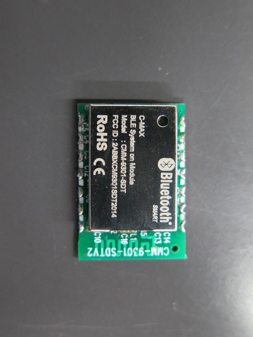
2ABBXCM9301SDT2014
Mar 12, 2015Bluetooth 4.0 Module
Equipment Class
DXX - Part 15 Low Power Communication Device Transmitter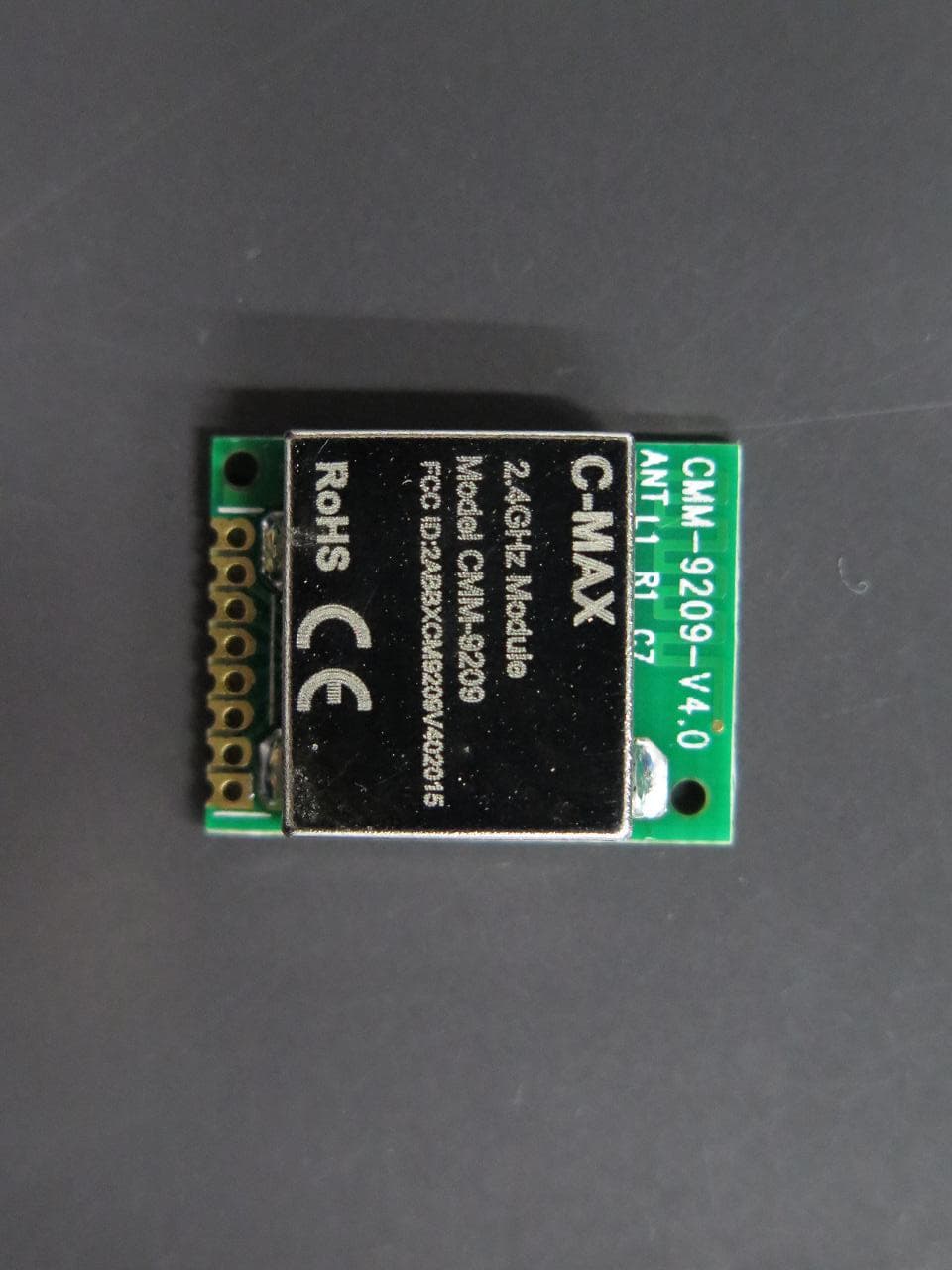
2ABBXCM9209V402015
Feb 24, 20152.4GHz Module
Equipment Class
DXX - Part 15 Low Power Communication Device Transmitter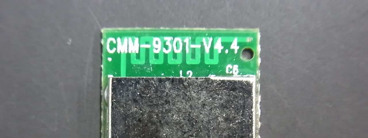
2ABBXCM9301V442014
Aug 21, 2014Bluetooth Module
Equipment Class
DXX - Part 15 Low Power Communication Device Transmitter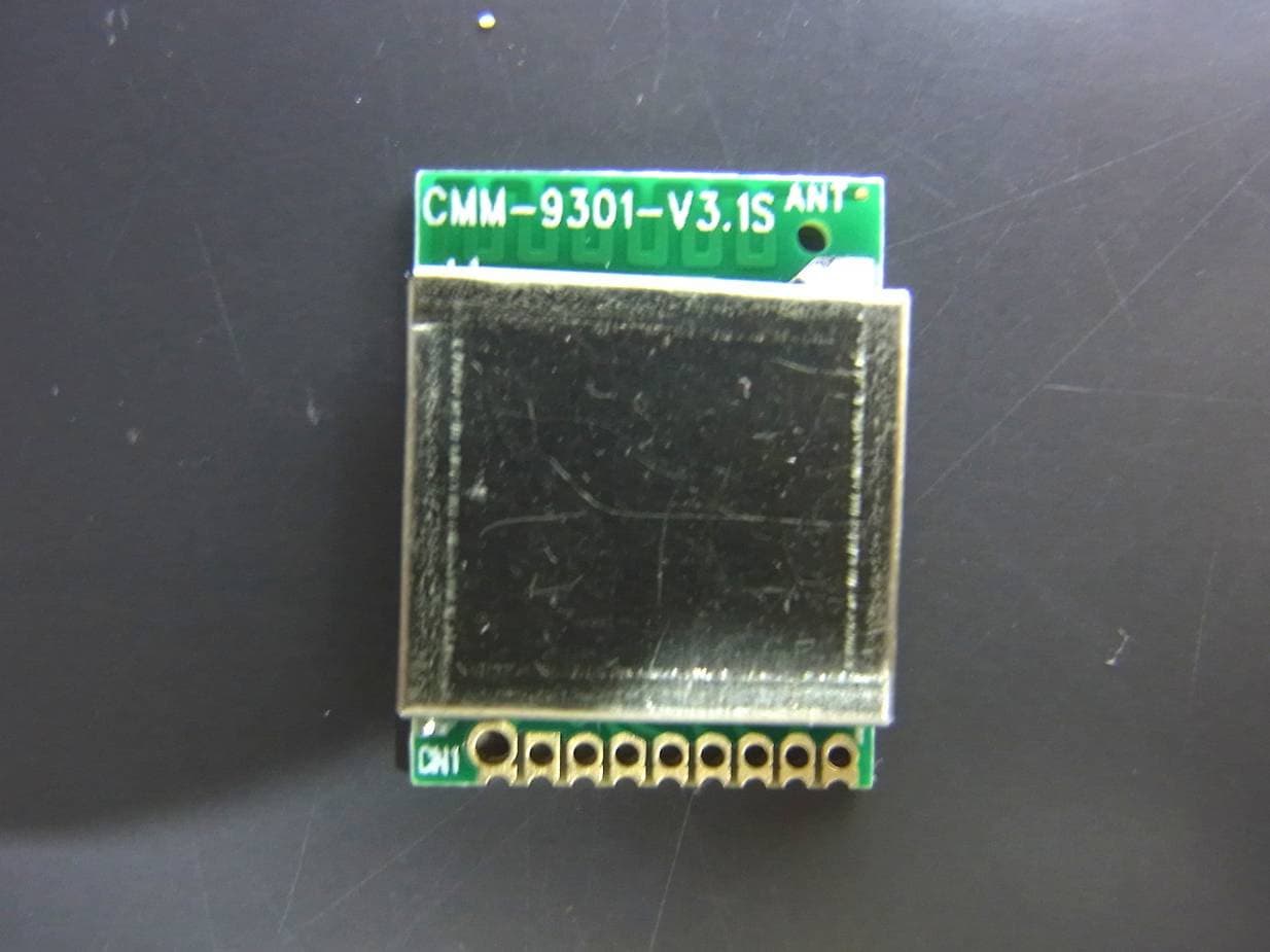
2ABBXCM9301V312013
Jan 02, 2014BLUETOOTH 4.0 SINGLE MODE HCI MODULE
Equipment Class
DXX - Part 15 Low Power Communication Device Transmitter