2ABES-PILOTX01PilotX Tablet
Pathway Innovations and Technologies, Inc.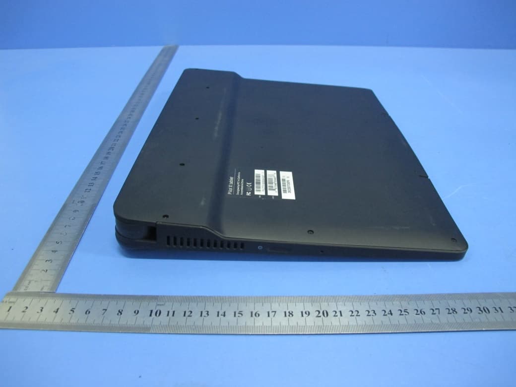
Click to zoom
Application Details
- Equipment Class
- DTS - Digital Transmission System
- Date of Grant
- Jan 06, 2020
- Application Purpose
- Original Equipment
- Date of Application
- Jan 06, 2020
- Equipment Note
- PilotX Tablet
- Frequency Range
- 2412.00000000 - 2462.00000000
- Country
- United States
Documents & Files
Document Text
Text extracted from the exhibit documents filed with the FCC. Open a document above to read the original.
Users Manual
Pilot X Digital Teaching Station User’s Manual © Copyright HoverCam® © Copyright HoverCam® 2019 In a Hurry? Watch the Pilot X Quick Start Video Go to www.hovercam.com/support/training-videos or Scan this QR code with your phone’s camera: Pilot X Quick Start Video Table of Contents2 © Copyright HoverCam® 2019 Welcome 3 Main FeaturesWhat’s In the Box Diagrams 4 Assembling the Podium 6 Adjusting the Podium 8 Charging 9 Charging the PodiumCharging the Tablet Operating the Tablet 11 TouchscreenActive Stylus Internal PCWindows 10 ImagingThumb Strap Pop-Out KeyboardThird Party Accessories Document Camera 17 Deploying and PositioningSoftware HoverCast Wireless HDMI 19 AboutSetting Up PositioningTroubleshooting Wired HDMI 26 Audio 27 Audio-InAudio-Out Specifications 30 Service and Support 31 Warranty 32 Safety Warnings 34 Notices 37 Legal 38 3 Congratulations! With Pilot X, you’ve taken a major step in revolutionizing your classroom. Designed by educational technology professionals in California, the Pilot X brings every essential educational technology component to your fingertips: a tablet computer, document camera, and wireless podium. Say goodbye to messy cables, because with Pilot X, you can wirelessly control your classroom display from anywhere in the room. • Microsoft ® Windows ® 10 tablet computer (license not included), powered by Intel ® • 13.3” Multitouch display, with #2 pencil stylus capability • Wireless, lag-free HD casting via HoverCast • Wirelessly control and cast bi-directional annotations from USB-touch enabled displays • Fold-out 4K document camera • Mobile podium charging station for up to 6 hours of wireless use • Tablet dock with built-in keyboard • Lockable tablet bay for overnight security and charging • Design, present lessons and manage student success with included ClassFusion software Main Features What’s in the Box Welcome 3 Podium Surface Tablet Computer Podium Pedestal Podium Wheel Base HoverCast Receiver Magnetic Document Bumpers Active Stylus with USB charging cable Tablet Thumb Strap with 2x 10mm screws Podium Power Adapter - 10ft. Tablet Power Adapter - 10ft. Hardware and Assembly Tools HDMI Cable - 5ft. Mini-HDMI to HDMI 2.0 Cable - 5ft. HoverCast Power Adapter - 10ft. Type B USB 2.0 Cable - 5ft. Type A USB 2.0 Cable - 5ft. x12 © Copyright HoverCam® 2019 13 Podium Diagram 4 1 23 4 8 9 10 12 11 65 7 1 2 3 4 5 7 8 9 Magnetic Tablet Dock Pop-Out Keyboard Tablet Bay Charging Actuator x2 Magnetic Anti-Slip Bumpers Tablet Storage Bay Tablet Bay Combination Lock Charging System On/Off Button Magnetic Power Port Tilt Adjustment Dial 10 6 11 12 Podium Audio Line In/Out 4x Lockable Wheels Height Adjustment Foot Pedal © Copyright HoverCam® 2019 13 Tablet Diagram 5 18 19 20 21 22Magnetic Docking Connector USB 3.0 Type A (2x) USB 3.0 Type C Mini HDMI-Out Audio Line In/Out Connectivity 13 14 15 16 17 12AutoFocus On Image Flip Zoom-Out Camera Reset AutoFocus Lock Freeze Camera Controls 11Zoom-In 8 9 10 7 3 2 5 18 19 20 21 RESET 14151617 111213 4 22 1 1 2 3 4 5 7 8 9 Fold-Out Document Camera HoverCast Wireless Antenna HoverCast Antenna On/Off 1 Watt Tablet Speaker (2x) Tablet Charging Indicator Kensington Lock 13.3” Multi-Touch Display Fingerprint Scanner / Menu Tablet Sleep/Wake Button Tablet Features 10 6 HoverCast Reset 6 © Copyright HoverCam® 2019 8x 4mm Bolts 4mm Hex Driver Optional Thread-Locking Compound (Not Included) Notice: Two people are required to safely assemble Pilot X 13 Assembling the Podium 6 Step 1 Step 2 Step 3 Carefully unpack the Pilot X Podium Surface, Podium Pedestal, Podium Wheel Base, Hardware and Assembly Tools. Stage the components on the included foam packaging, or use a padded surface. Podium SurfacePodium Pedestal Podium Wheel Base Hardware and Assembly Tools Place the Podium Surface upside down on a padded surface, making sure the Tilt Adjustment Dial is in the locked position by rotating it clockwise to the furthest position. Carefully place the Podium Pedestal onto the Podium Surface, making sure the 8x 4mm bolt holes line up properly. Next use the included hex driver to secure 8x 4mm Bolts as pictured below, being careful not to strip the threads. Optionally, a thread-locking compound may be used to prevent loosening of the bolts over time (not included). Loctite® Threadlocker Blue 242® is a recommended compound. x12 © Copyright HoverCam® 2019 13 Assembling the Podium 7 Step 4 Step 5 Insert the Podium Wheel Base onto the Podium Pedestal, making sure the Height Adjustment Foot Pedal is on the same side as the Pop-Out Keyboard. Use the included Hex Driver to secure 4x 4mm bolts as pictured below, being careful not to strip the threads. Optionally, a thread-locking compound may be used to prevent loosening of the bolts over time (not included). Loctite® Threadlocker Blue 242® is a recommended compound. Ensure that the 4x Podium Wheels’ levers are in the locked position by pulling up on the locking levers. Step 5 With the help of another person, carefully stand the podium onto a level surface. 4x 4mm Bolts 4mm Hex Driver Optional Thread- Locking Compound (Not Included) © Copyright HoverCam® 2019 13 Moving and Adjusting the Podium 8 The Pilot X Podium is adjustable for a variety of usage models. It can be used as a desk, a presentation lectern, a mobile teaching station, and more. Moving the Podium Adjusting Height To move the podium, unlock the 4 wheels on the Podium Wheel Base by pulling up on the levers with the top of your foot. Use two hands to slowly and carefully push the podium to the desired location, and re-lock the 4 wheels once in position. Adjusting Tilt Angle You can easily adjust the Podium Surface’s tilt angle to three settings: 0º (flat), 10º, and 20º. To adjust the tilt, first unlock the Tilt Adjustment Dial by turning it counterclockwise. With the wheel unlocked, use two hands to carefully tilt Podium Surface to the desired tilt angle. When you are done adjusting the tilt angle, it’s important to re-lock the Tilt Adjustment D…
Text truncated - open the document above for the full version.
Users Manual
13 Operating the Tablet 16 Using the Pop-Out Keyboard The Pilot X tablet will connect to the podium’s Pop-Out Keyboard when docked on the Magnetic Tablet Dock. To deploy the keyboard, simply push-in on its front edge and it will automatically extend. To retract, gently push it back into the unit until it locks into place. Using the Digital Keyboard When using the tablet independent of the Magnetic Tablet Dock, the digital keyboard must be used for any typing input. To access the digital keyboard, simply click on the digital keyboard icon on the right side of the Windows ® taskbar. If the icon is missing, you’ll need to access typing settings to enable it (Windows® Settings → Devices → Typing). For more information on the digital keyboard, visit the Windows® 10 Support page at www.support.microsoft.com/windows. Using Third Party Accessories Most USB third party accessories that work with standard PC’s will work with the Pilot X. This includes mice, keyboards, flash-drives, etc. Plug the accessory into one of the two USB 3.0 Type-A ports located on the left side of the Pilot X Tablet. Bluetooth devices, such as a bluetooth mouse, can also be connected to the Pilot X. For help connecting bluetooth enabled devices, visit the Windows® 10 Support Page at www.support.microsoft.com/windows. © Copyright HoverCam® 2019 13 Document Camera 17 Deploying The Pilot X tablet comes equipped with a Fold-Out Document Camera. The document camera can be used as a lesson recorder, scanner, webcam, live annotation tool, microscope, show-and-tell device, audio recorder, video logger, and much more. For optimal functionality, use the included Flex 11 or ClassFusion softwares (page 18) to operate the document camera. Camera specifications are as follows: Once deployed, the base can pivot outwards 180º, and can tilt up or down 180º. The post folds out of the base, and adds an additional 180º range of upward/downward tilt. The head also tilts up or down 180º, and can pivot 270º. When on a flat surface, the camera’s viewable area can easily show full letter and legal sized pages, and can even accommodate an A3 size when the camera arm is positioned properly. Camera Sensor13.0 MegaPixel BSI CMOS Video Resolution4K@30FPS, 1080p @60FPS, 720p @120FPS Image Resolution4224x3156 (13 MP) Scan Size128GB SSD Zoom480x (6x ASR, 8x Digital, 10x Mechanical) AudioBuilt-in High-Fidelity Microphone FocusAutoFocus, Selective Focus, Focus Lock LightingIntegrated LED Positioning To deploy the document camera, push-down on the Document Camera Release Button (a silver circular hinge found on top of the tablet), and the camera arm should release with a “click”. The camera arm can now be rotated out of its recess. Once deployed, the system will detect that the camera is in use, and it will be discoverable as a USB device. The camera arm has three moving sections: the Post, Head and Base. Head Post Base To close the document camera, simply fold the head and post back into the base, and rotate the base back into the recess until it “clicks” into place. The system will know that the camera has been folded away, and disconnect it to conserve battery. 180º 270º 180º 180º 180º © Copyright HoverCam® 2019 13 Document Camera 18 Software Operating RESET Camera Sensor LED Light Illumination Switch Zoom-In Zoom-Out Autofocus Autofocus Lock Freeze Rotate Camera Reset Operating the document camera is easy with the onboard Document Camera Controls, found on the top right corner of the Pilot X Tablet: • Zoom-In: Zooms in on the camera’s view area. •Zoom-Out: Zooms- ut of the camera’s view area. • Autofocus: Enables automatic focusing on the dominate object in the camera’s view area. Periodically readjusts focal point to keep the dominate object in focus. • Autofocus Lock: Fixes the focal point on the most dominate object in the camera’s view area, and retains that focal point until deactivated. • Camera Reset: Resets the camera’s main board when an error occurs. Use a small object, such as the tip of a paper clip. • Rotate: Rotates the camera’s image 180º. • Freeze: Freezes/unfreezes the camera’s image. Please note that the Document Camera Controls may not be compatible with 3rd party softwares, and are designed to work best with the included ClassFusion and Flex 11 software programs. The document camera also features an LED Light for added illumination in darker areas. Toggle the Illumination Switch found on the Camera Head to activate or deactivate the LED Light. The tablet comes with two document software programs preinstalled: ClassFusion and Flex 11. Notice: ClassFusion may not be installed on all models. Contact HoverCam Technical support for more information. FLEX 11 ClassFusion is comprehensive learning management ecosystem that includes an interactive whiteboard, lesson building and presentation tools (including document camera software), a large lesson plan catalog, full day lesson recording, formative assessment tools, and much more. Flex 11 is a dedicated document camera software for live lesson presentation and annotation, video recording, still image capture, document scanning, digital whiteboarding and much more. For the full ClassFusion and Flex 11 manuals, visit: https://thehovercam.desk.com/customer/en/portal/ topics/1098817-user-s-manuals-and-quick-start-guides/articles © Copyright HoverCam® 2019 When used with a Touch-USB enabled display (supported by most “interactive” panels and projectors), HoverCast also sends the user’s touch inputs from the display back to the tablet. This allows the user to control their tablet from the display. 13 Connecting to a Display - HoverCast 19 Pilot X comes equipped with state-of-the-art wireless interactive casting technology called HoverCast. Using the HoverCast Receiver, Pilot X is capable of casting a high definition HDMI image to any interactive flat panel, projector or other output display with an HDMI input. Unlike other wireless casting technologies, HoverCast has virtually no loss in image cla…
Text truncated - open the document above for the full version.
Cover Letter(s)
Pathway Innovations and Technologies, Inc. 9985 Pacific Heights Blvd., Suite 100 San Diego, CA 92121, USA Date: Dec 19, 2019 FCC ID: 2ABES‐PILOTX01 Model Number: KR2102, PilotX Tablet, PilotX, PilotS, PilotY, PilotZ, PilotV To: Federal Communications Commission Authorization and Evaluation Division 7435 Oakland Mills Road Columbia, MD To Whom It May Concern, We, Pathway Innovations and Technologies, Inc., declare that this EUT (FCC ID: 2ABES‐PILOTX01) doesn’t have Ad Hoc mode function on “non‐US/Canada frequencies”. In addition. The frequency selection feature is disabled by firmware for devices marked to the US/Canada. For DTS part of this device, only channels 1‐11 will be used in North America, Country code selection is disabled. Should you have any questions or comments regarding this matter, please have my best attention. Sincerely, Name: Garry Wu Company: Pathway Innovations and Technologies, Inc. Address: 9985 Pacific Heights Blvd., Suite 100 San Diego, CA 92121, USA Phone: 18582430237 Fax: 858-750-3499 E-Mail: [email protected]
Cover Letter(s)
Pathway Innovations and Technologies, Inc. 9985 Pacific Heights Blvd., Suite 100 San Diego, CA 92121, USA Agent Authorization Date: Dec 19, 2019 Company: Pathway Innovations and Technologies, Inc. Address: 9985 Pacific Heights Blvd., Suite 100 San Diego, CA 92121, USA Product Description: PilotX Tablet FCC ID Number: FCC ID: 2ABES-PILOTX01 Tested Model Number: KR2102 We authorize Eurofins Product Service GmbH, Storkower Strasse 38c, D-15526 Reichenwalde, Germany, to act on our behalf on all matters concerning the certification of above mentioned equipment. We declare that Eurofins Product Service GmbH is allowed to forward all information related to the approval and certification of equipment to the regulatory agencies as required and to discuss any issues concerning the approval application. Any and all acts carried out by Eurofins Product Service GmbH on our behalf shall have the same effect as acts of our own. We, Pathway Innovations and Technologies, Inc., the undersigned, hereby authorize Shenzhen Toby Technology Co., Ltd. (Ivan Su, Supervisor of EMC Dep.), Shenzhen Microwave Certification Services Co., Ltd. (Gilbert Lui, Marketing Manager) and Ka.Ma.S UG (Karin Schmidt, CEO) on our behalf, to apply to the Federal Communications Commission on our equipment. We, the undersigned, hereby authorize Shenzhen Toby Technology Co., Ltd. (Ivan Su, Supervisor of EMC Dep.) to act on our behalf in matters relating to the application for a FCC equipment authorization for mentioned FCC ID Number including the signing of Form 731, necessary forms and documents in connection with this application. Any and all acts carried out by Shenzhen Toby Technology Co., Ltd. (Ivan Su, Supervisor of EMC Dep.) on our behalf shall have the same effect as acts of our own. This authorization expires on 31th December, 2019. Yours Sincerely, Pathway Innovations and Technologies, Inc. <Signature of Garry Wu > ----------------------------------------------------------------------------------- Garry Wu 9985 Pacific Heights Blvd., Suite 100 San Diego, CA 92121, USA Phone: 18582430237 Email: [email protected]
Cover Letter(s)
Pathway Innovations and Technologies, Inc. Declaration Letter of Model Difference Date: Dec 19, 2019 FCC ID Number: FCC ID: 2ABES-PILOTX01 Tested Model Number: KR2102 Adding Model Number(s): PilotX Tablet, PilotX, PilotS, PilotY, PilotZ, PilotV All Adding Model Number(s) is/are same electrically identical as Tested Model Number. Yours Sincerely, Pathway Innovations and Technologies, Inc. <Signature of Garry Wu > ----------------------------------------------------------------------------------- Garry Wu 9985 Pacific Heights Blvd., Suite 100 San Diego, CA 92121, USA Phone: 18582430237 Email: [email protected]
Cover Letter(s)
Pathway Innovations and Technologies, Inc. CONFIDENTIALITY REQUEST for Certification under the FCC Rules Date: Dec 19, 2019 Federal Communication Commission Equipment Authorization Division, Application Processing Branch 7435 Oakland Mills Road Columbia, MD 21046 TO WHOM IT MAY CONCERN Pursuant to Paragraphs §0.457 and 0.459 of the Commission’s Rules (47 C.F.R.) and Section §552(b)(4) of the Freedom of Information Act, we request confidentiality for the following product: FCC ID Number: FCC ID: 2ABES-PILOTX01 Tested Model Number: KR2102 For the product stated above, we request that the following information be held confidential: Exhibits Long-Term Confidentiality Short-Term Confidentiality Short-Term Confidentiality Days Block Diagram Schematic Diagram/ Circuit Diagram Circuit Description/ Operational Description Software Security Requirements Parts List Tune Up Information User’s Manual External Photos Internal Photos Test Setup Photos The long-term confidentiality exhibits contain our trade secrets and proprietary information that could be of benefit to our competitors. The short-term confidentiality on the basis of ensuring that business sensitive information remains confidential until the actual marketing of our new device. Please do not hesitate to contact me if you have any queries. Yours Sincerely, Pathway Innovations and Technologies, Inc. <Signature of Garry Wu > ----------------------------------------------------------------------------------- Garry Wu 9985 Pacific Heights Blvd., Suite 100 San Diego, CA 92121, USA Phone: 18582430237 Email: [email protected]
External Photos
Report No.: TB-FCC170697 Page: 4 of 10 FCC ID: 2ABES-PILOTX01 TB-RF-074-1.0 Appendix III EUT External Photographs Photo 1 Appearance of EUT Photo 2 Appearance of EUT Report No.: TB-FCC170697 Page: 5 of 10 FCC ID: 2ABES-PILOTX01 TB-RF-074-1.0 Photo 3 Appearance of EUT Photo 4 Appearance of EUT Report No.: TB-FCC170697 Page: 6 of 10 FCC ID: 2ABES-PILOTX01 TB-RF-074-1.0 Photo 5 Appearance of EUT Photo 6 Appearance of EUT
ID Label/Location Info
Report No.: TB-FCC170697 Page: 1 of 10 FCC ID: 2ABES-PILOTX01 TB-RF-074-1.0 Appendix IFCC ID Label Model: KR2102 Wide & length:60mm *26mm FCC ID: 2ABES-PILOTX01 Model: KR2102 This device complies with part 15 of the FCC Rules. Operation is subject to the following two conditions: (1) This device may not cause harmful interference, and (2) this device must accept any interference received, including interference that may cause undesired operation. FCC ID: 2ABES-PILOTX01 Model: PilotX This device complies with part 15 of the FCC Rules. Operation is subject to the following two conditions: (1) This device may not cause harmful interference, and (2) this device must accept any interference received, including interference that may cause undesired operation. FCC ID: 2ABES-PILOTX01 Model: PilotS This device complies with part 15 of the FCC Rules. Operation is subject to the following two conditions: (1) This device may not cause harmful interference, and (2) this device must accept any interference received, including interference that may cause undesired operation. FCC ID: 2ABES-PILOTX01 Model: PilotX Tablet This device complies with part 15 of the FCC Rules. Operation is subject to the following two conditions: (1) This device may not cause harmful interference, and (2) this device must accept any interference received, including interference that may cause undesired operation. Report No.: TB-FCC170697 Page: 2 of 10 FCC ID: 2ABES-PILOTX01 TB-RF-074-1.0 FCC ID: 2ABES-PILOTX01 Model: PilotY This device complies with part 15 of the FCC Rules. Operation is subject to the following two conditions: (1) This device may not cause harmful interference, and (2) this device must accept any interference received, including interference that may cause undesired operation. FCC ID: 2ABES-PILOTX01 Model: PilotZ This device complies with part 15 of the FCC Rules. Operation is subject to the following two conditions: (1) This device may not cause harmful interference, and (2) this device must accept any interference received, including interference that may cause undesired operation. FCC ID: 2ABES-PILOTX01 Model: PilotV This device complies with part 15 of the FCC Rules. Operation is subject to the following two conditions: (1) This device may not cause harmful interference, and (2) this device must accept any interference received, including interference that may cause undesired operation. Report No.: TB-FCC170697 Page: 3 of 10 FCC ID: 2ABES-PILOTX01 TB-RF-074-1.0 Appendix II ID Label Location ID LOCATION
Internal Photos
Report No.: TB-FCC170697 Page: 7 of 11 FCC ID: 2ABES-PILOTX01 TB-RF-074-1.0 Appendix IV EUT Internal Photographs Photo 10 Internal of EUT Photo 11 Appearance of PCB BT /2.4G/5G Antenna a Report No.: TB-FCC170697 Page: 8 of 11 FCC ID: 2ABES-PILOTX01 TB-RF-074-1.0 Photo 12 Appearance of PCB Photo 13 Appearance of PCB BT /2.4G/5G Antenna b Report No.: TB-FCC170697 Page: 9 of 11 FCC ID: 2ABES-PILOTX01 TB-RF-074-1.0 Photo 13 Appearance of PCB
RF Exposure Info
Shenzhen Toby Technology Co., Ltd. Report No.: TB-MPE170700 Page: 1 of 6 TB-RF-074-1.0 1A/F., Bldg.6, Yusheng Industrial Zone, The National Road No.107 Xixiang Section 467, Xixiang, Bao’an, Shenzhen, China Tel: +86 75526509301 Fax: +86 75526509195 RF Exposure Evaluation FCC ID: 2ABES-PILOTX01 1. Client Information Applicant : Pathway Innovations and Technologies, Inc. Address : 9985 Pacific Heights Blvd., Suite 100 San Diego, CA 92121, USA Manufacturer : ShenZhen KerunVisual Technology Co., LTD. Address : Unit A, F/11, Bldg.1, Senyang Electronic Technology Park, Tianliao Community, Guangming High Tech Zone, Guangming New District, Shenzhen, China 518132. 2. General Description of EUT EUT Name : PilotX Tablet Models No. : KR2102, PilotX Tablet, PilotX, PilotS, PilotY, PilotZ, PilotV Model Difference : All these models are the same PCB, layout and electrical circuit, the only difference is model name. Product Description : Operation Frequency: 2.4G: 802.11b/g/n(HT20): 2412MHz~2462MHz Bluetooth 4.2(BLE): 2402MHz~2480MHz 5G: U-NII-1: 5180MHz~5240MHz Modulation Type: 802.11b: DSSS(CCK, DQPSK, DBPSK) 802.11g/n: OFDM(BPSK,QPSK,16QAM, 64QAM) 802.11a: OFDM (QPSK, BPSK, 16QAM) 802.11ac: OFDM (QPSK, BPSK, 16QAM, 64QAM, 256QAM) BLE: GFSK Power Supply : Input: DC 10-15V, 4A DC 7.4V by 10000mAh Li-ion battery Software Version : win10 Hardware Version : V0.8 Connecting I/O Port(S) : Please refer to the User's Manual Remark : The adapter and antenna gain provided by the applicant, the verified for the RF conduction test provided by TOBY test lab. Note: More test information about the EUT please refer the RF Test Report. Report No.: TB-MPE170700 Page: 2 of 6 TB-RF-074-1.0 SAR Test Exclusion Calculations 1. FCC: According to KDB 447498 D01 Mobile and Portable Devices RF Exposure Procedures and Equipment Authorization Policies v06. (1) Clause 4.3: General SAR test reduction and exclusion guidance Sub clause 4.31: Standalone SAR test exclusion considerations 1) The 1-g and 10-g SAR test exclusion thresholds for 100 MHz to 6GHz at test separation distance≤5 mm are determined by: [(max. power of channel, including tune-up tolerance, mW)/(min. test separation, mm)]*[√f (GHz) ] ≤3.0 for 1-g SAR [(max. power of channel, including tune-up tolerance, mW)/(min. test separation, mm)]*[√f (GHz) ] ≤7.5.0 for 10-g SAR Report No.: TB-MPE170700 Page: 3 of 6 TB-RF-074-1.0 2. Evaluation Result 2.1 Conducted Power [2.4GHz Bluetooth] Mode ChannelFrequency Average Conducted Output Power (dBm) Antenna A Antenna B BLE 00 2402 0.068 -0.429 20 2442 0.122 -0.210 39 2480 -0.631 -0.745 [2.4GHz WLAN] Mode ChannelFrequency Average Conducted Output Power (dBm) Antenna A Antenna B IEEE 802.11b 1 2412 7.16 7.15 7 2437 7.10 7.12 13 2462 7.11 7.14 IEEE 802.11g 1 2412 6.49 6.41 7 2437 6.88 6.69 13 2462 6.41 6.46 IEEE 802.11n HT20 1 2412 2.67 2.56 7 2437 2.28 2.72 13 2462 2.59 2.61 [5GHz WLAN Band 1] Mode ChannelFrequency Average Conducted Output Power (dBm) Antenna A Antenna B IEEE 802.11a 36 5180 6.44 6.23 40 5200 6.34 6.31 48 5240 6.25 6.35 IEEE 802.11n HT20 36 5180 3.10 3.20 40 5200 3.13 3.00 48 5240 3.39 3.23 IEEE 802.11ac VHT20 36 5180 3.21 3.23 40 5200 3.18 3.18 48 5240 3.19 3.17 IEEE 802.11n HT40 38 5190 2.27 2.27 46 5230 2.27 2.25 IEEE 802.11ac VHT40 38 5190 2.23 2.28 46 5230 2.26 2.24 IEEE 802.11ac VHT80 42 5210 1.27 1.29 Report No.: TB-MPE170700 Page: 4 of 6 TB-RF-074-1.0 2.2 Manufacturing Tolerance 2.4GHz Bluetooth(BLE) Frequency (MHz) Antenna A Antenna B 2402 2442 2480 2402 2442 2480 Target (dBm) 0.0 0.0 0.0 0.0 0.0 0.0 Tolerance ± (dB) 1.0 1.0 1.0 1.0 1.0 1.0 2.4GHz WLAN IEEE 802.11b Frequency (MHz) Antenna A Antenna B 2412 2437 2462 2412 2437 2462 Target (dBm) 7.0 7.0 7.0 7.0 7.0 7.0 Tolerance ± (dB) 1.0 1.0 1.0 1.0 1.0 1.0 2.4GHz WLAN IEEE 802.11g Frequency (MHz) Antenna A Antenna B 2412 2437 2462 2412 2437 2462 Target (dBm) 6.0 6.0 6.0 6.0 6.0 6.0 Tolerance ± (dB) 1.0 1.0 1.0 1.0 1.0 1.0 2.4GHz WLAN IEEE 802.11n HT20 Frequency (MHz) Antenna A Antenna B 2412 2437 2462 2412 2437 2462 Target (dBm) 2.0 2.0 2.0 2.0 2.0 2.0 Tolerance ± (dB) 1.0 1.0 1.0 1.0 1.0 1.0 5GHz WLAN Band 1 IEEE 802.11a Frequency (MHz) Antenna A Antenna B 5180 5200 5240 5180 5200 5240 Target (dBm) 6.0 6.0 6.0 6.0 6.0 6.0 Tolerance ± (dB) 1.0 1.0 1.0 1.0 1.0 1.0 5GHz WLAN Band 1 IEEE 802.11 n HT20 Frequency (MHz) Antenna A Antenna B 5180 5200 5240 5180 5200 5240 Target (dBm) 3.0 3.0 3.0 3.0 3.0 3.0 Tolerance ± (dB) 1.0 1.0 1.0 1.0 1.0 1.0 5GHz WLAN Band 1 IEEE 802.11ac VHT20 Frequency (MHz) Antenna A Antenna B 5180 5200 5240 5180 5200 5240 Target (dBm) 3.0 3.0 3.0 3.0 3.0 3.0 Tolerance ± (dB) 1.0 1.0 1.0 1.0 1.0 1.0 5GHz WLAN Band 1 IEEE 802.11n HT40 Frequency (MHz) Antenna A Antenna B 5190 5230 5190 5230 Target (dBm) 2.0 2.0 2.0 2.0 Tolerance ± (dB) 1.0 1.0 1.0 1.0 5GHz WLAN Band 1 IEEE 802.11ac VHT40 Frequency (MHz) Antenna A Antenna B 5190 5230 5190 5230 Target (dBm) 2.0 2.0 2.0 2.0 Tolerance ± (dB) 1.0 1.0 1.0 1.0 5GHz WLAN Band 1 IEEE 802.11ac VHT80 Frequency (MHz) Antenna A Antenna B 5210 5210 Target (dBm) 1.0 1.0 Tolerance ± (dB) 1.0 1.0 Report No.: TB-MPE170700 Page: 5 of 6 TB-RF-074-1.0 2.3 Standalone MPE 2.4GHz Bluetooth Antenna A MODE f (GHz) Minimum Separation Distance (mm) Output Power (Turn-up Procedure) Calculated value Threshold (1-g SAR) SAR Test Exclusion Estimation Standalone SAR (W/kg) dBm mW BLE 2.402 5 1.0 1.26 0.390 3.0 YES 0.520 2.442 5 1.0 1.26 0.393 3.0 YES 0.525 2.480 5 1.0 1.26 0.397 3.0 YES 0.529 2.4GHz Bluetooth Antenna A MODE f (GHz) Minimum Separation Distance (mm) Output Power (Turn-up Procedure) Calculated value Threshold (1-g SAR) SAR Test Exclusion Estimation Standalone SAR (W/kg) dBm mW BLE 2.402 5 1.0 1.26 0.390 3.0 YES 0.520 2.442 5 1.0 1.26 0.393 3.0 YES 0.525 2.480 5 1.0 1.26 0.397 3.0 YES 0.529 2.4GHz WLAN Antenna A MODE f (GHz) Minimum Separation Distance (mm) Output Power (Turn-up Procedure) Calculated value Threshold (1-g SAR) SAR Test Exclusion Estimation Standalone SAR (W/kg) dBm mW 802.11b 2.412 5 8.0 6.31 1.96…
Text truncated - open the document above for the full version.
Test Report
Shenzhen Toby Technology Co., Ltd. Report No.: TB-FCC170697 Page: 1 of 52 TB-RF-074-1.0 1A/F., Bldg.6, Yusheng Industrial Zone, The National Road No.107 Xixiang Section 467, Xixiang, Bao’an, Shenzhen, China Tel: +86 75526509301 Fax: +86 75526509195 FCC Radio Test Report FCC ID: 2ABES-PILOTX01 Original Grant Report No. : TB-FCC170697 Applicant : Pathway Innovations and Technologies, Inc. Equipment Under Test (EUT) EUT Name : PilotX Tablet Model No. : KR2102 Serial Model No. : PilotX Tablet, PilotX, PilotS, PilotY, PilotZ, PilotV Brand Name : HoverCam Receipt Date : 2019-11-30 Test Date : 2019-12-01 to 2019-12-18 Issue Date : 2019-12-19 Standards : FCC Part 15: 2018, Subpart C(15.247) Test Method : ANSI C63.10: 2013 Conclusions : PASS In the configuration tested, the EUT complied with the standards specified above, Test/Witness Engineer : Jack Deng Engineer Supervisor : Ivan Su Engineer Manager : Ray Lai This report details the results of the testing carried out on one sample. The results contained in this test report do not relate to other samples of the same product. The manufacturer should ensure that all products in series production are in conformity with the product sample detailed in the report. Report No.: TB-FCC170697 Page: 2 of 52 TB-RF-074-1.0 Contents CONTENTS ............................................................................................................................................. 2 1. GENERAL INFORMATION ABOUT EUT ............................................................................. 5 1.1 Client Information ................................................................................................................. 5 1.2 General Description of EUT (Equipment Under Test) ................................................... 5 1.3 Block Diagram Showing the Configuration of System Tested ...................................... 6 1.4 Description of Support Units .............................................................................................. 6 1.6 Description of Test Software Setting ................................................................................ 7 1.7 Measurement Uncertainty .................................................................................................. 8 1.8 Test Facility ........................................................................................................................... 9 2. TEST SUMMARY ..................................................................................................................... 10 3. TEST SOFTWARE ................................................................................................................... 10 4. TEST EQUIPMENT .................................................................................................................. 11 5. CONDUCTED EMISSION TEST ........................................................................................... 12 5.1 Test Standard and Limit .................................................................................................... 12 5.2 Test Setup ........................................................................................................................... 12 5.3 T…
Text truncated - open the document above for the full version.
Contact Information
Applicant
Steven Liao(CTO)
Test Firm
Shenzhen Toby Technology Co., Ltd.Ray Lai
Technical Specifications
| # | Rule Parts | Frequency Range | Power Output |
|---|---|---|---|
| 2 | 15C | 2.41 GHz - 2.46 GHz | 5.20 mW |
Other Applications from Pathway Innovations and Technologies, Inc.
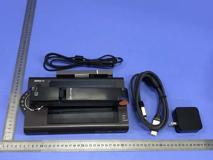
2ABES-KR2109
Jan 02, 2020Ultra10
Equipment Class
DTS - Digital Transmission System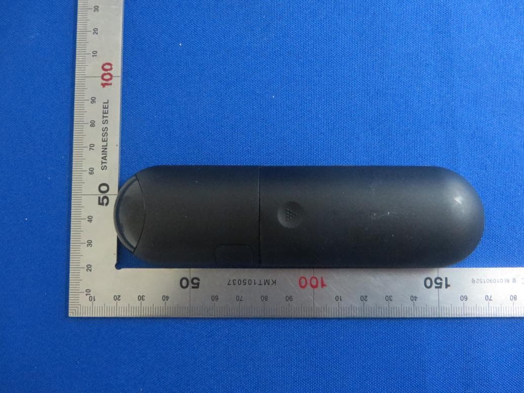
2ABES-ULTRA8
May 25, 2015Remote Control
Equipment Class
DXX - Part 15 Low Power Communication Device Transmitter
2ABES-GURUBOOK5
Oct 21, 2014Gurubook 5/MID
Equipment Class
DTS - Digital Transmission System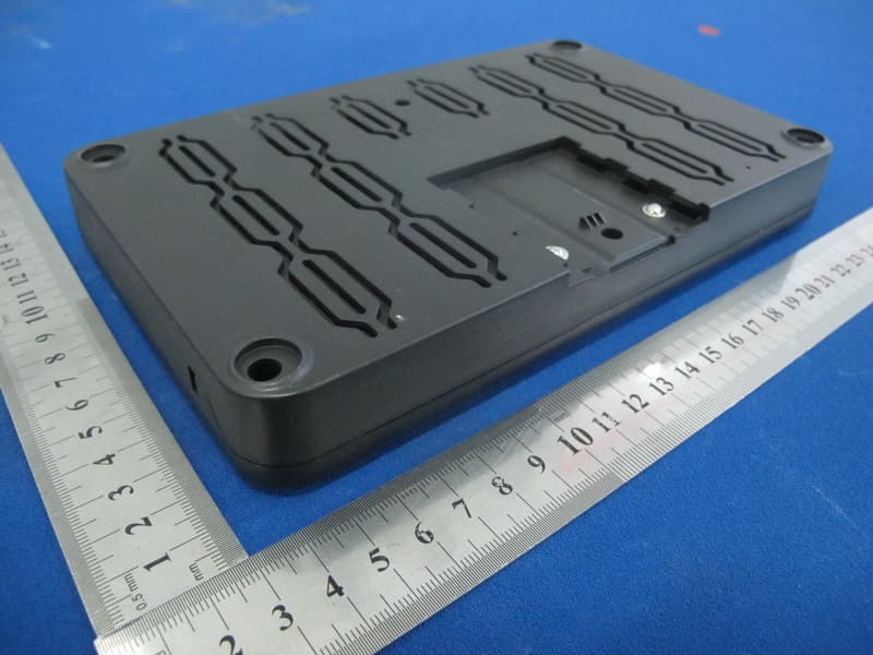
2ABES-AIR
Dec 16, 2013AirStation
Equipment Class
DTS - Digital Transmission System