2ABFD-MDF1019Wireless transceiver module
Mircom Group of Companies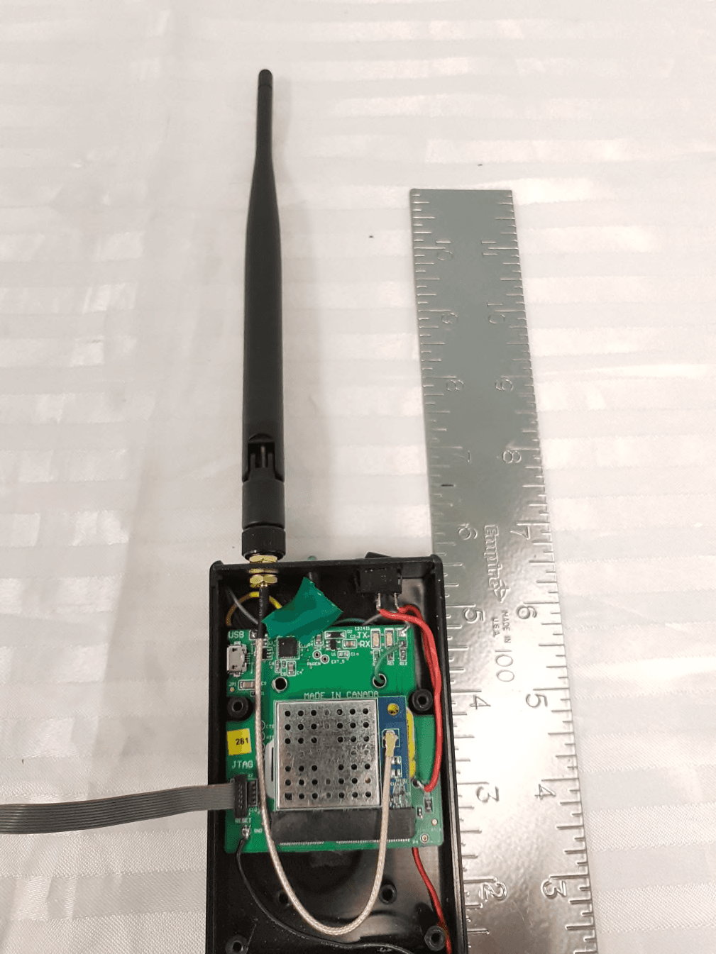
Click to zoom
Application Details
- Equipment Class
- DTS - Digital Transmission System
- Date of Grant
- May 27, 2021
- Application Purpose
- Original Equipment
- Date of Application
- May 27, 2021
- Equipment Note
- Wireless transceiver module
- Frequency Range
- 2405.00000000 - 2480.00000000
- Company
- Mircom Group of Companies
- Country
- Canada
Documents & Files
Document Text
Text extracted from the exhibit documents filed with the FCC. Open a document above to read the original.
Users Manual
Certificates Approved Antenna Types MDF-1019 is approved with a standard 5 dBi dipole antenna. Any antenna of the same type, similar in-band out of band characteris- tics and with the same or less gain can be used without reassessment. In case using antenna of a different type and/or higher gain reassessments and notification to the particular certification authority is required. FCC This device complies with Part 15 of the FCC Rules. Operation is subject to the following two conditions: 1.This device may not cause harmful interference, and 2.This device must accept any interference received, including interference that may cause undesirable operation. Any changes or modifications not expressly approved by Mircom could void the user’s authority to operate the equipment. FCC RF Radiation Exposure Statement: This equipment complies with FCC radiation exposure limits set forth for an uncontrolled environment. End users must follow the specif- ic operating instructions for satisfying RF exposure compliance. This transmitter meets both portable and mobile limits as demonstrated in the RF Exposure Analysis. This transmitter must not be co-located or operating in conjunction with any other antenna or transmitter except in accordance with FCC multi-transmitter product procedures. As long as the condition above is met, further transmitter testing will not be required. However, the OEM integrator is still responsible for testing their end-product for any additional compliance require- ments required with this module installed (for example, digital device emissions, PC peripheral requirements, etc.). OEM Responsibilities to comply with FCC Regulations The MDF-1019 Module has been certified for integration into products only by OEM integrators under the following condition: • The antenna(s) must be installed such that a minimum separation distance of 20 cm is maintained between the radiator (antenna) and all persons at all times. • The transmitter module must not be co-located or operating in conjunction with any other antenna or transmitter except in accord- ance with FCC multi-transmitter product procedures. As long as the conditions above are met, further transmitter testing will not be required. However, the OEM integrator is still responsible for testing their end-product for any additional compliance requirements required with this module installed (for example, digital device emissions, PC peripheral requirements, etc.). Note: In the event that this condition cannot be met (for certain configurations or co-location with another transmitter), then the FCC authorization is no longer considered valid and the FCC ID cannot be used on the final product. In these circumstances, the OEM inte- grator will be responsible for re-evaluating the end product (including the transmitter) and obtaining a separate FCC authorization. End Product Labeling The MDF-1019 Module is labeled with its own FCC ID. If the FCC ID is not visible when the module is installed inside another device, then the outside of the device into which the module is installed must also display a label referring to the enclosed module. In that case, the final end product must be labeled in a visible area with the following: "Contains FCC ID: 2ABFD-MDF1019" The OEM integrator must not provide information to the end user regarding how to install or remove this RF module or change RF related parameters in the user manual of the end product. Innovation, Science and Economic Development Canada ISED (English) This radio transmitter has been approved by ISED to operate with the dipole Pulse W1038. Other antenna types are strictly prohibited for use with this device. This device complies with Industry Canada’s license-exempt RSS standards. Operation is subject to the following two conditions: 1.This device may not cause interference; and 2.This device must accept any interference, including interference that may cause undesired operation of the device. RF Exposure Statement Exception from routine SAR evaluation limits are given in RSS-102 Issue 5. MDF-1019 meets the given requirements when the minimum separation distance to human body 20 c m. RF exposure or SAR evaluation is not required when the separation distance is 20 c m or more. If the separation distance is less than 20 cm the OEM integrator is responsible for evaluating the SAR. OEM Responsibilities to comply with ISED Regulations The MDF-1019 Module has been certified for integration into products only by OEM integrators under the following conditions: • The antenna(s) must be installed such that a minimum separation distance of 20 cm is maintained between the radiator (antenna) and all persons at all times. • The transmitter module must not be co-located or operating in conjunction with any other antenna or transmitter. As long as the two conditions above are met, further transmitter testing will not be required. However, the OEM integrator is still respon- sible for testing their end-product for any additional compliance requirements required with this module installed (for example, digital device emissions, PC peripheral requirements, etc.). Note: In the event that these conditions cannot be met (for certain configurations or co-location with another transmitter), then the IC authorization is no longer considered valid and the IC ID cannot be used on the final product. In these circumstances, the OEM integra- tor will be responsible for re-evaluating the end product (including the transmitter) and obtaining a separate IC authorization. End Product Labeling The MDF-1019 module is labeled with its own IC ID. If the IC ID is not visible when the module is installed inside another device, then the outside of the device into which the module is installed must also display a label referring to the enclosed module. In that case, the final end product must be labeled in a visible area with the following: "Contains IC: 1156A-MDF1019" The OEM integrator has to be aware not to provide informati…
Text truncated - open the document above for the full version.
Cover Letter(s)
Canada / International: Mircom Technologies Ltd. | 25 Interchange Way | Vaughan (Toronto), ON L4K 5W3 | Tel: 905.660.4655 | Fax: 905.660.4113 U.S.A.: MGC Systems Corp. | 4575 Witmer Industrial Estates | Niagara Falls, NY 14305 | Tel: 888.660.4655 | Fax: 888.660.4113 www.mircom.com 12 May 2021 TUV SUD America Inc. 10 Centennial Drive Peabody, MA 01960, USA Re: Agency Authorization Dear Sir or Madam: We, Mircom Technologies Ltd., hereby authorize Amir Emami of TUV SUD Canada Inc., 11 Gordon Collins Drive, Gormley, L0H 1G0, Canada; 905-883-7255 to act as our agent in all matters relating to applications for equipment authorization, including the signing of all documents relating to these matters. Sincerely, Mr. Laurie E. Eisner, P.Eng., MASc, VP Product Development 905 660 4655 x2060 [email protected] http://www.mircom.com/
Cover Letter(s)
Canada / International: Mircom Technologies Ltd. | 25 Interchange Way | Vaughan (Toronto), ON L4K 5W3 | Tel: 905.660.4655 | Fax: 905.660.4113 U.S.A.: MGC Systems Corp. | 4575 Witmer Industrial Estates | Niagara Falls, NY 14305 | Tel: 888.660.4655 | Fax: 888.660.4113 www.mircom.com 12 May 2021 Federal Communications Commission Equipment Authorization Branch 7435 Oakland Mills Road Columbia, MD 21046 Modular Approval Request FCC ID: 2ABFD-MDF1019 The following attestation addresses the requirements to support modular approval: Modular approval requirement Yes (provide brief statement) No * (a) The radio elements must have the radio frequency circuitry shielded. Physical components and tuning capacitor(s) may be located external to the shield, but must be on the module assembly The radio elements covered with EMI shield. On the schematic shield has designator EMS1 (b) The module must have buffered modulation/data inputs to ensure that the device will comply with Part 15 requirements with any type of input signal MDF-1019 based on TI chip CC1352P which has buffered modulation (c) The module must contain power supply regulation on the module The module has LDO. On the schematic LDO has designator U2 (d) The module must contain a permanently attached antenna, or contain a unique antenna connector, and be marketed and operated only with specific antenna(s), per Sections 15.203, 15.204(b), 15.204(c), 15.212(a), 2.929(b) The module has UMC connector (P2). Whip antenna ANT-011 permanently connected to P2 (e) The module must demonstrate compliance in a stand-alone configuration MDF-1019 demonstrated compliance in a stand-alone configuration (f) The module must be labelled with its permanently affixed FCC ID label, or use an electronic display (See KDB Publication 784748 about labelling requirements) MDF-1019 has the label Canada / International: Mircom Technologies Ltd. | 25 Interchange Way | Vaughan (Toronto), ON L4K 5W3 | Tel: 905.660.4655 | Fax: 905.660.4113 U.S.A.: MGC Systems Corp. | 4575 Witmer Industrial Estates | Niagara Falls, NY 14305 | Tel: 888.660.4655 | Fax: 888.660.4113 www.mircom.com (g) The module must comply with all specific rules applicable to the transmitter. The grantee must provide comprehensive instructions to explain compliance requirements MDF-1019 comply with all rules Sincerely, Mr. Laurie E. Eisner, P.Eng., MASc, VP Product Development 905 660 4655 x2060 [email protected] http://www.mircom.com/ Canada / International: Mircom Technologies Ltd. | 25 Interchange Way | Vaughan (Toronto), ON L4K 5W3 | Tel: 905.660.4655 | Fax: 905.660.4113 U.S.A.: MGC Systems Corp. | 4575 Witmer Industrial Estates | Niagara Falls, NY 14305 | Tel: 888.660.4655 | Fax: 888.660.4113 www.mircom.com Modular approval requirement Yes (provide brief statement) No * (h) The module must comply with RF exposure requirements MDF-1019 comply with RF exposure * Please provide a detailed explanation if the answer is “No.” Canada / International: Mircom Technologies Ltd. | 25 Interchange Way | Vaughan (Toronto), ON L4K 5W3 | Tel: 905.660.4655 | Fax: 905.660.4113 U.S.A.: MGC Systems Corp. | 4575 Witmer Industrial Estates | Niagara Falls, NY 14305 | Tel: 888.660.4655 | Fax: 888.660.4113 www.mircom.com
Cover Letter(s)
Canada / International: Mircom Technologies Ltd. | 25 Interchange Way | Vaughan (Toronto), ON L4K 5W3 | Tel: 905.660.4655 | Fax: 905.660.4113 U.S.A.: MGC Systems Corp. | 4575 Witmer Industrial Estates | Niagara Falls, NY 14305 | Tel: 888.660.4655 | Fax: 888.660.4113 www.mircom.com 12 May 2021 Federal Communications Commission Equipment Authorization Branch 7435 Oakland Mills Road Columbia, MD 21046 Confidentiality Request Re: FCC ID: 2ABFD-MDF1019 Dear Sir or Madam: Pursuant to Sections 0.457(d)(1)(ii) and 0.459 of the Commission’s Rules, Mircom Group of Companies hereby requests permanent confidential treatment of information accompanying this application as outlined below: Schematics Bill of Materials/Parts List Block Diagrams Theory of Operation Mircom Technologies Ltd. also hereby requests short-term confidential treatment of information accompanying this application as outlined below for a period of period of 90 days: Internal Photos External Photos User Manual Test Set-up Photographs The above materials contain trade secrets and proprietary information not customarily released to the public. The public disclosure of these matters might be harmful to the Applicant and provide unjustified benefits to its competitors. Canada / International: Mircom Technologies Ltd. | 25 Interchange Way | Vaughan (Toronto), ON L4K 5W3 | Tel: 905.660.4655 | Fax: 905.660.4113 U.S.A.: MGC Systems Corp. | 4575 Witmer Industrial Estates | Niagara Falls, NY 14305 | Tel: 888.660.4655 | Fax: 888.660.4113 www.mircom.com The Applicant understands that pursuant to Rule 0.457(d)(1)(ii), disclosure of this Application and all accompanying materials will not be made before the date of the Grant for this Application. Sincerely, Mr. Laurie E. Eisner, P.Eng., MASc, VP Product Development 905 660 4655 x2060 [email protected] http://www.mircom.com/ Canada / International: Mircom Technologies Ltd. | 25 Interchange Way | Vaughan (Toronto), ON L4K 5W3 | Tel: 905.660.4655 | Fax: 905.660.4113 U.S.A.: MGC Systems Corp. | 4575 Witmer Industrial Estates | Niagara Falls, NY 14305 | Tel: 888.660.4655 | Fax: 888.660.4113 www.mircom.com
External Photos
Report File #: 7169009386R-000 © TÜV SÜD Canada Inc. This test report shall not be reproduced except in full, without written approval of TÜV SÜD Canada Inc. Exhibit: External Photos FCC ID: 2ABFD-MDF1019 IC: 1156A-MDF1019 Client Mircom Technologies Ltd. Product MDF-1019 Standard(s) RSS 247 Issue 2:2017 FCC Part 15 Subpart 15.247 Page 2 of 2 Report Issued: 5/25/2021 Report File #: 7169009386R-000 © TÜV SÜD Canada Inc. This test report shall not be reproduced except in full, without written approval of TÜV SÜD Canada Inc. Figure 1 – EUT External Photo with Shield and Antenna (Installed on Development Board)
ID Label/Location Info
Report File #: 7169009386R-000 © TÜV SÜD Canada Inc. This test report shall not be reproduced except in full, without written approval of TÜV SÜD Canada Inc. Exhibit: Sample Label and Location FCC ID: 2ABFD-MDF1019 IC: 1156A-MDF1019 Client Mircom Technologies Ltd. Product MDF-1019 Standard(s) RSS 247 Issue 2:2017 FCC Part 15 Subpart 15.247 Page 2 of 2 Report Issued: 5/25/2021 Report File #: -000 © TÜV SÜD Canada Inc. This test report shall not be reproduced except in full, without written approval of TÜV SÜD Canada Inc. FCC ID: 2ABFD-MDF1019 IC: 1156A-MDF1019 M/N: MDF-1019
Internal Photos
Report File #: 7169009386R-000 © TÜV SÜD Canada Inc. This test report shall not be reproduced except in full, without written approval of TÜV SÜD Canada Inc. Exhibit: Internal Photos FCC ID: 2ABFD-MDF1019 IC: 1156A-MDF1019 Client Mircom Technologies Ltd. Product MDF-1019 Standard(s) RSS 247 Issue 2:2017 FCC Part 15 Subpart 15.247 Page 2 of 4 Report Issued: 5/25/2021 Report File #: 7169009386R-000 © TÜV SÜD Canada Inc. This test report shall not be reproduced except in full, without written approval of TÜV SÜD Canada Inc. Figure 1 – EUT Internal Photo Front Client Mircom Technologies Ltd. Product MDF-1019 Standard(s) RSS 247 Issue 2:2017 FCC Part 15 Subpart 15.247 Page 3 of 4 Report Issued: 5/25/2021 Report File #: 7169009386R-000 © TÜV SÜD Canada Inc. This test report shall not be reproduced except in full, without written approval of TÜV SÜD Canada Inc. Figure 2 – EUT Internal Photo Back Client Mircom Technologies Ltd. Product MDF-1019 Standard(s) RSS 247 Issue 2:2017 FCC Part 15 Subpart 15.247 Page 4 of 4 Report Issued: 5/25/2021 Report File #: 7169009386R-000 © TÜV SÜD Canada Inc. This test report shall not be reproduced except in full, without written approval of TÜV SÜD Canada Inc. Figure 3 – EUT Internal Photo - Antenna
RF Exposure Info
Report File #: 7169009386R-000 © TÜV SÜD Canada Inc. This test report shall not be reproduced except in full, without written approval of TÜV SÜD Canada Inc. Exhibit: RF Exposure – FCC FCC ID: 2ABFD-MDF1019 Client Mircom Technologies Ltd. Product MDF-1019 Standard(s) FCC Part 15 Subpart 15.247 FCC KDB 447498:2015 Page 2 of 4 Report Issued: 5/25/2021 Report File #: 7169009386R-000 © TÜV SÜD Canada Inc. This test report shall not be reproduced except in full, without written approval of TÜV SÜD Canada Inc. RF Exposure – FCC The device is a mobile device intended to generally be used in such a way that a separation distance of at least 20 centimeters is normally maintained between the transmitter's radiating structure and the body of the user or nearby persons. General SAR test exclusion guidance: As per FCC KDB 447498 Section 4.3.1 b), the SAR Test Exclusion Threshold for 100 MHz to 6 GHz at test separation distances > 50 mm is determined by: 1) {[Power allowed at numeric threshold for 50 mm)] + [(test separation distance – 50 mm) (f(MHz)/150)]} mW, for 100 MHz to 1500 MHz 2) {[Power allowed at numeric threshold for 50 mm)] + [(test separation distance – 50 mm)*10]} mW, for > 1500 MHz and ≤ 6 GHz Where: Power allowed at numeric threshold for 50 mm (for 1-g SAR) is given by: [(max. power of channel, including tune-up tolerance, mW)/(min. test separation distance, mm)] [√f (GHz) ] ≤ 3.0 (max power of channel, including tune-up tolerance, mW) ≤ [3.0 / √f (GHz) ] * [min. test separation distance, mm] f (GHz) is the RF channel transmit frequency in GHz Client Mircom Technologies Ltd. Product MDF-1019 Standard(s) FCC Part 15 Subpart 15.247 FCC KDB 447498:2015 Page 3 of 4 Report Issued: 5/25/2021 Report File #: 7169009386R-000 © TÜV SÜD Canada Inc. This test report shall not be reproduced except in full, without written approval of TÜV SÜD Canada Inc. SAR Calculations: 2405 – 2480 MHz DTS transmitter Power allowed at numeric threshold for 50 mm: (max power of channel, including tune-up tolerance, mW) ≤ [3.0 / √(2.480 GHz)] * [50 mm] (max power of channel, including tune-up tolerance, mW) ≤ 95.25 mW Therefore SAR Exclusion for 200 mm test distance is: {[Power allowed at numeric threshold for 50 mm)] + [(test separation distance – 50 mm)*10]} mW, for > 1500 MHz and ≤ 6 GHz = [95.25 mW] + [(200 mm – 50 mm) * 10] = 1595 mW The EUT meets the SAR Exclusion Threshold. Peak conducted power of DTS transmitter was measured to be 24 mW which is below the 1595mW threshold. Client Mircom Technologies Ltd. Product MDF-1019 Standard(s) FCC Part 15 Subpart 15.247 FCC KDB 447498:2015 Page 4 of 4 Report Issued: 5/25/2021 Report File #: 7169009386R-000 © TÜV SÜD Canada Inc. This test report shall not be reproduced except in full, without written approval of TÜV SÜD Canada Inc. Radiofrequency Radiation Exposure Evaluation: Mobile Devices Mobile devices shall be evaluated for RF radiation exposure according to the provisions of FCC §2.1091 and the MPE guidelines identified in FCC §1.1310. As per FCC §1.1310 Table 1(B), the limit for Maximum Permissible Exposure (MPE) to radiofrequency electromagnetic fields for General Population/Uncontrolled Exposure in the frequency range of 300 MHz to 1.5 GHz is f/1500 mW/cm 2 and in the frequency range of 1.5GHz to 100GHz is 1.0 mW/cm 2 . Where f = frequency in MHz. The power density formula is given by: P d = (P out *G) / (4*pi*R 2 ) Where, P d = Power density in mW/cm 2 P out = Conducted output power to antenna in mW G = Numeric Antenna Gain Pi = 3.1416 R = Separation distance in cm MPE Calculation: 2405 – 2480 MHz DTS transmitter The DTS transmitter has a maximum conducted output power of 13.81dBm or 24.04mW and an antenna gain of 5dBi or 3.16 numerically. For a distance of 20cm, the power density is: P d = (24.04mW * 3.16) / (4 * 3.1416 * (20cm) 2 ) P d = 0.015 mW/cm 2 The device passes the requirement. The calculated power density of 0.015 mW/cm 2 is below the 1.0 mW/cm 2 limit.
Test Report
Registration # 6844A-3 Testing Laboratory Certificate #2955.02 R-14023, G-20072 C-14498, T-20060 Registration # CA6844 Page 1 of 60 Report Issued: 5/26/2021 Report File #: 7169009386R-000 © TÜV SÜD Canada Inc. This test report shall not be reproduced except in full, without written approval of TÜV SÜD Canada Inc. FCC 15 247 Rev3 EMC & RF Test Report As per RSS-247 Issue 2:2017 & FCC Part 15 Subpart 15.247 Unlicensed Intentional Radiators on the MDF-1019 Zigbee Module Issued by: TÜV SÜD Canada Inc. 11 Gordon Collins Dr, Gormley, ON, L0H 1G0 Canada Ph: (905) 883-7255 Testing produced for See Appendix A for full client & EUT details. Prepared by: Amir Emami, Project Engineer Reviewed by: Min Xie, Sr. Project Engineer Client Mircom Technologies Ltd. Product MDF-1019 Standard(s) RSS 247 Issue 2:2017 FCC Part 15 Subpart 15.247 Page 2 of 60 Report Issued: 5/26/2021 Report File #: 7169009386R-000 © TÜV SÜD Canada Inc. This test report shall not be reproduced except in full, without written approval of TÜV SÜD Canada Inc. Table of Contents Table of Contents ................................................................................................................... 2 Report Scope .......................................................................................................................... 3 Summary ................................................................................................................................ 4 Test Results Summary ....................................................................................................... 5 Notes, Justifications, or Deviations ................................................................................... 6 Sample Calculation(s) ........................................................................................................ 6 Applicable Standards, Specifications and Methods ............................................................... 7 Document Revision Status ..................................................................................................... 8 Definitions and Acronyms ..................................................................................................... 9 Testing Facility .................................................................................................................... 10 Calibrations and Accreditations ....................................................................................... 10 Testing Environmental Conditions and Dates ................................................................. 11 Detailed Test Results Section .............................................................................................. 12 6dB Bandwidth of Digitally Modulated Systems ............................................................ 13 Maximum Peak Envelope Conducted Power .................................................................. 17 Antenna Spurious Conducted Emissions (-20 dBc Requirement) ................................... 22 Transmitter Spurious Radiated Emissions ....................................................................... 32 Power Spectral Density .................................................................................................... 53 Appendix A – EUT Summary .............................................................................................. 58 Appendix B – EUT and Test Setup Photos .......................................................................... 60 Client Mircom Technologies Ltd. Product MDF-1019 Standard(s) RSS 247 Issue 2:2017 FCC Part 15 Subpart 15.247 Page 3 of 60 Report Issued: 5/26/2021 Report File #: 7169009386R-000 © TÜV SÜD Canada Inc. This test report shall not be reproduced except in full, without written approval of TÜV SÜD Canada Inc. Report Scope This report addresses the EMC verification testing and test results of the MDF-1019 Zigbee Module and is herein referred to as EUT (Equipment Under Test). The EUT was tested for compliance against the following standards: RSS-247 Issue 2:2017 FCC Part 15 Subpart C 15.247 Test procedures, results, justifications, and engineering considerations, if any, follow later in this report. This report does not imply product endorsement by any government, accreditation agency, or TÜV SÜD Canada Inc. Opinions or interpretations expressed in this report, if any, are outside the scope of TÜV SÜD Canada Inc. accreditations. Any opinions expressed do not necessarily reflect the opinions of TÜV SÜD Canada Inc., unless otherwise stated. Client Mircom Technologies Ltd. Product MDF-1019 Standard(s) RSS 247 Issue 2:2017 FCC Part 15 Subpart 15.247 Page 4 of 60 Report Issued: 5/26/2021 Report File #: 7169009386R-000 © TÜV SÜD Canada Inc. This test report shall not be reproduced except in full, without written approval of TÜV SÜD Canada Inc. Summary The results contained in this report relate only to the item(s) tested. EUT: MDF-1019 Zigbee Module FCC Certification #, FCC ID: 2ABFD-MDF1019 Industry Canada Certification #, IC: 1156A-MDF1019 EUT passed all tests performed Yes Tests conducted by Amir Emami Report reviewed by Min Xie For testing dates, see "Testing Environmental Conditions and Dates". Client Mircom Technologies Ltd. Product MDF-1019 Standard(s) RSS 247 Issue 2:2017 FCC Part 15 Subpart 15.247 Page 5 of 60 Report Issued: 5/26/2021 Report File #: 7169009386R-000 © TÜV SÜD Canada Inc. This test report shall not be reproduced except in full, without written approval of TÜV SÜD Canada Inc. Test Results Summary Standard/Method Description Class/Limit Result FCC 15.203 Antenna Requirement Unique Pass See Justification FCC 15.205 RSS-GEN (Table 6) Restricted Bands for Intentional Operation QuasiPeak Average Pass FCC 15.207 RSS-GEN (Table 3) Power Line Conducted Emissions QuasiPeak Average Pass FCC 15.209 RSS-GEN (Table 4) Spurious Radiated Emissions QuasiPeak Average Pass FCC 15.247(a)2 RSS-247 5.2(a) 6 dB Bandwidth > 500 kHz Pass FCC 15.247(b)2 RSS-2475.…
Text truncated - open the document above for the full version.
Test Setup Photos
Report File #: 7169009386RF-000 © TÜV SÜD Canada Inc. This test report shall not be reproduced except in full, without written approval of TÜV SÜD Canada Inc. Exhibit: Test Setup Photos FCC ID: 2ABFD-MDF1019 IC: 1156A-MDF1019 Client Mircom Group of Companies Product MDF-1019 Standard(s) RSS 247 Issue 2:2017 FCC Part 15 Subpart 15.247 Page 2 of 9 Report Issued: 5/25/2021 Report File #: 7169009386RF-000 © TÜV SÜD Canada Inc. This test report shall not be reproduced except in full, without written approval of TÜV SÜD Canada Inc. Figure 1 ‒ EUT Close Up (Controlled via Development Board) Client Mircom Group of Companies Product MDF-1019 Standard(s) RSS 247 Issue 2:2017 FCC Part 15 Subpart 15.247 Page 3 of 9 Report Issued: 5/25/2021 Report File #: 7169009386RF-000 © TÜV SÜD Canada Inc. This test report shall not be reproduced except in full, without written approval of TÜV SÜD Canada Inc. Figure 2 ‒ Radiated Emissions Setup X-Axis Client Mircom Group of Companies Product MDF-1019 Standard(s) RSS 247 Issue 2:2017 FCC Part 15 Subpart 15.247 Page 4 of 9 Report Issued: 5/25/2021 Report File #: 7169009386RF-000 © TÜV SÜD Canada Inc. This test report shall not be reproduced except in full, without written approval of TÜV SÜD Canada Inc. Figure 3 ‒ Radiated Emissions Setup 9kHz to 30MHz Client Mircom Group of Companies Product MDF-1019 Standard(s) RSS 247 Issue 2:2017 FCC Part 15 Subpart 15.247 Page 5 of 9 Report Issued: 5/25/2021 Report File #: 7169009386RF-000 © TÜV SÜD Canada Inc. This test report shall not be reproduced except in full, without written approval of TÜV SÜD Canada Inc. Figure 4 ‒ Radiated Emissions Setup 30MHz to 1GHz Note: As per ANSI C63.10-2013 Clause 6.3.1, below 1GHz, the height of the EUT was set to 80cm. Above 1GHz, the height was raised to 1.5m. Client Mircom Group of Companies Product MDF-1019 Standard(s) RSS 247 Issue 2:2017 FCC Part 15 Subpart 15.247 Page 6 of 9 Report Issued: 5/25/2021 Report File #: 7169009386RF-000 © TÜV SÜD Canada Inc. This test report shall not be reproduced except in full, without written approval of TÜV SÜD Canada Inc. Figure 5 ‒ Radiated Emissions Setup 1GHz to 6GHz Note: As per ANSI C63.10-2013 Clause 6.3.1, above 1GHz, the height of the EUT was set to 1.5m. Client Mircom Group of Companies Product MDF-1019 Standard(s) RSS 247 Issue 2:2017 FCC Part 15 Subpart 15.247 Page 7 of 9 Report Issued: 5/25/2021 Report File #: 7169009386RF-000 © TÜV SÜD Canada Inc. This test report shall not be reproduced except in full, without written approval of TÜV SÜD Canada Inc. Figure 6 ‒ Radiated Emissions Setup 6GHz to 18GHz Client Mircom Group of Companies Product MDF-1019 Standard(s) RSS 247 Issue 2:2017 FCC Part 15 Subpart 15.247 Page 8 of 9 Report Issued: 5/25/2021 Report File #: 7169009386RF-000 © TÜV SÜD Canada Inc. This test report shall not be reproduced except in full, without written approval of TÜV SÜD Canada Inc. Figure 7 ‒ Radiated Emissions Setup 18GHz to 26GHz Client Mircom Group of Companies Product MDF-1019 Standard(s) RSS 247 Issue 2:2017 FCC Part 15 Subpart 15.247 Page 9 of 9 Report Issued: 5/25/2021 Report File #: 7169009386RF-000 © TÜV SÜD Canada Inc. This test report shall not be reproduced except in full, without written approval of TÜV SÜD Canada Inc. Figure 8 ‒ Antenna Port Conducted Emissions Setup
Contact Information
Applicant
Laurie E Eisner
Test Firm
TUV SUD CANADA (Gormley)William (Mac) Elliott
[email protected]813-284-2736
Technical Specifications
| # | Rule Parts | Frequency Range | Power Output |
|---|---|---|---|
| 1 | 15C | 2.40 GHz - 2.48 GHz | 24.00 mW |
Other Applications from Mircom Group of Companies
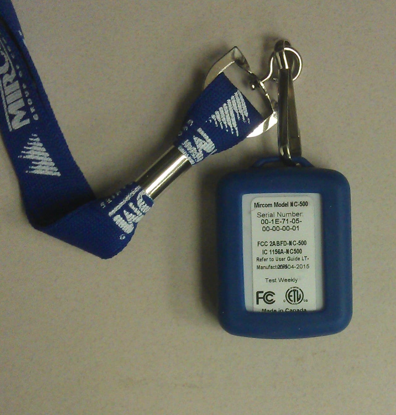
2ABFD-NC-500
Nov 09, 2015NC-500 MiCare Pendant
Equipment Class
DTS - Digital Transmission System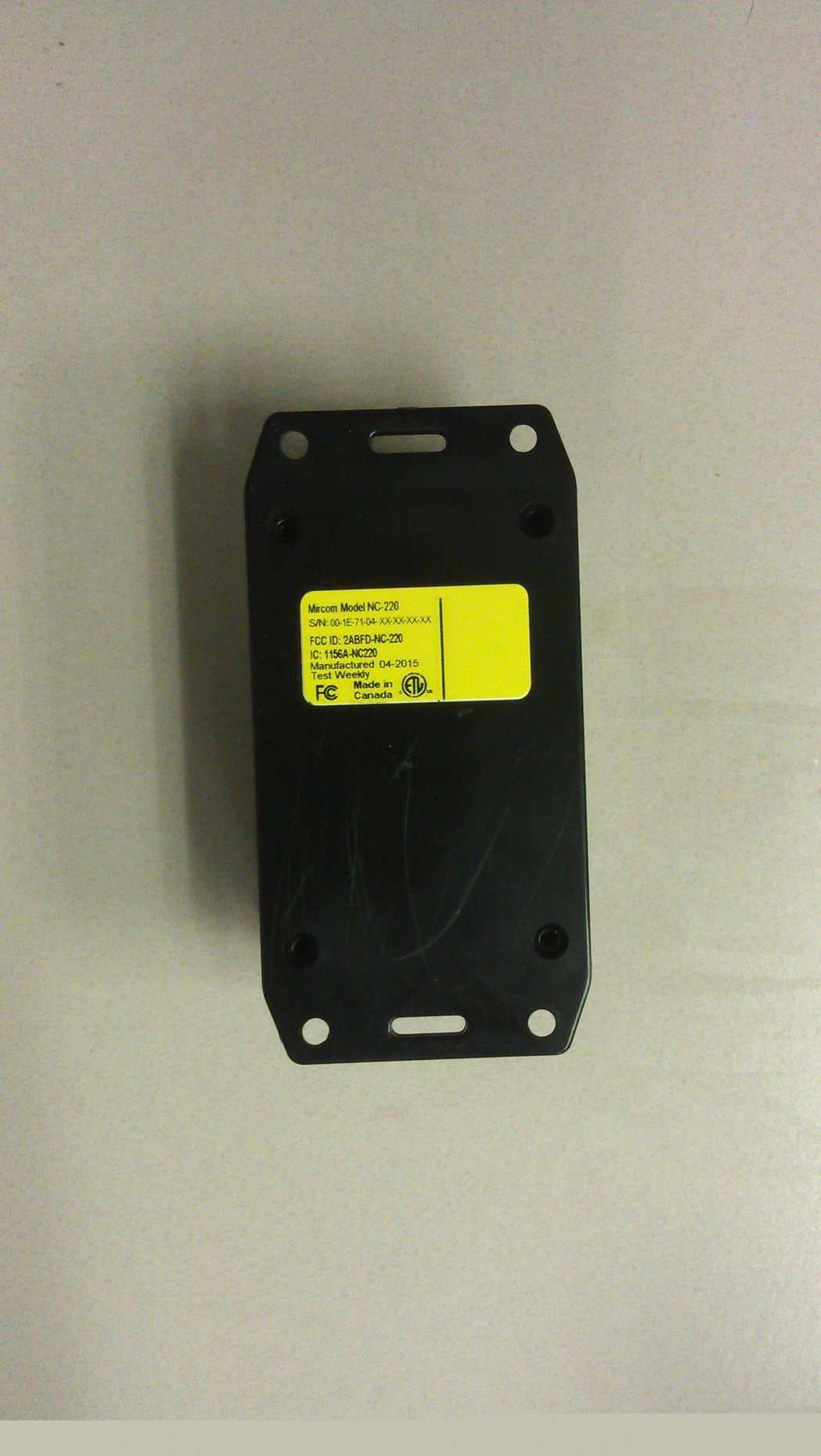
2ABFD-NC-220
Nov 09, 2015NC-220 MiCare ZF3
Equipment Class
DTS - Digital Transmission System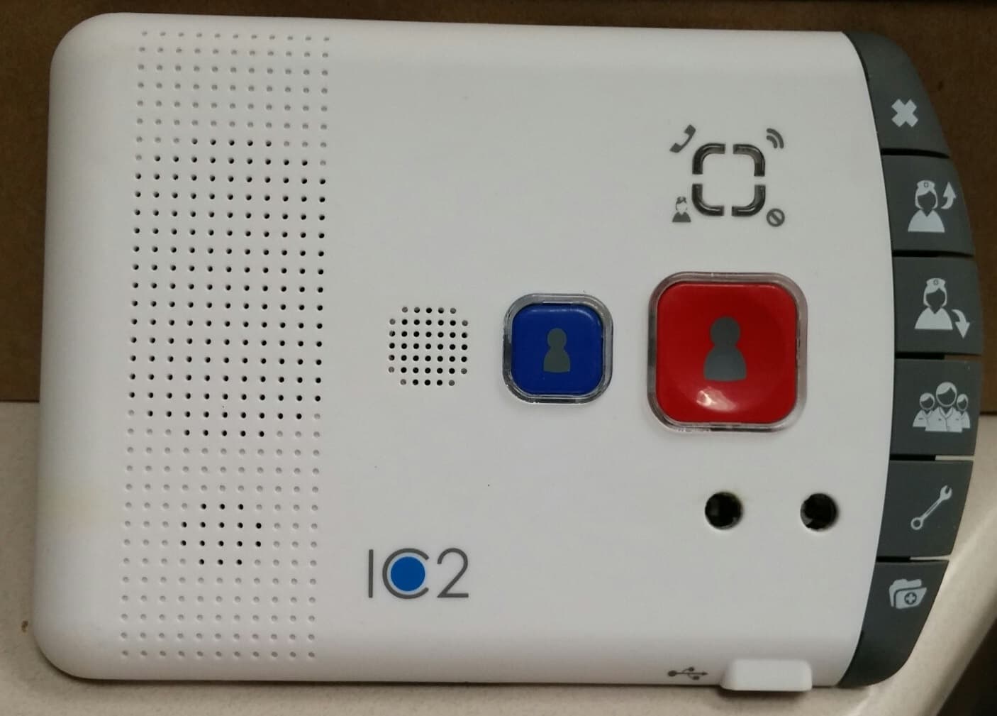
2ABFD-NC-2000
Nov 09, 2015NC-2000 MiCare Patient Unit
Equipment Class
DTS - Digital Transmission System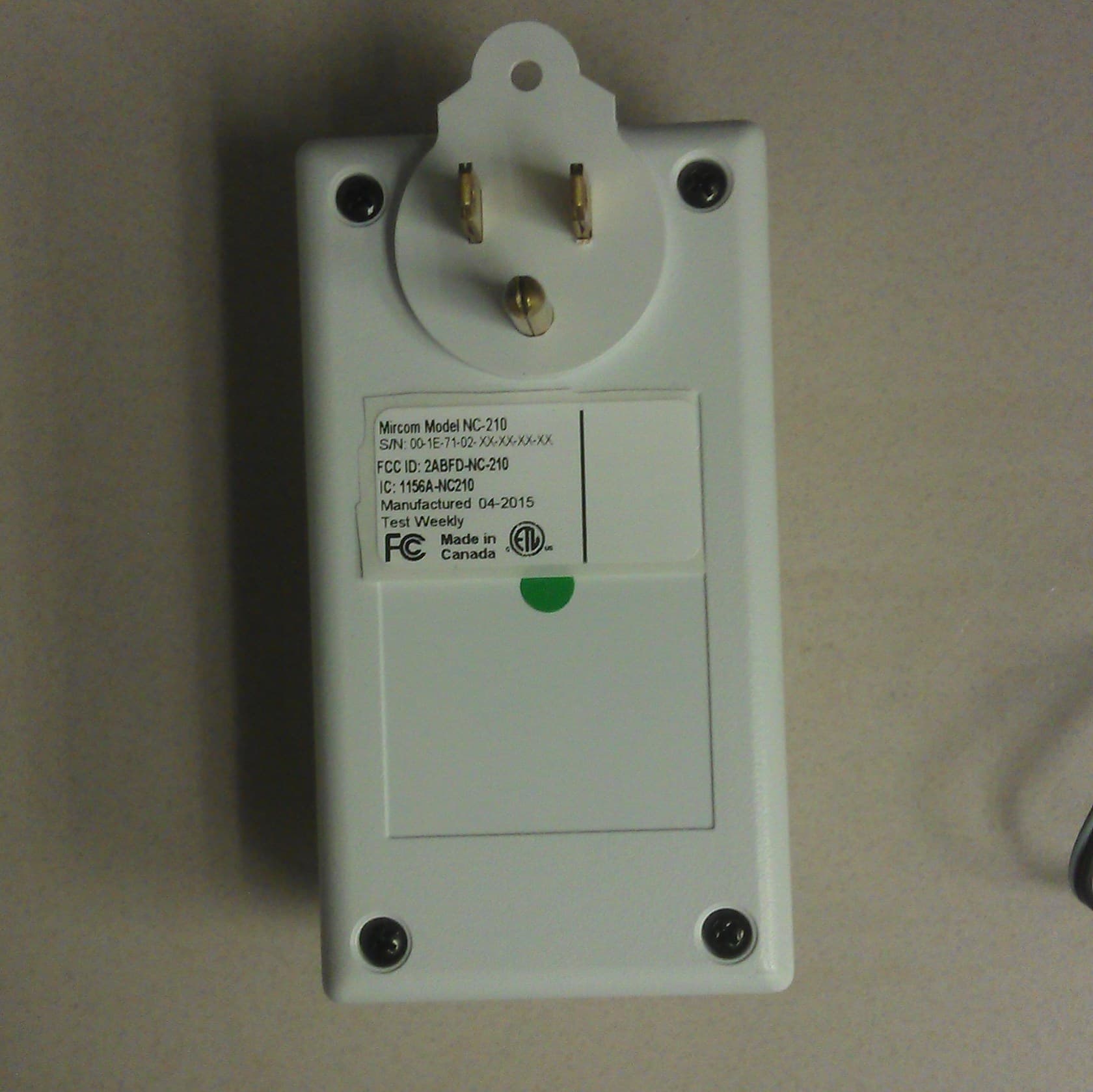
2ABFD-NC-210
Nov 09, 2015NC-210 MiCare Beacon
Equipment Class
DTS - Digital Transmission System
2ABFD-NC-103
Nov 08, 2015NC-103 MiCare Pull Station
Equipment Class
DTS - Digital Transmission System