2ABFD-NC-2000NC-2000 MiCare Patient Unit
Mircom Group of Companies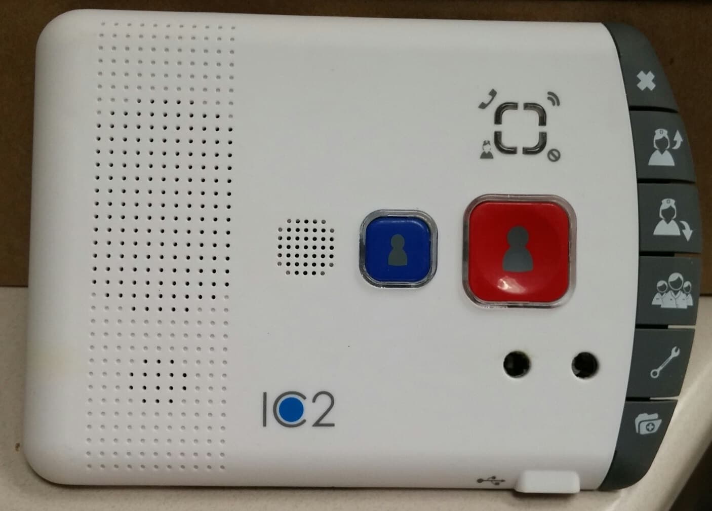
Click to zoom
Application Details
- Equipment Class
- DTS - Digital Transmission System
- Date of Grant
- Nov 09, 2015
- Application Purpose
- Original Equipment
- Date of Application
- Nov 09, 2015
- Equipment Note
- NC-2000 MiCare Patient Unit
- Frequency Range
- 2405.00000000 - 2480.00000000
- Company
- Mircom Group of Companies
- Country
- Canada
Documents & Files
Document Text
Text extracted from the exhibit documents filed with the FCC. Open a document above to read the original.
Users Manual
Nurse Call System LT-2076 Rev. 1 .2 September 2015 User Guide For the latest compatability information visit www.mircom.com/deviceguide LT-2076 Rev 1.23 Table of Contents 1.0Introduction 5 1.1About this User Guide .................................................................................................... 5 1.2Contact Us ..................................................................................................................... 6 1.2.1General Inquiries ............................................................................................................ 6 1.2.2Customer Service .......................................................................................................... 6 1.2.4Website .......................................................................................................................... 6 2.0Dashboard 7 2.1Campus, Building, Wing, and Floor ............................................................................... 7 2.2Alerts .............................................................................................................................. 8 2.3Alerts List ....................................................................................................................... 8 2.3.1Speaking to the patient .................................................................................................. 8 2.4Activity ............................................................................................................................ 9 3.0Manage My Shift 10 3.1Logging in to Dashboard ................................................................................................ 10 3.2Starting your Shift .......................................................................................................... 10 3.3Recording Breaks .......................................................................................................... 10 3.4Ending your Shift ............................................................................................................ 10 4.0Patients and Attendants 11 4.1Patients .......................................................................................................................... 11 4.1.1Check Ins ....................................................................................................................... 11 4.2Attendants ...................................................................................................................... 11 5.0Active Alerts 12 6.0Warranty and Warning Information 13 6.1Warning Please Read Carefully ..................................................................................... 13 6.2Note to Installers ............................................................................................................ 13 6.3System Failures ............................................................................................................. 13 6.3.1Inadequate Installation ................................................................................................... 13 6.3.2Power Failure ................................................................................................................. 13 6.3.3Failure of Replaceable Batteries .................................................................................... 13 6.3.4Compromise of Radio Frequency (Wireless) Devices ................................................... 14 6.3.5System Users ................................................................................................................. 14 4LT-2076 Rev 1.2 6.3.6Automatic Alarm Initiating Devices ................................................................................. 14 6.3.7Software ......................................................................................................................... 14 6.3.8Alarm Notification ........................................................................................................... 14 6.3.9Telephone Lines ............................................................................................................. 14 6.3.10Insufficient Time ............................................................................................................. 15 6.3.11Component Failure ......................................................................................................... 15 6.3.12Inadequate Testing ........................................................................................................ 15 6.3.13Security and Insurance .................................................................................................. 15 6.4Limited Warranty ............................................................................................................ 15 6.4.1International Warranty .................................................................................................... 15 6.4.2Conditions to Void Warranty .......................................................................................... 15 6.5Warranty Procedure ....................................................................................................... 16 6.6Disclaimer of Warranties ................................................................................................ 16 6.7Out of Warranty Repairs ................................................................................................ 16 7.0Special Notices 18 7.1Industry Canada Notice .................................................................................................. 18 7.2FCC Notice ..................................................................................................................... 18 LT-2076 Rev 1.25 1.0 Introduction 1.1About this User Guide This user guide describes how attendants use the Dashboard Nursing Station software (Dashboard). With Dashboard, attendants can manage their shifts, get information about patients, find other …
Text truncated - open the document above for the full version.
Test Report
Emissions Report for Mircom Technologies on the NC-2000 (originally tested as Igeacom II) Page 1 of 60 EMISSIONS TEST REPORT Report Number: 101930181BOX-001b Project Number: G101930181 Report Issue Date: 03/26/2015 Product Designation: NC-2000 (originally tested as Igeacom II) Standards: CFR47 FCC Part 15 Subpart C 15.247:2015 CFR47 FCC Part 15 Subpart B:2015 IC RSS-247 Issue 1 May 2015 IC RSS-Gen Issue 4 November 2014 IC ICES-003 Issue 5 August 2012 IC RSS-102 Issue 5 March 2015 updated December 2010 Tested by: Client: Intertek Testing Services NA, Inc. 70 Codman Hill Road Boxborough, MA 01719 Mircom Technologies Ltd. 25 Interchange Way Vaughan ON L4K 5W3 Canada Testing was originally performed for IGEACare Solutions Inc. 163 Rivalda Road North York M9M 2M7 Canada Report prepared by Reviewer Report reviewed by Vathana F. Ven / Staff Engineer, EMC Kouma Sinn / Staff Engineer, EMC Intertek Report Number: 101930181BOX-001b Issued: 03/26/2015 Emissions Report for Mircom Technologies on the NC-2000 (originally tested as Igeacom II) Page 2 of 60 1 Introduction and Conclusion The tests indicated in section 2.0 were performed on the product constructed as described in section 4.0. The remaining test sections are the verbatim text from the actual data sheets used during the investigation. These test sections include the test name, the specified test Method, a list of the actual Test Equipment Used, documentation Photos, Results and raw Data. No additions, deviations, or exclusions have been made from the standard(s) unless specifically noted. Based on the results of our investigation, we have concluded the product tested complies with the requirements of the standard(s) indicated. The results obtained in this test report pertain only to the item(s) tested. 2 Test Summary Section Test full name Result 3 Client Information 4 Description of Equipment Under Test 5 System Setup and Method 6 RF Output Power, Duty Cycle, and Human RF Exposure ( CFR47 FCC Part 15 Subpart C 15.247(b)(3), KDB 558074, IC RSS-247 Issue 1 May 2015 5.4(4), IC RSS-102 Issue 5 March 2015) Pass 7 6 dB Bandwidth ( CFR47 FCC Part 15 Subpart C 15.247(a)(2), IC RSS-247 Issue 1 May 2015 5.2, IC RSS-Gen Section 6.6, KDB 558074) Pass 8 Peak Power Spectral Density ( FCC 15:2015 Subpart C Section 15.247 (e), RSS-247 Issue 1 May 2015 5.2(2), KDB 558074) Pass 9 Band Edge Compliance ( FCC 15:2015 Subpart C Section 15.247 (d), RSS-247 Issue 1 May 2015 5.2(2), KDB 558074) Pass 10 Transmitter Radiated Spurious Emissions (CFR47 FCC Part 15 Subpart C 15.247(d), IC RSS-247 Issue 1 May 2015 5.5, KDB 558074) Pass 11 Receiver Radiated Spurious Emissions (CFR47 FCC Part 15 Subpart B 15.109, IC RSS-Gen Sections 4.10 & 6.0) Pass 12 AC Line Conducted Emissions (CFR47 FCC Part 15 Subpart B 15.207, IC RSS-Gen Section 7.2.4) Pass 13 Revision History Intertek Report Number: 101930181BOX-001b Issued: 03/26/2015 Emissions Report for Mircom Technologies on the NC-2000 (originally tested as Igeacom II) Page 3 of 60 3 Client Information This EUT was tested at the request of: Company: Mircom Technologies Ltd. 25 Interchange Way Vaughan ON L4K 5W3 Canada Contact: Mr. Mike Mahoney Telephone: (905) 660-4655 Fax: (905) 695-3538 Email: [email protected] 4 Description of Equipment Under Test Equipment Under Test Description Manufacturer Model Number Serial Number Emergency Response Base Station Mircom Technologies Ltd. N-2000 (originally tested as Igeacom II 000000017 000000018 Receive Date: 01/25/2012 Start Date: 04/24/2012 Received Condition: Good Complete date: 04/25/2012 Type: Prototype Description of Equipment Under Test (provided by client) The NC-2000 (originally tested as Igeacom II) is an emergency response device with Zigbee wireless application. Wireless communication to a host via an internal chip antenna and Zigbee application with O-PQSK modulation is used. The Zigbee transceiver operates in the 2400- 2483.5MHz band from 2405-2480MHz using an integral antenna. Equipment Under Test Power Configuration Rated Voltage Rated Current Rated Frequency Number of Phases 120VAC 200mA 60Hz 1 Operating modes of the EUT: No. Descriptions of EUT Exercising 1 The device was in transmit mode 2 The device was also tested in receive mode 5 System Setup and Method Cables ID Description Length (m) Shielding Ferrites Termination 1 RJ11 cable >3 None None Unterminated 1 AC adapter cable <3 None None AC mains Support Equipment Description Manufacturer Model Number Serial Number Laptop HP 350 N/A AC adapter Direct Plug-in 35-D12-200 N/A Intertek Report Number: 101930181BOX-001b Issued: 03/26/2015 Emissions Report for Mircom Technologies on the NC-2000 (originally tested as Igeacom II) Page 4 of 60 5.1 Method: Configuration as required by ANSI C 63.4:2009, ANSI C63.10:2009, FCC Part 15:2015, Subpart C Section 15.247, IC RSS-247 Issue 1 May 2015, RSS-Gen Issue 4 November 2014, and KDB 558074. 5.2 EUT Block Diagram: Intertek Report Number: 101930181BOX-001b Issued: 03/26/2015 Emissions Report for Mircom Technologies on the NC-2000 (originally tested as Igeacom II) Page 5 of 60 6 RF Output Power, Duty Cycle, and Human RF Exposure 6.1 Method Tests are performed in accordance with FCC Part 15 Subpart C Section 15.247, KDB 558074, ANSI C63.10, RSS-102, FCC Part 2 and KDB 447498, and RSS-247. TEST SITE: 10m ALSE The 10m ALSE is 13m (Length) x 21m (Depth) x 10m (Height) with the effective size in terms of space from the tips of the absorber is 12m (Length) x 20m (Depth) x 8.5m (Height). This chamber achieves broadband performance using a unique arrangement of hybrid and ferrite tile absorber. This chamber has a built in 3m diameter turntable (Embedded type). The metal structure of the table makes electrical connection around the entire circumference of the turntable to the ground plane with a metal brush type connection. The turntable is located on one end of the chamber and the antennas are mounted 3 and 10 meters away at the other end of the chamber on the adjustable an Antenna M…
Text truncated - open the document above for the full version.
Test Setup Photos
Intertek Report Number: 101930181BOX-001b Issued: 03/26/2015 Mircom Technologies on the NC-2000 tested as geacom II Page 57 of 60 12.4 Setup Photograph:
Test Setup Photos
Intertek Report Number: 101930181BOX-001b Issued: 03/26/2015 Emissions Report for Mircom Technologies on the NC-2000 (originally tested as Igeacom II) Page 36 of 60 10.4 Setup Photographs: 30-1000MHz Intertek Report Number: 101930181BOX-001b Issued: 03/26/2015 Emissions Report for Mircom Technologies on the NC-2000 (originally tested as Igeacom II) Page 37 of 60 1-18GHz Intertek Report Number: 101930181BOX-001b Issued: 03/26/2015 Emissions Report for Mircom Technologies on the NC-2000 (originally tested as Igeacom II) Page 38 of 60 18-25GHz Hand scans
Contact Information
Applicant
Laurie E Eisner
Technical Contact
Non-Technical Contact
Mircom Group of CompaniesJason Falbo
[email protected]905-660-4655
Test Firm
Intertek Testing Services NA Inc.Yaqing Liu
[email protected]978 635 8662
Technical Specifications
| # | Rule Parts | Frequency Range | Power Output |
|---|---|---|---|
| 1 | 15C | 2.40 GHz - 2.48 GHz | 1.81 mW |
Other Applications from Mircom Group of Companies
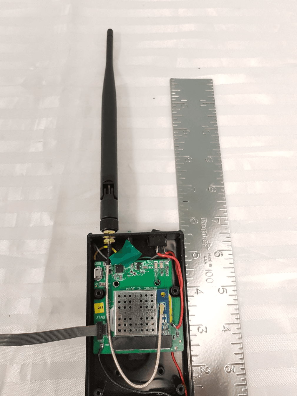
2ABFD-MDF1019
May 27, 2021Wireless transceiver module
Equipment Class
DTS - Digital Transmission System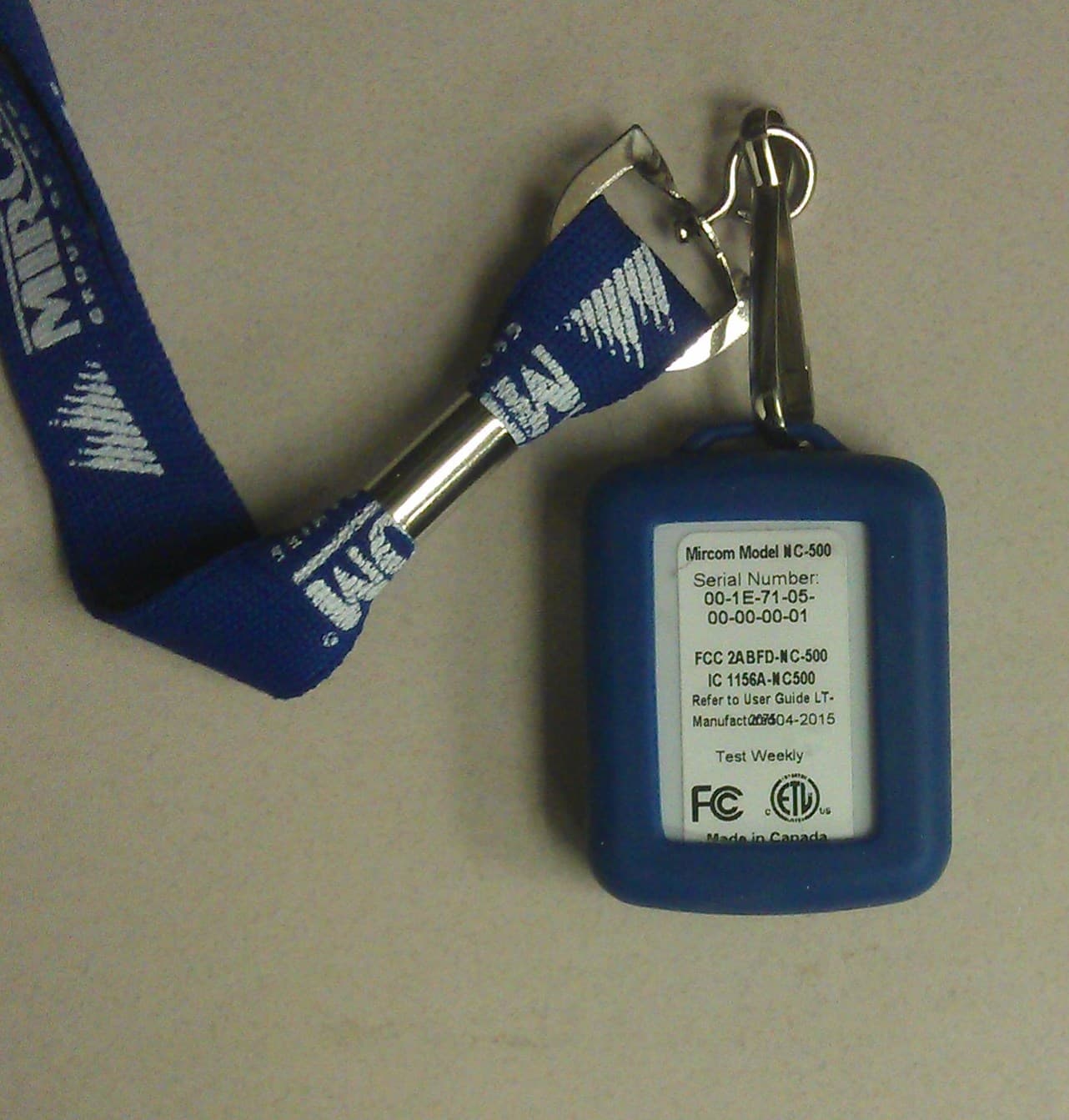
2ABFD-NC-500
Nov 09, 2015NC-500 MiCare Pendant
Equipment Class
DTS - Digital Transmission System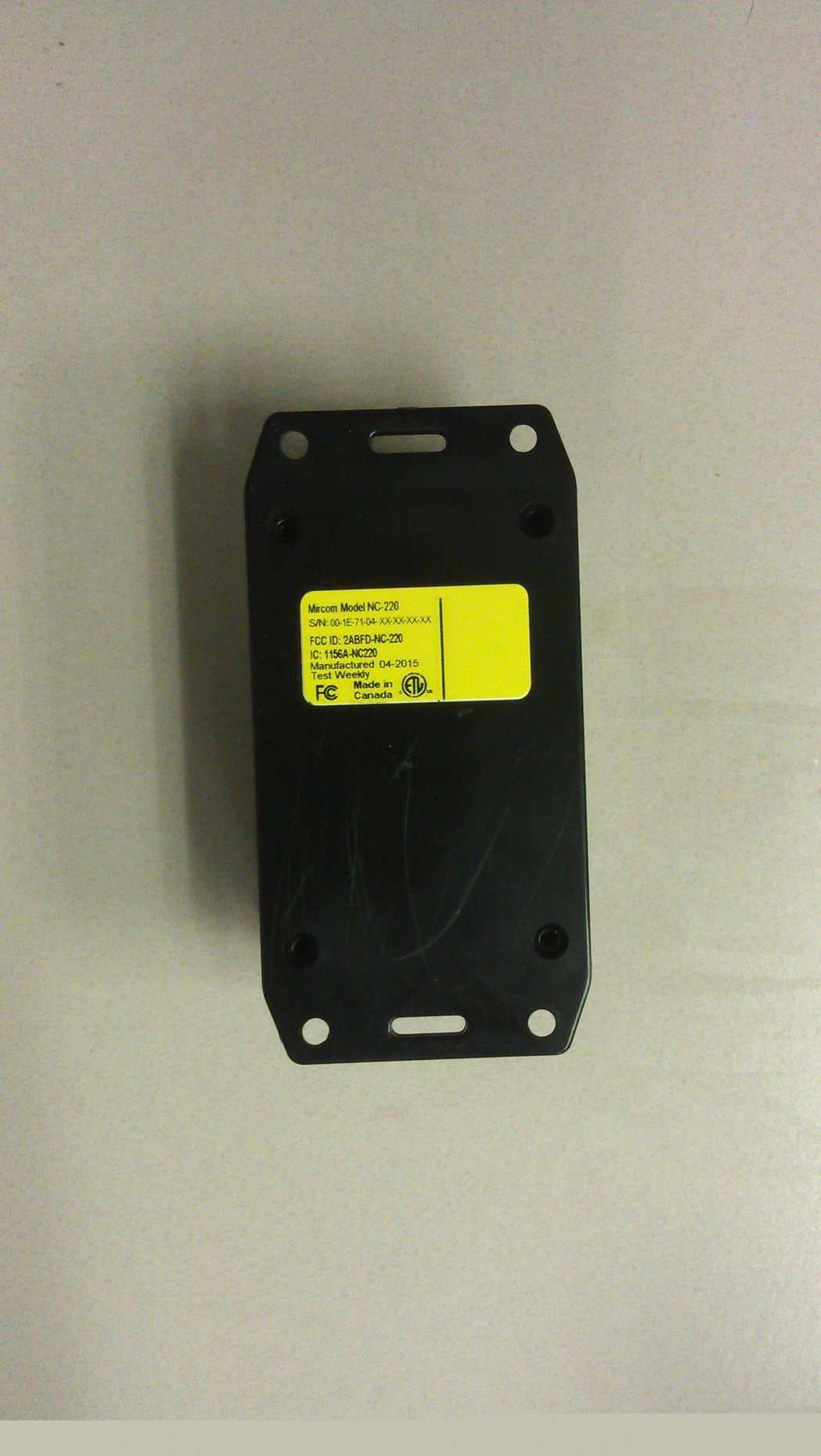
2ABFD-NC-220
Nov 09, 2015NC-220 MiCare ZF3
Equipment Class
DTS - Digital Transmission System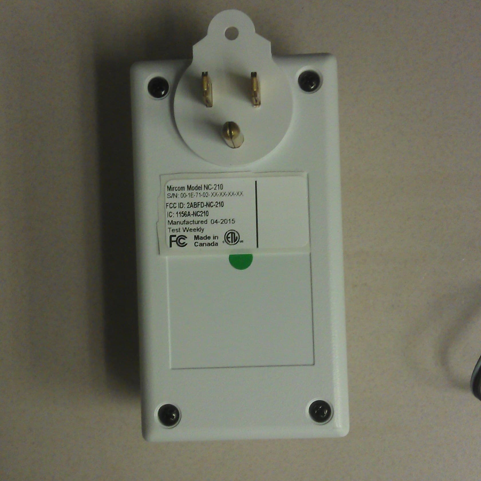
2ABFD-NC-210
Nov 09, 2015NC-210 MiCare Beacon
Equipment Class
DTS - Digital Transmission System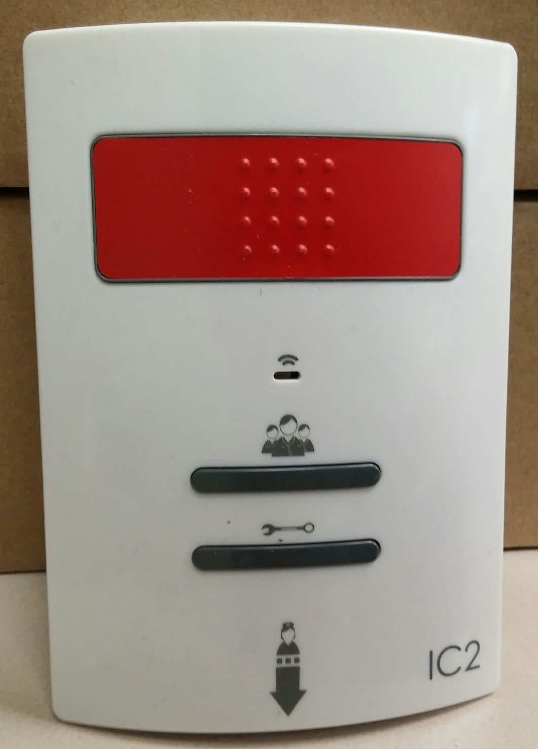
2ABFD-NC-103
Nov 08, 2015NC-103 MiCare Pull Station
Equipment Class
DTS - Digital Transmission System