2ABFHVT-9512TXWireless Camera Panner
VIDEOTEK COMPANY LIMITED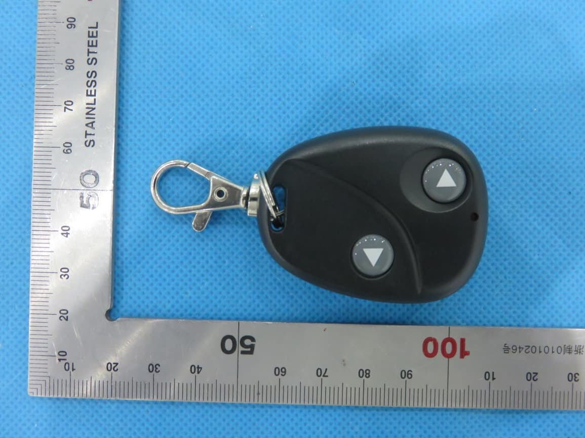
Click to zoom
Application Details
- Equipment Class
- DXX - Part 15 Low Power Communication Device Transmitter
- Date of Grant
- Jul 25, 2015
- Application Purpose
- Original Equipment
- Date of Application
- Jul 25, 2015
- Equipment Note
- Wireless Camera Panner
- Frequency Range
- 315.00000000 - 315.00000000
- Company
- VIDEOTEK COMPANY LIMITED
- Country
- China
Documents & Files
Document Text
Text extracted from the exhibit documents filed with the FCC. Open a document above to read the original.
Users Manual
Wireless PannerOperating Instructions Wireless Panner Specs 1. Distance:Up to 10 meters 2. Charging power: 5V/500mA 3. Power consumption: 0.2W 4. Battery: 3.7V/2200mA 5. Remote battery FCC ID:2ABFHVT-9512RX VT-9512RX Diagram of features: A: Power button [on panner] B: LED light [on panner] C: Left control button: pans to the left [on remote] D: Right control button: pans to the right [on remote] E: Charging port [on panner] Operation : Deploy the camera: Lower your camera to the desired depth, then position the cable in the u-shaped channel on the bottom of the panner. Use the retainer clip to anchor the camera cable in place. Open the legs of the panner and position it above the hole in the ice. Turn on and operate the panner: Press and hold the power button (A) about 3-4 secondsuntil the light is on. Press the C or D button to pan left or right. Turn off the panner: Press and hold the power button (A) for about 3-4 secondsuntil the light is off. FCC ID:2ABFHVT-9512TX VT-9512TX TROUBLE SHOOTING: 1. Pairing: Turn on the wireless panner, and quickly press the power button (A) 3 times in 3 seconds. Next, pressand hold either button(C or D) on the remoteuntilthe motor is rotating to left or right. This means that the pairing is OK,and the wireless panner can be controlled by this remote. 2. Using a new remote: If the remote is lost, you first must order a new remote. Once you have a new remote: Step 1: Turn on the wireless panner, and quickly press the power button (A) 6 times in 6 seconds, the LED light will turn off automatically in 10 seconds. Step 2: Turn the wireless panner back on and quickly press the power button (A) 3 times in 3 seconds; Step 3: Press and hold either button(C or D) of the new remoteuntil the motor is rotating to left or right. This means that thepairing is OK, and the wireless panner can be controlled by this remote. 3. Charging instruction: 1. When the panner is charging, the LED light will be pulsing slowly. 2. When it hasfully charged, the LED light will stop pulsing andalwaysbe on. 3. If the charger is disconnected during the charging process, the panner will be turned offautomatically. 4. When the panner is working, a steadyLED light means a fully charged battery. If the light is flickering in a pattern, the number of flickers indicates the battery strength out of a possible 4 levels. [Example: the light flickering in a repeating pattern of 2 indicates battery strength is 2 out of 4. 5. The LED lightflickeringvery quickly indicates the battery does not have sufficient power. N OTE : This equipment has been tested and found to comply with the limits for a Class B digital device, pursuant to part 15 of the FCC Rules. These limits are designed to provide reasonable protection against harmful interference in a residential installation. This equipment generates, uses and can radiate radio frequency energy and, if not installed and used in accordance with the instructions, may cause harmful interference to radio communications. However, there is no guarantee that interference will not occur in a particular installation. If this equipment does cause harmful interference to radio or television reception, which can be determined by turning the equipment off and on, the user is encouraged to try to correct the interference by one or more of the following measures: —Reorient or relocate the receiving antenna. —Increase the separation between the equipment and receiver. —Connect the equipment into an outlet on a circuit different from that to which the receiver is connected. —Consult the dealer or an experienced radio/TV technician for help. This device complies with part 15 of the FCC rules. Operation is subject to the following two conditions: (1) this device may not cause harmful interference, and (2) this device must accept any interference received, including interference that may cause undesired operation. Changes or modifications to this unit not expressly approved by the party responsible for compliance could void the user's authority to operate the equipment. The device meets RF Exposure requirements without any restriction.
Attestation Statements
VIDEOTEK COMPANY LIMITED Bldg 12, Section B, BaoSheng Industrial Area, BaiNikeng, PingHu Town,shenzhen,china TEL: 0755-33826808 FAX: 0755-82977631 Jul.22, 2015 TUV SUD BABT TCB Octagon House, Segensworth Road, Fareham, Hampshire, PO15 5RL Subject: Explanation of differences between product types FCC ID : 2ABFHVT-9512TX Model Number: VT-9512TX, 857224002651 To Whom It May Concern: We, VIDEOTEK COMPANY LIMITED, hereby declare that the model : 857224002651 is identical with the model : VT-9512TX, except the model name. Except for the different above, no other modification is performed. Sincerely, VIDEOTEK COMPANY LIMITED Signature: Company Officer: Zou Yu Lan Telephone Number: 0755-33826808 Email: [email protected]
Cover Letter(s)
VIDEOTEK COMPANY LIMITED Bldg 12, Section B, BaoSheng Industrial Area, BaiNikeng, PingHu Town,shenzhen,china TEL: 0755-33826808 FAX: 0755-82977631 Date (20/07/2015) TUV SUD BABT TCB Octagon House, Segensworth Road, Fareham, Hampshire, PO15 5RL Confidentiality Request FCC ID: 2ABFHVT-9512TX Pursuant to Sections 0.457(d)(1)(ii) and 0.459 of the Commission’s Rules, VIDEOTEK COMPANY LIMITED hereby requests permanent confidential treatment of information accompanying this application as outlined below: 1.Schematics 2.Bill of Materials/Parts List 3.Block Diagrams 4.Theory of Operation The above materials contain trade secrets and proprietary information not customarily released to the public. The public disclosure of these matters might be harmful to the Applicant and provide unjustified benefits to its competitors. The Applicant understands that pursuant to Rule 0.457(d)(1)(ii), disclosure of this Application and all accompanying materials will not be made before the date of the Grant for this Application. Yours sincerely, Company Officer: Zou Yu Lan Telephone Number: 0755-33826808 Email: [email protected]
External Photos
External Photos TOP VIEW OF EUT BOTTOM VIEW OF EUT FRONT VIEW OF EUT BACK VIEW OF EUT LEFT VIEW OF EUT RIGHT VIEW OF EUT
ID Label/Location Info
FCC ID Label Location wireless camera panner Model: VT-9512TX FCC ID: 2ABFHVT-9512TX wireless camera panner Model: VT-9512TX FCC ID: 2ABFHVT-9512TX
Internal Photos
Internal Photos OPEN VIEW OF EUT INTERNAL VIEW OF EUT-1 INTERNAL VIEW OF EUT-2
RF Exposure Info
RF Exposure evaluation Product Description: wireless camera panner Model Number: VT-9512TX FCC ID: 2ABFHVT-9512TX According to 447498 D01 General RF Exposure Guidance v05 The 1-g and 10-g SAR test exclusion thresholds for 100 MHz to 6 GHz at test separation distances ≤ 50 mm are determined by: [(max. power of channel, including tune-up tolerance, mW)/(min. test separation distance, mm)] ·[√f(GHz)] ≤ 3.0 for 1-g SAR and ≤ 7.5 for 10-g extremity SAR, where f(GHz) is the RF channel transmit frequency in GHz Power and distance are rounded to the nearest mW and mm before calculation According to the follow transmitter output power(P t )formula: P t =(E x d) 2 /(30 x g t ) P t =transmitter output power in watts g t =numeric gain of the transmitting antenna (unitess) E=electric field strength in V/m d=measurement distance in meters (m) According to the above test data, Emax=40.61 dBuv/m=0.000107V/m,d=3m,g t =0.3 P t =(E x d) 2 /(30 x g t )=(0.000107x3) 2 /(30x0.3)=1.21x10 -8 W=1.21x10 -5 mW The result is rounded to one decimal place for comparison Worse case is as below: [315MHz -1.21x10 -5 mW output power] (1.21x10 -5 mW /5mm) .[√0.315(GHz)]= 1.36x10 -6 <3.0 for 1-g SAR Then SAR evaluation is not required NOTE: For the maximum power, you can refer FCC test report.
Test Report
FCC ID APPLI PROD U BRAND MODE CLIEN DATE O STAND REPOR A CAUTIO This rep laborato D CATION P U UCT DESIG D NAME EL NAME T OF ISSUE DARD(S) RT VERSIO Attestat ON: port shall n ory and sha FC Rep URPOSE GNATION ON tion of G not be repro all not be q C Te port No.: : 2ABF : Origi : wirel : : VT‐9 : VIDE : Jun.2 : FCC P : V1.0 Global C oduced exc quoted out o est R AGC0176 FHVT‐9512 inal Equipm less camer 9512TX, 85 EOTEK COM 25, 2015 Part 15 Rul Complia cept in full w of context. Rep 65150501 2TX ment a panner 722400265 MPANY LIM les ance (Sh without the port 1FE03 51 MITED henzhen e written p t n) Co., L permission Page 1 Ltd of the test of 27 AGC01765150501FE03 Page 2 of 27 Report Revise Record Report Version Revise Time Issued Date Valid VersionNotes V1.0 / Jun.25, 2015Valid Original Report AGC01765150501FE03 Page 3 of 27 TABLE OF CONTENTS 1. VERIFICATION OF CONFORMITY ............................................................................................................ 4 2. GENERAL INFORMATION ........................................................................................................................ 5 2.1. PRODUCT DESCRIPTION ................................................................................................................. 5 2.2. RELATED SUBMITTAL(S) / GRANT (S) ............................................................................................. 5 2.3. TEST METHODOLOGY ...................................................................................................................... 5 2.4. SPECIAL ACCESSORIES .................................................................................................................. 5 2.5. EQUIPMENT MODIFICATIONS .......................................................................................................... 5 3. MEASUREMENT UNCERTAINTY ............................................................................................................. 6 4. DESCRIPTION OF TEST MODES ............................................................................................................. 6 5. SYSTEM TEST CONFIGURATION ............................................................................................................ 6 5.1. EQUIPMENT USED IN EUT SYSTEM ................................................................................................ 6 5.2. SUMMARY OF TEST RESULTS ......................................................................................................... 6 6. TEST FACILITY .......................................................................................................................................... 7 7. ANTENNA REQUIREMENT ....................................................................................................................... 7 8. PROVISION FOR MOMENTARY OPERATION ......................................................................................... 9 8.1 MEASUREMENT PROCEDURE ......................................................................................................... 9 8.2 TEST SETUP ....................................................................................................................................... 9 8.3 TEST RESULT ................................................................................................................................... 10 9. DUTY CYCLE CORRECTION FACTOR ............................................................................................... 11 9.1 MEASUREMENT PROCEDURE ........................................................................................................ 11 9.2 TEST SETUP ...................................................................................................................................... 11 9.3 TEST RESULT ............................................................................................................... .................... 12 Test Mode: EUT @ 315MHz for RF Transmitter ....................................................................................... 12 10. RADIATED EMISSION ........................................................................................................................... 15 10.1. MEASUREMENT PROCEDURE .................................................................................................... 15 10.2. TEST SETUP .................................................................................................................................. 17 10.3. TEST RESULT ................................................................................................................................ 18 11. BANDWIDTH .......................................................................................................................................... 20 11.1. MEASUREMENT PROCEDURE ..................................................................................................... 20 11.2. TEST SETUP .................................................................................................................................. 20 11.3. TEST RESULT ................................................................................................................................ 21 APPENDIX A: PHOTOGRAPHS OF TEST SETUP ..................................................................................... 22 APPENDIX B: PHOTOGRAPHS OF EUT .................................................................................................... 23 1 A A M A P B T S M D D C R W T e t h th . VERIFIC Applicant Address Manufacture Address Product Des Brand Name Test Model: Series Mode Model Differe Date of test Deviation Condition of Report Temp We hereby ce The above eq valuation, te he procedur his report is CATION OF er signation e el ence f Test Samp plate ertify that: quipment wa est procedur es given in A in complian F CONFOR VIDEO Bldg, Shen z VIDEO Bldg, Shen z wirele VT-95 85722 All the Jun.1 None …
Text truncated - open the document above for the full version.
Test Setup Photos
APPENDIX IV PHOTOGRAPHS OF TEST SETUP RADIATED EMISSION TEST SETUP
Contact Information
Applicant
Zou Yu lan(Manager)
Test Firm
Compliance Certification Services (Shenzhen) Inc.Harry Li
Technical Specifications
| # | Rule Parts | Frequency Range | Power Output |
|---|---|---|---|
| 1 | 15C | 315 MHz - 315 MHz | - |
Other Applications from VIDEOTEK COMPANY LIMITED
2ABFHVTC6110TX
Dec 14, 2015iBall Wireless Trailer Hitch Camera System
Equipment Class
DXX - Part 15 Low Power Communication Device Transmitter
2ABFHVT-9512RX
Jul 25, 2015Wireless Camera Panner
Equipment Class
CYY - Communications Receiver used w/Pt 15 Transmitter
2ABFHVDT-7108
Dec 25, 2013Underwater Camera System
Equipment Class
DTS - Digital Transmission System
2ABFHVDT-7106
Dec 25, 2013Underwater Camera System
Equipment Class
DTS - Digital Transmission System