2ABFHVTC6110TXiBall Wireless Trailer Hitch Camera System
VIDEOTEK COMPANY LIMITED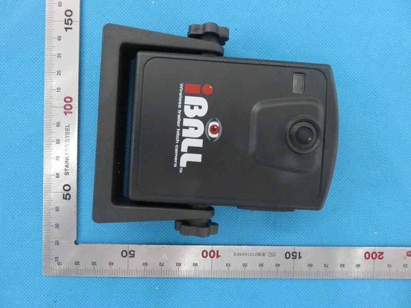
Click to zoom
Application Details
- Equipment Class
- DXX - Part 15 Low Power Communication Device Transmitter
- Date of Grant
- Dec 14, 2015
- Application Purpose
- Original Equipment
- Date of Application
- Dec 14, 2015
- Equipment Note
- iBall Wireless Trailer Hitch Camera System
- Frequency Range
- 5805.00000000 - 5805.00000000
- Company
- VIDEOTEK COMPANY LIMITED
- Country
- China
Documents & Files
Document Text
Text extracted from the exhibit documents filed with the FCC. Open a document above to read the original.
Users Manual
Outdoors Insight, Inc. www.iballhitchcam.com Call Toll Free 1-(877)-298-2055 1) Monitor 2) Select Up Down 3) Menu 4) *Picture Rotate. 5) Power 6) Fuse Cap 7) Camera 8) Adjustment Knobs 9) Power On Button 10) USB Charging Port 11) USB Charging Cable *Your model may have either of the following two buttons: or for the Picture Rotate button Warranty Information: Your iBall Wireless Camera System comes with the following warranty coverage: • 30 Day Money Back Guarantee : If you are unsatisfied for any reason, send your system back within 30 days of the original purchase date for a full refund (less shipping). • One Year Warranty: If your iBall Wireless Camera System fails due to a manufacturing defect within one year of the original purchase date, we will gladly repair or replace. 11 9 8 2 1 3 4 5 6 7 10 695 iBall manual 2016.indd 110/16/15 10:32 AM VT-C6110 • Your iBall Wireless Trailer Hitch Camera is equipped with a rechargeable lithium ion battery. Before first use, charge the camera for 8 hours. During periods of limited usage, charge the unit for 8 hours every 30 days to obtain peak battery performance. To charge, simply lift side tab and insert supplied USB charger. A solid red light will indicate the unit is charging. • To Power on the Camera, press and hold for five seconds. A red light on the front of the camera will indicate the system is on. Place the camera on any magnetic surface. Use the side adjustment knobs to adjust the viewing angle. • Plug the monitor into any 12v auxiliary port. Press the to turn on/ off the monitor. The monitor settings can be adjusted for brightness, contrast and saturation by pressing the menu button. Use the ▲ ▼ arrows to adjust the desired settings. The camera orientation can be adjusted by pressing the picture rotate button (#4). SPECIFICATIONS: Camera 5.8GHz Wireless Frequency 100’ Transmission Distance (without obstruction) Weather Resistant Lithium Ion Rechargeable Battery (charge using supplied USB cable) Magnetic Mounting 120° Field of View Monitor 3.5” Color LCD Monitor Weather Resistant 12v Auxiliary Power Supply 6” Adjustable Gooseneck HOW TO USE Helpful tips: • It is not recommended to leave the camera attached to your vehicle while traveling at high speeds, as road vibration may cause the magnetic bond to fail. • While the camera is weather resistant, it is not recommended to submerse for an extended period of time. For additional technical support, please visit our website: www.iballhitchcam.com or call us at (877)-298-2055 PROBLEM: CAUSE:SOLUTION: Poor image quality/ static Cause 1: Distance between camera and monitor too far Cause 2: Environmental interference Cause 3: Low camera battery, weak 12v monitor connection Solution 1: Move the camera closer to the monitor Solution 2: Move away from buildings or objects that may be affecting wireless signal Solution 3: Charge the camera battery, check 12v connection Problem: Camera will not turn on/off Cause 1: Power button not being held down long enough Cause 2: Low camera battery Solution 1: Firmly hold power button for at least five seconds Solution 2: Charge camera for eight hours Problem: Monitor will not turn on Cause 1: 12v outlet is not supplying power Cause 2: 12v connection is not secure Cause 3: Blown fuse in monitor 12v power plug Solution 1: Try another 12v outlet Solution 2: Firmly secure the power plug into the outlet Solution 3: Replace the fuse (3A 250v) by turning the fuse cap (#6) counterclockwise Problem: Camera will not stick to vehicle Cause 1: Non-ferrous surface Solution 1: Mount camera to iron surface, such as the receiver hitch P O W E R 695 iBall manual 2016.indd 210/16/15 10:32 AM NOTE: This equipment has been tested and found to comply with the limits for a Class B digital device, pursuant to part 15 of the FCC Rules. These limits are designed to provide reasonable protection against harmful interference in a residential installation. This equipment generates uses and can radiate radio frequency energy and, if not installed and used in accordance with the instructions, may cause harmful interference to radio communications. However, there is no guarantee that interference will not occur in a particular installation. If this equipment does cause harmful interference to radio or television reception, which can be determined by turning the equipment off and on, the user is encouraged to try to correct the interference by one or more of the following measures: - Reorient or relocate the receiving antenna. - Increase the separation between the equipment and receiver. -Connect the equipment into an outlet on a circuit different from that to which the receiver is connected. -Consult the dealer or an experienced radio/TV technician for help Changes or modifications not expressly approved by the party responsible for compliance could void the user's authority to operate the equipment. This device complies with Part 15 of the FCC Rules. Operation is subject to the following two conditions: (1) this device may not cause harmful interference, and (2) this device must accept any interference received, including interference that may cause undesired operation.
Attestation Statements
Federal Communications Commission Authorization and Evaluation Division Equipment Authorization Branch 7435 Oakland Mills Road Columbia, MD 21046 12/8/2015 To whom it may concern: We, the undersigned, hereby authorize Eurofins Product Service GmbH to act on our behalf in all matters relating to applications for equipment authorization FCC ID: 2ABFHVTC6110TX including the signing of all documents related to these matters. Any and all acts carried out by Eurofins Product Service GmbH on our behalf shall have the same effect as acts of our own. We also hereby certify that no party to this application is subject to a denial of benefits, including FCC benefits, pursuant to Section 5301 of the Anti-Drug Abuse Act of 1988, 21 U.S.C. 862. Sincerely, Signature Company Officer: Zou Yu lan Company address: Bldg, 12, Section B, Baosheng Industrial Area, Bainikeng, Pinghu town, Shenzhen, CN Email: [email protected]
Cover Letter(s)
Federal Communications Commission Equipment Authorization Branch 7435 Oakland Mills Road Columbia, MD 21046 12/8/2015 Request for Confidentiality Company name: VIDEOTEK COMPANY LIMITED FCC ID: 2ABFHVTC6110TX FCC Part 15 Certification Gentlemen, In accordance with CFR 47 § 0.459, VIDEOTEK COMPANY LIMITED hereby requests confidentiality of following attachments: (1) schematic diagrams, (2) parts lists. (3)block diagrams (4)operational description These documents contain detailed system and equipment description and related information about the product which VIDEOTEK COMPANY LIMITED considers to be proprietary, confidential and a custom design and otherwise would not release to the general public. Since the design is a basis from which future technological products will evolve, VIDEOTEK COMPANY LIMITED considers that this information would be of benefit to its competitors and that the disclosure of the information in these documents would give competitors an unfair advantage in the market. Sincerely, Company Officer: Zou Yu lan Company address: Bldg, 12, Section B, Baosheng Industrial Area, Bainikeng, Pinghu town, Shenzhen, CN Email: [email protected]
External Photos
External Photos TOP VIEW OF EUT BOTTOM VIEW OF EUT FRONT VIEW OF EUT BACK VIEW OF EUT LEFT VIEW OF EUT RIGHT VIEW OF EUT
ID Label/Location Info
FCC ID Label Location VT-C6110 FCC ID: 2ABFHVTC6110TX Changes or modifications not expressly approved by the party responsible for compliance could void the user's authority to operate the equipment. This device complies with Part 15 of the FCC Rules. Operation is subject to the following two conditions: (1) this device may not cause harmful interference, and (2) this device must accept any interference received, including interference that may cause undesired operation.
Internal Photos
Internal Photos OPEN VIEW OF EUT INTERNAL VIEW OF EUT-1 Antenna INTERNAL VIEW OF EUT-2 INTERNAL VIEW OF EUT-3
Operational Description
Declaration concerning Antenna Specification It is hereby declared that the product Model No.: VT-C6110, iBall-M 5.8Ghz, VT-6110 FCC ID: 2ABFHVTC6110TX fulfills the requirement in FCC test relating to the antenna type. The device specified above confirms to the FCC recommendations for PCB antenna type described below: Model No. of antenna: N/A Type of antenna: Integrated antenna permanently attached Gain of the antenna: 2.5dBi Frequency range: 5.805GHz The mounting of the antenna is fixed to the radio module and no other antenna should be used. Company name: VIDEOTEK COMPANY LIMITED Address: Bldg, 12, Section B, Baosheng Industrial Area, Bainikeng, Pinghu town, , City: Shenzhen ZIP / Postal code:518000 Country: China Place: Shenzhen Date: 2015-12-08 Signature:
RF Exposure Info
RF EXPOSURE EVALUATION 1. PRODUCT INFORMATION Product Description iBall Wireless Trailer Hitch Camera System Model Number VT-C6110, iBall-M 5.8Ghz, VT-6110 FCC ID 2ABFHVTC6110TX 2. EVALUATION METHOD According to 447498 D01 General RF Exposure Guidance v05 The 1-g and 10-g SAR test exclusion thresholds for 100 MHz to 6 GHz at test separation distances ≤ 50 mm are determined by: [(max. power of channel, including tune-up tolerance, mW)/(min. test separation distance, mm)] ·[√f(GHz)] ≤ 3.0 for 1-g SAR and ≤ 7.5 for 10-g extremity SAR. Where f(GHz) is the RF channel transmit frequency in GHz Power and distance are rounded to the nearest mW and mm before calculation 3. CALCULATION According to the follow transmitter output power(P t )formula: P t =(E x d) 2 /(30 x g t ) P t =transmitter output power in watts g t =numeric gain of the transmitting antenna (unitess) E=electric field strength in V/m d=measurement distance in meters (m) According to the report AGC01765151101FE03, E max =88.28dBuv/m=0.026V/m, d=3m,g t =1.78 P t =(E x d) 2 /(30 x g t )=(0.026x3) 2 /(30x1.78)=0.000114W=0.114mW The result for RF exposure evaluation SAR=(0.114mW /5mm) .[√5.805(GHz)]= 0.055<3.0 for 1-g SAR 4. CONCLUSION The SAR evaluation is not required.
Test Report
Page 1 of 34 FCC Test Report Report No.: AGC01765151101FE03 FCC ID : 2ABFHVTC6110TX APPLICATION PURPOSE : Original Equipment PRODUCT DESIGNATION : iBall Wireless Trailer Hitch Camera System BRAND NAME : iBall Wireless Trailer Hitch Camera / VDT MODEL NAME : VT-C6110, iBall-M 5.8Ghz, VT-6110 CLIENT : VIDEOTEK COMPANY LIMITED DATE OF ISSUE : Nov.30, 2015 STANDARD(S) TEST PROCEDURE(S) : FCC Part 15 Rules REPORT VERSION : V1.0 Attestation of Global Compliance (Shenzhen) Co., Ltd CAUTION: This report shall not be reproduced except in full without the written permission of the test laboratory and shall not be quoted out of context. Report No.: AGC01765151101FE03 Page 2 of 34 Report Revise Record Report Version Revise Time Issued Date Valid Version Notes V1.0 / Nov.30, 2015 Valid Original Report Report No.: AGC01765151101FE03 Page 3 of 34 TABLE OF CONTENTS 1. VERIFICATION OF CONFORMITY ............................................................................................................ 4 2. GENERAL INFORMATION ........................................................................................................................ 5 2.1. PRODUCT DESCRIPTION ................................................................................................................. 5 3. MEASUREMENT UNCERTAINTY ............................................................................................................. 6 4. DESCRIPTION OF TEST MODES ............................................................................................................. 6 5. SYSTEM TEST CONFIGURATION ............................................................................................................ 7 5.1. CONFIGURATION OF EUT SYSTEM ................................................................................................. 7 5.2. EQUIPMENT USED IN EUT SYSTEM ................................................................................................ 7 5.3. SUMMARY OF TEST RESULTS ......................................................................................................... 7 6. TEST FACILITY .......................................................................................................................................... 8 7. RADIATED EMISSION ............................................................................................................................... 9 7.1TEST LIMIT ........................................................................................................................................... 9 7.2. MEASUREMENT PROCEDURE ...................................................................................................... 10 7.3. TEST SETUP .................................................................................................................................... 12 7.4. TEST RESULT .................................................................................................................................. 14 8. BAND EDGE EMISSION .......................................................................................................................... 17 8.1. MEASUREMENT PROCEDURE ...................................................................................................... 17 8.2 TEST SETUP ..................................................................................................................................... 17 8.3 RADIATED TEST RESULT ................................................................................................................ 18 9. 20DB BANDWIDTH .................................................................................................................................. 22 9.1. MEASUREMENT PROCEDURE ...................................................................................................... 22 9.2. TEST SET-UP (BLOCK DIAGRAM OF CONFIGURATION) ............................................................. 22 9.3. MEASUREMENT RESULTS ............................................................................................................. 22 10. LINE CONDUCTED EMISSION TEST ................................................................................................... 24 10.1. LIMITS OF LINE CONDUCTED EMISSION TEST ......................................................................... 24 10.2. BLOCK DIAGRAM OF LINE CONDUCTED EMISSION TEST ....................................................... 24 10.3. PRELIMINARY PROCEDURE OF LINE CONDUCTED EMISSION TEST ..................................... 25 10.4. FINAL PROCEDURE OF LINE CONDUCTED EMISSION TEST ................................................... 25 10.5. TEST RESULT OF LINE CONDUCTED EMISSION TEST ............................................................. 26 APPENDIX A: PHOTOGRAPHS OF TEST SETUP ..................................................................................... 28 APPENDIX B: PHOTOGRAPHS OF EUT .................................................................................................... 30 Report No.: AGC01765151101FE03 Page 4 of 34 1. VERIFICATION OF CONFORMITY Applicant VIDEOTEK COMPANY LIMITED Address Bldg, 12, Section B, Baosheng Industrial Area, Bainikeng, Pinghu town, Shenzhen, CN Manufacturer VIDEOTEK COMPANY LIMITED Address Bldg, 12, Section B, Baosheng Industrial Area, Bainikeng, Pinghu town, Shenzhen, CN Product Designation iBall Wireless Trailer Hitch Camera System Brand Name iBall Wireless Trailer Hitch Camera / VDT Test Model VT-C6110 Series Model iBall-M 5.8Ghz, VT-6110 Difference description All the same except for the model name. Date of test Nov.20, 2015 to Nov.24, 2015 Deviation None Condition of Test Sample Normal Report Template AGCRT-US-BR/RF We hereby certify that: The above equipment was tested by Dongguan Precise Testing Service Co., Ltd. The test data, data evaluation, test procedures, and equipment configurations shown in this report were made in accordance with th…
Text truncated - open the document above for the full version.
Test Setup Photos
Test Setup Photos RADIATED EMISSION TEST SETUP BELOW 1GHz RADIATED EMISSION TEST SETUP ABOVE 1GHz CONDUCTED EMISSION TEST SETUP
Contact Information
Applicant
Zou Yu lan(Manager)
Test Firm
Dongguan Precise Testing Service Co., Ltd.Chris Du
Technical Specifications
| # | Rule Parts | Frequency Range | Power Output |
|---|---|---|---|
| 1 | 15C | 5.80 GHz - 5.80 GHz | - |
Other Applications from VIDEOTEK COMPANY LIMITED

2ABFHVT-9512RX
Jul 25, 2015Wireless Camera Panner
Equipment Class
CYY - Communications Receiver used w/Pt 15 Transmitter
2ABFHVT-9512TX
Jul 25, 2015Wireless Camera Panner
Equipment Class
DXX - Part 15 Low Power Communication Device Transmitter
2ABFHVDT-7108
Dec 25, 2013Underwater Camera System
Equipment Class
DTS - Digital Transmission System
2ABFHVDT-7106
Dec 25, 2013Underwater Camera System
Equipment Class
DTS - Digital Transmission System