2ABGL-0096V Luxury Chevy Colorado Camo
Pacific Cycle, Inc.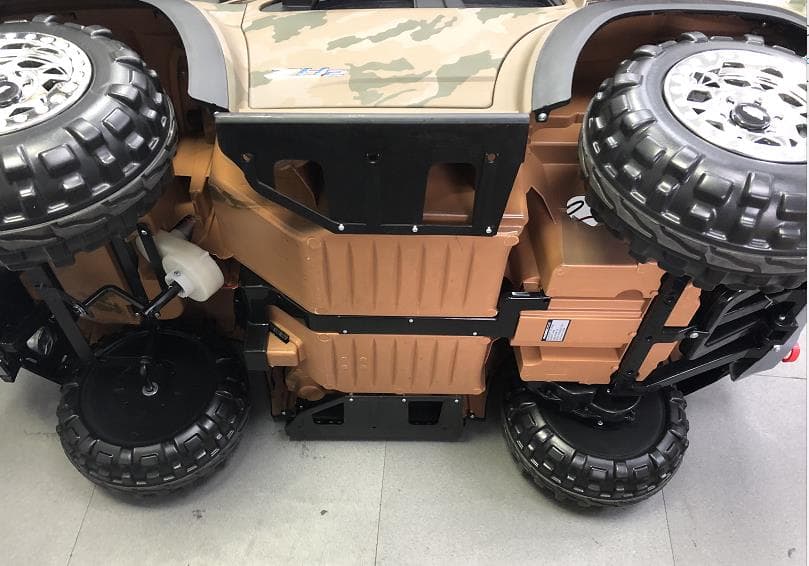
Click to zoom
Application Details
- Equipment Class
- DSS - Part 15 Spread Spectrum Transmitter
- Date of Grant
- Feb 22, 2020
- Application Purpose
- Original Equipment
- Date of Application
- Feb 21, 2020
- Equipment Note
- 6V Luxury Chevy Colorado Camo
- Frequency Range
- 2402.00000000 - 2480.00000000
- Company
- Pacific Cycle, Inc.
- Country
- United States
Documents & Files
Document Text
Text extracted from the exhibit documents filed with the FCC. Open a document above to read the original.
Users Manual
t WARNING This manual contains important safety and use information. Keep this manual for future reference. • An adult must read this entire manual • Adult supervision is required at all times Age: 3–5 years Weight: Maximum 60 lbs (27 kg) Maximum Speed: 2.5 MPH Battery: 6 volt Owner's Manual KT1545I Colorado Styles and colors may vary. Made in China CHEVROLET COLORADO ZH2, all related Emblems, and vehicle body designs are General Motors Trademarks used under license to Pinghu Weikesi Children Toys Co., Ltd. WARNINGWARNING WARNING -- -- WARNING CAUTION FAILURE TO FOLLOW THE SAFETY INSTRUCTIONS LISTED BELOW MAY RESULT IN SERIOUS INJURY OR DEATH. The owner’s manual contains assembly, use and maintenance instructions. Safe Riding Warnings • Not be used by children under three (3) years of age or children over five (5) years of age • Do not exceed the maximum weight capacity of 60 lbs. (27kg) • Do not allow more than one (1) rider. ADULTS AND SUPERVISORS, PLEASE NOTE: 1. Always instruct all children of common sense rules and safe practices. 2. Be aware that flat, hard surfaces provide the safest experience for child riders. 3. Do not allow the child rider to operate the ride-on toy near streets, roads, sidewalks, walkways, or any other place where they may encounter other moving vehicles. 4. Never leave children unattended with this ride-on toy. Continuous adult supervision is required. 5. If necessary, adults and supervisors are always responsible for setting up gates and barriers to ensure a safe riding environment for the child rider. 6. Be aware that this ride-on toy does not have braking capabilities. Allowing use of this ride-on toy in areas that require braking may cause rolls, crashes, serious injury, or death to the child rider. 7. Teach children not to allow other children to use this ride-on toy. Communicate this message to other adults and supervisors of fellow children with which your child interacts. 8. Sternly alert children that hands, legs, hair, and clothing can potentially get caught in moving parts. Ensure they never place a body part or piece of clothing near a moving part of the ride-on toy. Avoid loose clothing. • Battery posts, terminals and related accessories contain lead and lead compounds (acids) chemicals and are toxic and corrosive. Never open the battery. • Contact or exposure to battery leakage (lead acid) may cause serious injury. If contact or exposure occurs with the skin or in the eyes, or if the chemical is swallowed, immediately call 911. • Use of a battery or charger other than the supplied rechargeable battery and charger may cause a fire or explosion. Only use the supplied rechargeable battery and charger with the ride-on toy. • Do not charge the battery near heat or flammable materials. • Using the rechargeable battery and charger for any other product many result in overheating, fire or explosion. Never use the rechargeable battery and charger with another product. Re-Charge Interval and Time Important! • Damage to the battery may occur if it is allowed to drain completely. Do not allow the battery to drain completely. • Check the battery and charger (supply cord, connector) for wear and damage before charging. Do not charge the battery if damage has occurred. Do not use an extension cord when charging the ride-on toy. • On average you will need to charge the battery for 10 hours and no more than 24 hours. Failure to charge the battery as directed could cause permanent damage to the battery and void the warranty. • Only an adult who has read and understands the safety warnings should handle, charge and recharge the battery. Child Safety Warnings • Adults supervising children must read and understand this entire manual before allowing any child to use this product. • Adults must evaluate their own children as to maturity, strength, judgment and ability to follow safety rules. Published age guidelines are not a substitute for careful evaluation of your own child. • Adults must teach children about thinking ahead while riding as this may be the first time a child has ever controlled a motorized ride-on toy. While you supervise, see through the child’s eyes, and verbally teach them about steering and avoiding obstacles in the approved riding area. 9. Instruct children to always wear shoes when using the ride-on toy. 10. Confirm that children do not have access to the charging equipment or come into contact with any part of the ride-on toy while it is charging. 11. Do not mix old and new batteries. 12. Do not mix alkaline, standard (carbon zinc), or rechargeable batteries. 13. Firmly instruct children to use the ride-on toy in a safe manner. Unsafe behaviors include, but are not limited to: • Traveling at unsafe speeds • Not riding in the seated position • Riding at night or in any conditions of low visibility • Riding in any wet conditions including rain, snow, and ice • Any kind of stunt riding: jumps, ramps, stairs, hills, sloped surfaces, or other actions involving any notable risk • Any kind of off-road riding: rough terrain, dirt, mud, gravel, or any others that involve notable risk • Riding near any pool or open body of water • Pushing, pulling, or shoving the driver in any way while operating the ride-on toy • Using the ride-on toy without the battery cover or any other safety cover fully closed • Pulling or hitching the ride-on toy with other similar moving ride-on toys or products • Riding a motorized ride-on toy can be a dangerous activity, even under the best of circumstances. Good choices regarding where and when to ride, constant adult supervision of riding, and practice and careful riding by the child can all help to minimize risk. However this ride-on toy is intended to move and therefore it is possible for the rider to lose control, fall off and/or get into dangerous situations that no amount of care, instruction or expertise can eliminate. • If this inherent risk is not acceptable, adults should not allow children to ride this ride-on to…
Text truncated - open the document above for the full version.
Users Manual
67 Assembly Foll ow the assembly steps in the order listed below. ❶ Ensure the gearbox i s completely i nserted into the opening in the wheel well. ❷ rear wheel ass embly to the rear axle. ❸ front wheel ass embly to the front axle. ❹ Insert the steering wheel over the end of the steering column. Fasten with the nut and bolt. Note: Connect the wire connector from the steering wheel to the wires connector coming from steering column. ❺ Place each mirror on the mirror bra cket, mirror are aligned. Fasten the mirror to the bra cket using the small cap screw. ❻ Before ❼ Fasten the seat to the body using the two ❽ charge ❷ ❷ ❸ ❸ ❺ ❺ ❶ Inse rt the hubcap tabs into the 4 slots on the wheel inset. wrench on each wheel bolt and simult aneously turn the wrenches ❼ ❹ Remove the nut and bolt from the steeri ng wheel BEFORE performing Step 4.
Users Manual
89 NOTI CE • serious injury or death if handled, connected, or charged improperl y. Only an adult who has read and understands the • 24 hours. Always disconnect the product from the charger disconnect the charger from the wall. • A damaged supply cord, connector , or charger could cause property damage. Always inspect the supply cord, connector , and charger for damage. (e.g., frayed or ki nked wires, exposed use the supply cord, connector or charger for any purp ose and properl y dispose. • using an extension cord. Always plug the charger directly into a wall outlet. • • • WARNING 18 24+ Charge Times 10 First charge Regular charge No mor e than Use ❷ ❸ ❹ The product will not turn on while plugged into the charger. Remove from charger prior to turn ing on. ❶ ❶ ❷
Users Manual
USB TF MP3 MP3 TF_CARD USB Prev/-Next/+Pause/PlayMode 88:88 Pairing the remote control to the ride-onInsert the batteries • DO NOT mix old and new batteries. • DO NOT mix alkaline, standard (carbon-zinc), or rechargeable (nickel-cadmium) batteries. • Non-rechargeable batteries are not to be recharged. Batteries are to be inserted with the correct polarity. Exhausted batteries are to be removed from the toy. The supply terminals are not to be short-circuited. Rechargeable batteries are only to be charged under adult supervision. • Rechargeable batteries are to be removed from the toy before being charged. MP3 TF_CARD USB Prev/-Next/+Pause/PlayMode 1011 Controls and Functions Remote Control Use and Functions WARNING On/Off Switch Forward/Reverse switch Press the left button to turn left, press the right button to turn right. Stop button Car select Indicator Speed indicator Press the up button to move forward, press the bottom button to move in reverse Horn Horn MP3 Player with FM Bluetooth Handle Press the pedal to accelerate Maximum Speed: 2.5 MPH Lift foot off pedal to stop ❶ The speed indicators will flash 3 times when the batteries are installed. ❷ Press the Car Select indicator for approximately 2 seconds. The Car Select indicator will flash. ❸ Press the On/Off switch on the car immediately. If the Car Select indicator is not illuminated, repeat step 2. ❶ Remove the small screw from the battery compartment cover. ❷ Lift the battery cover off the remote control. ❸ Insert two AAA-size batteries into the battery compartment as shown. Note: Batteries NOT included. ❹ Replace the battery compartment cover and fasten with the small screw you removed in step one. ❷ ❸ ❶ ❶❷ ❸
Cover Letter(s)
Request for Confidentiality Date: January 20, 2020 Subject: Confidentiality Request for: ______( FCC ID: 2ABGL-009)_____ Pursuant to FCC 47 CFR 0.457(d) and 0.459 and IC RSP-100, Section 12.4, the applicant requests that a part of the subject FCC application be held confidential. Type of Confidentiality Requested Exhibit ☐ Short Term ☒ Permanent Block Diagrams ☐ Short Term External Photos ☐ Short Term ☐ Permanent * 1 Internal Photos ☐ Short Term ☒ Permanent Operation Description/Theory of Operation ☐ Short Term ☐ Permanent Parts List & Placement/BOM ☐ Short Term ☐ Permanent Tune-Up Procedure ☐ Short Term ☒ Permanent Schematics ☐ Short Term Test Setup Photos ☐ Short Term ☐ Permanent * 3 User’s Manual ______ Pacific Cycle Inc.______ has spent substantial effort in developing this product and it is one of the first of its kind in industry. Having the subject information easily available to "competition" would negate the advantage they have achieved by developing this product. Not protecting the details of the design will result in financial hardship. Permanent Confidentiality: The applicant requests the exhibits listed above as permanently confidential be permanently withheld from public review due to materials that contain trade secrets and proprietary information not customarily released to the public. Short-Term Confidentiality: The applicant requests the exhibits selected above as short term confidential be withheld from public view for a period of ___(specify number of days not to exceed 180) 2 ___ days from the date of the Grant of Equipment Authorization and prior to marketing. This is to avoid premature release of sensitive information prior to marketing or release of the product to the public. Applicant is also aware that they are responsible to notify ACB in the event information regarding the product or the product is made available to the public before the requested period has expired. ACB will then release the documents listed above for public disclosure pursuant to FCC Public Notice DA 04-1705. NOTE for Industry Canada Applications: IC currently only distinguishes Permanent Confidentiality exhibits as shown above. Short Term confidentiality is not considered applicable to IC applications. Sincerely, By: _Ryan_Shiroma/ Sr.Quality Manager (Signature/Title 3 ) (Print name/Title) 1 - The asterisked items (*) require further information to be provided to ACB before permanent confidentiality will be extended to these exhibits. Please refer to FCC KDB 726920 and the specific Document link for D01 found at: https://apps.fcc.gov/oetcf/kdb/forms/FTSSearchResultPage.cfm?switch=P&id=41731 and review section II, 3) regarding specific information that must accompany these requests. 2 - Please refer to http://acbcert.com/documents/misc-docs/Memo-Short-Term-Vs-Standard-Confidentiality.pdf for complete details. 3 - Must be signed by applicant contact given for applicant on the FCC site, or by the authorized agent if an appropriate authorized agent letter has been provided. Letters should be placed on appropriate letterhead.
External Photos
FCC ID: 2ABGL-009 External Picture FCC ID: 2ABGL-009 FCC ID: 2ABGL-009 FCC ID: 2ABGL-009 FCC ID: 2ABGL-009 FCC ID: 2ABGL-009 Bluetooth Part
ID Label/Location Info
Label & Label Location
Internal Photos
FCC ID: 2ABGL-009 Internal Picture FCC ID: 2ABGL-009 FCC ID: 2ABGL-009 FCC ID: 2ABGL-009 FCC ID: 2ABGL-009 FCC ID: 2ABGL-009 Antenna FCC ID: 2ABGL-009 FCC ID: 2ABGL-009
RF Exposure Info
Pacific Cycle Inc. MPE ASSESSMENT REPORT Report Type: FCC MPE assessment report Model: KT1545I REPORT NUMBER: 191100696SHA-002 ISSUE DATE: Jan 14, 2020 DOCUMENT CONTROL NUMBER: TTRFFCCMPE-01_V1 © 2018 Intertek Intertek Testing Services Shanghai Building No.86, 1198 Qinzhou Road (North) Caohejing Development Zone Shanghai 200233, China Telephone: 86 21 6127 8200 www.intertek.com TEST REPORT This report is for the exclusive use of Intertek's Client and is provided pursuant to the agreement between Intertek and its Client. Intertek's responsibility and liability are limited to the terms and conditions of the agreement. Intertek assumes no liability to any party, other than to the Client in accordance with the agreement, for any loss, expense or damage occasioned by the use of this report. Only the Client is authorized to permit copying or distribution of this report and then only in its entirety. Any use of the Intertek name or one of its marks for the sale or advertisement of the tested material, product or service must first be approved in writing by Intertek. The observations and test results in this report are relevant only to the sample tested. This report by itself does not imply that the material, product, or service is or has ever been under an Intertek certification program. TTRFFCCMPE-01_V1© 2018 Intertek Page 2 of 8 Report no.: 191100696SHA-002 Applicant: Pacific Cycle Inc. 4902 hammersley Road madison, WI 53711, USA Manufacturer: PINGHU WEIKESI CHILDREN TOYS CO.,LTD No.358 Yousheng Duan, Provincial Highway 01, Dushan Harbor Town, Pinghu, Zhejiang, China FCC ID: 2ABGL-009 SUMMARY: The equipment complies with the requirements according to the following standard(s) or Specification: KDB447498 D01 General RF Exposure Guidance v06 FCC Part2.1091, FCC Part2.1093 FCC Part1.1307(b) PREPARED BY: REVIEWED BY: Project Engineer Stephanie Zhang Reviewer Wakeyou Wang Report No.: 191100696SHA-002 TEST REPORT TTRFFCCMPE-01_V1© 2018 Intertek Page 3 of 8 Revision History Report No. Version Description Issued Date 191100696SHA-002 Rev. 01 Initial issue of report Jan 14, 2020 Report No.: 191100696SHA-002 TEST REPORT TTRFFCCMPE-01_V1© 2018 Intertek Page 4 of 8 1 GENERAL INFORMATION 1.1 Description of Equipment Under Test (EUT) Product name: 6V Luxury Chevy Colorado Camo Type/Model: KT1545I Description of EUT: This is a toy car with Bluetooth module. There is only one model. Rating: Battery Charger: Input 120V,0.2A,50/60Hz; output:7VDC,0.8A Category of EUT: Class B EUT type: Table top Floor standing Software Version: / Hardware Version: / Sample received date: 11/10/2019 Date of test: 11/10/2019 – 12/29/2019 1.2 Technical Specification Frequency Range: 2400MHz ~ 2483.5MHz Support Standards: Bluetooth 4.2 (BR+EDR) Type of Modulation: GFSK, π/4 DQPSK Channel Number: 79 (0 - 78) Channel Separation: 1 MHz Antenna Information: PCB Antenna, -0.58 dBi Report No.: 191100696SHA-002 TEST REPORT TTRFFCCMPE-01_V1© 2018 Intertek Page 5 of 8 1.3 Description of Test Facility Name: Intertek Testing Services Shanghai Address: Building 86, No. 1198 Qinzhou Road(North), Shanghai 200233, P.R. China Telephone: 86 21 61278200 Telefax: 86 21 54262353 The test facility is recognized, certified, or accredited by these organizations: CNAS Accreditation Lab Registration No. CNAS L0139 FCC Accredited Lab Designation Number: CN1175 IC Registration Lab Registration code No.: 2042B-1 VCCI Registration Lab Registration No.: R-4243, G-845, C-4723, T-2252 NVLAP Accreditation Lab NVLAP LAB CODE: 200849-0 A2LA Accreditation Lab Certificate Number: 3309.02 Report No.: 191100696SHA-002 TEST REPORT TTRFFCCMPE-01_V1© 2018 Intertek Page 6 of 8 2 MPE Assessment Test result: Pass 2.1 MPE Assessment Limit Mobile device exposure for standalone operations: Frequency range E-field strength (V/m) H-field strength (A/m) B-field (uT) Equivalent plane wave power density S eq (W/m 2 ) 0-1 Hz - 3,2 × 10 4 4 × 10 4 - 1-8 Hz 10 000 3,2 × 10 4 /f 2 4 × 10 4 /f 2 - 8-25 Hz 10 000 4 000/f 5 000/f - 0,025-0,8 kHz 250/f 4/f 5/f - 0,8-3 kHz 250/f 5 6,25 - 3-150 kHz 87 5 6,25 - 0,15-1 MHz 87 0,73/f 0,92/f - 1-10 MHz 87/f 1/2 0,73/f 0,92/f - 10-400 MHz 28 0,073 0,092 2 400-2 000 MHz 1,375 f 1/2 0,0037 f 1/2 0,0046 f 1/2 f/200 2-300 GHz 61 0,16 0,20 10 Mobile device exposure for simultaneous transmission operations: the sum of the MPE ratios for all simultaneously transmitting antennas incorporated in a host device is ≤ 1.0 Report No.: 191100696SHA-002 TEST REPORT TTRFFCCMPE-01_V1© 2018 Intertek Page 7 of 8 2.2 Assessment Results Power density (S) is calculated according to the formula: S = P / (4πR²) Where S = power density in mW/cm² P = Radiated transmit power in mW G = numeric gain of transmit antenna R = distance (cm) As we can see from the test report 191100696SHA-001: The maximum radiated power = -2.72dBm = 0.535mW; Here R is chosen to be 20cm, S = P / (4πR²) = 0.535/ (4 * 3.14 * 20 * 20) = 0.0001 mW/cm² < 1 mW/cm² Report No.: 191100696SHA-002 TEST REPORT TTRFFCCMPE-01_V1© 2018 Intertek Page 8 of 8 Appendix I Definition below must be outlined in the User Manual: To satisfy FCC RF exposure requirements, a separation distance of 20 cm or more should be maintained between the antenna of this device and persons during device operation. To ensure compliance, operations at closer than this distance is not recommended. ******************************************* END ************************************
Test Report
Pacific Cycle Inc. RF TEST REPORT Report Type: FCC Part 15.247 & ISED RSS-247 RF report Model: KT1545I REPORT NUMBER: 191100696SHA-001 ISSUE DATE: Jan 14, 2020 DOCUMENT CONTROL NUMBER: TTRF15.247-01_V1 © 2018 Intertek Intertek Testing Services Shanghai Building No.86, 1198 Qinzhou Road (North) Caohejing Development Zone Shanghai 200233, China Telephone: 86 21 6127 8200 www.intertek.com TEST REPORT This report is for the exclusive use of Intertek's Client and is provided pursuant to the agreement between Intertek and its Client. Intertek's responsibility and liability are limited to the terms and conditions of the agreement. Intertek assumes no liability to any party, other than to the Client in accordance with the agreement, for any loss, expense or damage occasioned by the use of this report. Only the Client is authorized to permit copying or distribution of this report and then only in its entirety. Any use of the Intertek name or one of its marks for the sale or advertisement of the tested material, product or service must first be approved in writing by Intertek. The observations and test results in this report are relevant only to the sample tested. This report by itself does not imply that the material, product, or service is or has ever been under an Intertek certification program. TTRF15.247-01_V1 © 2017 Intertek Page 2 of 55 Report no.: 191100696SHA-001 Applicant: Pacific Cycle Inc. 4902 hammersley Road madison, WI 53711,USA Manufacturer: PINGHU WEIKESI CHILDREN TOYS CO.,LTD No.358 Yousheng Duan, Provincial Highway 01, Dushan Harbor Town, Pinghu, Zhejiang, China FCC ID: 2ABGL-009 SUMMARY: The equipment complies with the requirements according to the following standard(s) or Specification: 47CFR Part 15 (2018): Radio Frequency Devices (Subpart C) ANSI C63.10 (2013): American National Standard of Procedures for Compliance Testing of Unlicensed Wireless Devices RSS-247 Issue 2 (February 2017): Digital Transmission Systems (DTSs), Frequency Hopping Systems (FHSs) and Licence-Exempt Local Area Network (LE-LAN) Devices RSS-Gen Issue 5 (April 2018): General Requirements for Compliance of Radio Apparatus PREPARED BY: REVIEWED BY: Project Engineer Stephanie Zhang Reviewer Wakeyou Wang Report No.: 191100696SHA-001 TEST REPORT TTRF15.247-01_V1 © 2018 Intertek Page 3 of 55 Content REVISION HISTORY................................................................................................................................................ 5 MEASUREMENT RESULT SUMMARY...................................................................................................................... 6 1 GENERAL INFORMATION ............................................................................................................................. 7 1.1 DESCRIPTION OF EQUIPMENT UNDER TEST (EUT) ..................................................................................................... 7 1.2 TECHNICAL SPECIFICATION .................................................................................................................................... 7 1.3 FREQUENCY HOPPING SYSTEM REQUIREMENT .......................................................................................................... 8 1.4 DESCRIPTION OF TEST FACILITY ............................................................................................................................ 10 2 TEST SPECIFICATIONS ................................................................................................................................. 11 2.1 STANDARDS OR SPECIFICATION ............................................................................................................................. 11 2.2 MODE OF OPERATION DURING THE TEST ................................................................................................................. 11 2.3 TEST SOFTWARE LIST .......................................................................................................................................... 12 2.4 TEST PERIPHERALS LIST ....................................................................................................................................... 12 2.5 TEST ENVIRONMENT CONDITION: .......................................................................................................................... 12 2.6 INSTRUMENT LIST .............................................................................................................................................. 13 2.7 MEASUREMENT UNCERTAINTY ............................................................................................................................. 14 3 20DB BANDWIDTH .................................................................................................................................... 15 3.1 LIMIT .............................................................................................................................................................. 15 3.2 MEASUREMENT PROCEDURE ............................................................................................................................... 15 3.3 TEST CONFIGURATION ........................................................................................................................................ 16 3.4 TEST RESULTS OF 20DB BANDWIDTH ..................................................................................................................... 16 4 CARRIER FREQUENCY SEPARATION ............................................................................................................ 17 4.1 LIMIT .............................................................................................................................................................. 17 4.2 TEST CONFIGURATION ........................................................................................................................................ 17 4.3 TEST PROCEDURE AND TEST SETUP ...…
Text truncated - open the document above for the full version.
Test Report
Report No.: 191100696SHA-001 TEST REPORT TTRF15.247-01_V1 © 2018 Intertek Page 16 of 55 amplitude. The marker-delta frequency reading at this point is the specified emission bandwidth. k) The occupied bandwidth shall be reported by providing plot(s) of the measuring instrument display; the plot axes and the scale units per division shall be clearly labeled. Tabular data may be reported in addition to the plot(s). 3.3 Test Configuration 3.4 Test Results of 20dB bandwidth Please refer to Appendix A. EUT Spectrum Analyzer Report No.: 191100696SHA-001 TEST REPORT TTRF15.247-01_V1 © 2018 Intertek Page 17 of 55 4 Carrier Frequency Separation Test result: Pass 4.1 Limit Frequency hopping systems shall have hopping channel carrier frequencies separated by a minimum of 25kHz or the 20dB bandwidth of the hopping channel, whichever is greater. Frequency hopping systems operating in the 2400–2483.5 MHz band may have hopping channel carrier frequencies that are separated by 25 kHz or two-thirds of the 20 dB bandwidth of the hopping channel, whichever is greater, provided the systems operate with an output power no greater than 125mW. 4.2 Test Configuration 4.3 Test Procedure and test setup The EUT shall have its hopping function enabled. Use the following spectrum analyzer settings: a) Span: Wide enough to capture the peaks of two adjacent channels. b) RBW: Start with the RBW set to approximately 30% of the channel spacing; adjust as necessary to best identify the center of each individual channel. c) Video (or average) bandwidth (VBW) ≥ RBW. d) Sweep: Auto. e) Detector function: Peak. f) Trace: Max hold. g) Allow the trace to stabilize. Use the marker-delta function to determine the separation between the peaks of the adjacent channels. Compliance of an EUT with the appropriate regulatory limit shall be determined. A plot of the data shall be included in the test report. 4.4 Test Results of Carrier Frequency Separation Please refer to Appendix A. EUT Spectrum Analyzer Report No.: 191100696SHA-001 TEST REPORT TTRF15.247-01_V1 © 2018 Intertek Page 18 of 55 5 Output power Test result: Pass 5.1 Limit For frequency hopping systems operating in the 2400-2483.5 MHz band employing at least 75 non- overlapping hopping channels, and all frequency hopping systems in the 5725-5850 MHz band: 1 watt. (The e.i.r.p. shall not exceed 4 W) If the transmitting antenna of directional gain greater than 6dBi is used, the power shall be reduced by the amount in dB that the directional gain of the antenna exceeds 6dBi. 5.2 Test Configuration 5.3 Measurement Procedure This is an RF-conducted test to evaluate maximum peak output power. Use a direct connection between the antenna port of the unlicensed wireless device and the spectrum analyzer, through suitable attenuation. The hopping shall be disabled for this test: a) Use the following spectrum analyzer settings: 1) Span: Approximately five times the 20 dB bandwidth, centered on a hopping channel. 2) RBW > 20 dB bandwidth of the emission being measured. 3) VBW ≥ RBW. 4) Sweep: Auto. 5) Detector function: Peak. 6) Trace: Max hold. b) Allow trace to stabilize. c) Use the marker-to-peak function to set the marker to the peak of the emission. d) The indicated level is the peak output power, after any corrections for external attenuators and cables. e) A plot of the test results and setup description shall be included in the test report. 5.4 Test Results of Output Power Please refer to Appendix A. EUT Spectrum Analyzer Report No.: 191100696SHA-001 TEST REPORT TTRF15.247-01_V1 © 2018 Intertek Page 19 of 55 6 Radiated Emissions Test result: Pass 6.1 Limit The radiated emissions which fall in the restricted bands, must also comply with the radiated emission limits specified showed as below: Frequencies (MHz) Field Strength (microvolts/meter) Measurement Distance (meters) 0.009 ~ 0.490 2400/F(kHz) 300 0.490 ~ 1.705 24000/F(kHz) 30 1.705 ~ 30.0 30 30 30 ~ 88 100 3 88 ~ 216 150 3 216 ~ 960 200 3 Above 960 500 3 6.2 Measurement Procedure For Radiated emission below 30MHz: a) The EUT was placed on the top of a rotating table 0.8 meters(0.1 meters for floor standing) above the ground at a 3 meter chamber room. The table was rotated 360 degrees to determine the position of the highest radiation. b) The EUT was set 3 meters away from the interference-receiving antenna, which was mounted on the top of a variable-height antenna tower. c) Both X and Y axes of the antenna are set to make the measurement. d) For each suspected emission, the EUT was arranged to its worst case and the rotatable table was turned from 0 degrees to 360 degrees to find the maximum reading. e) The test-receiver system was set to Quasi-Peak Detect Function and Specified Bandwidth with Maximum Hold Mode. NOTE: 1. The resolution bandwidth and video bandwidth of test receiver/spectrum analyzer is 9kHz at frequency below 30MHz. Report No.: 191100696SHA-001 TEST REPORT TTRF15.247-01_V1 © 2018 Intertek Page 20 of 55 For Radiated emission above 30MHz: a) The EUT was placed on the top of a rotating table 0.8 meters(0.1 meters for floor standing)(for 30MHz ~ 1GHz) / 1.5 meters (for above 1GHz) above the ground at 3 meter chamber room for test. The table was rotated 360 degrees to determine the position of the highest radiation. b) The EUT was set 3 meters away from the interference-receiving antenna, which was mounted on the top of a variable-height antenna tower. c) The height of antenna is varied from one meter to four meters above the ground to determine the maximum value of the field strength. Both horizontal and vertical polarizations of the antenna are set to make the measurement. d) For each suspected emission, the EUT was arranged to its worst case and then the antenna was tuned to heights from 1 meter to 4 meters and the rotatable table was turned from 0 degrees to 360 degrees to fi…
Text truncated - open the document above for the full version.
Contact Information
Applicant
Ryan Shiroma(Senior Quality Manager)
Technical Contact
Intertek Testing Services ShanghaiStephanie Zhang
[email protected]86-21-61278471
Building No.86, 1198 Qinzhou Road(North) · Shanghai · China
Test Firm
Intertek Testing Services ShanghaiLeah Xu
[email protected]+86 21 61278200
Technical Specifications
| # | Rule Parts | Frequency Range | Power Output |
|---|---|---|---|
| 1 | 15C | 2.40 GHz - 2.48 GHz | 540.00 µW |
Other Applications from Pacific Cycle, Inc.
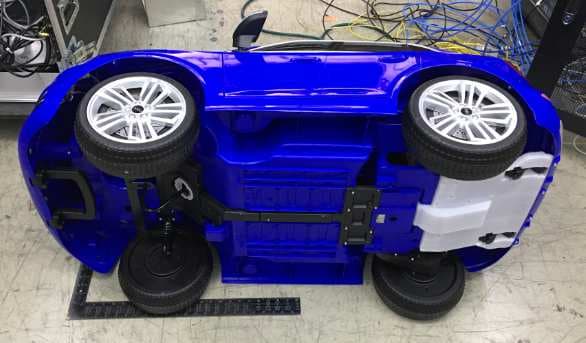
2ABGL-007
Mar 26, 2020KT1551I, KT1552I, KT1546I, KT1547I
Equipment Class
DSS - Part 15 Spread Spectrum Transmitter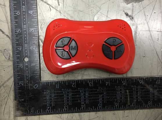
2ABGL-006
Mar 23, 20202.4G Remote Control
Equipment Class
DXX - Part 15 Low Power Communication Device Transmitter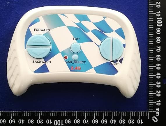
2ABGL-003
Mar 07, 20202.4G Remote Control
Equipment Class
DXX - Part 15 Low Power Communication Device Transmitter
2ABGLSW77771-2
Jan 19, 2014SCH CYCLENAV BIKE NAVIGATION
Equipment Class
DSS - Part 15 Spread Spectrum Transmitter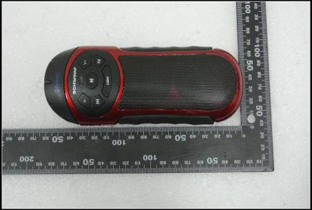
2ABGLSW77774-2
Jan 08, 2014Sch BluTunes Bike Speaker
Equipment Class
DSS - Part 15 Spread Spectrum Transmitter