2ACEVAXF353.5 inch smartphone
IED CONEXION VIRTUAL S.A. DE C.V.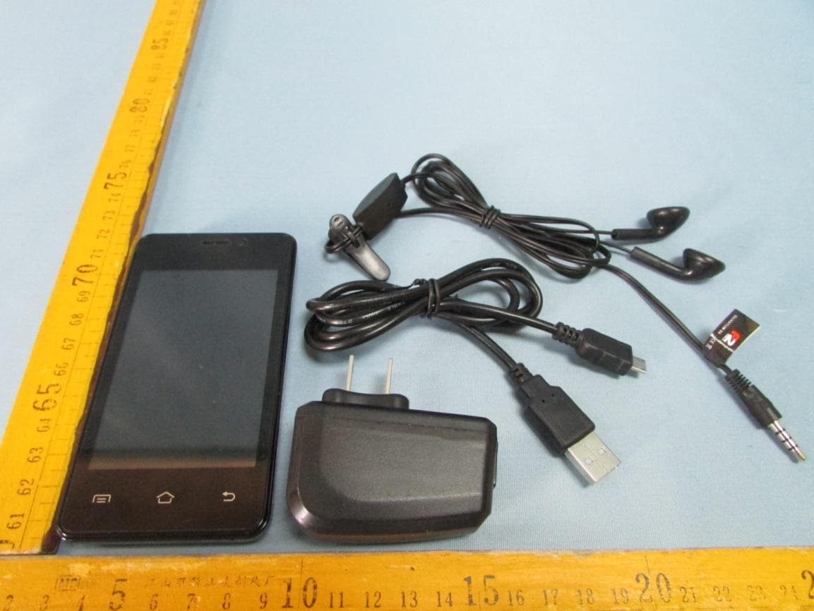
Click to zoom
Application Details
- Equipment Class
- PCE - PCS Licensed Transmitter held to ear
- Date of Grant
- Aug 06, 2014
- Application Purpose
- Original Equipment
- Date of Application
- Aug 06, 2014
- Equipment Note
- 3.5 inch smartphone
- Frequency Range
- 1852.40000000 - 1907.40000000
- Country
- Mexico
Documents & Files
Document Text
Text extracted from the exhibit documents filed with the FCC. Open a document above to read the original.
Users Manual
AX F35 User manual 1 / 45 AX F35 3.5 inch smartphone User Manual AX F35 User manual 2 / 45 Contents Welcome to use ................................................................................................................. 7 Safety and Maintenance .................................................................................................... 7 1. Brief of Functions ......................................................................................................... 10 Description of Keys ............................................................................................................. 10 Guide of the main functions ................................................................................................ 11 1.1 Dial a call ................................................................................................................... 11 1.2 Phonebook ................................................................................................................. 12 Notice Icons ........................................................................................................................ 12 Status Icons ........................................................................................................................ 13 2. Introduction ................................................................................................................ 14 2.1 Connect the network for the first time ...................................................................... 14 2.1.1 SIM Card ............................................................................................................... 14 2.1.2 Insert and take out the SIM Card ....................................................................... 15 2.1.3 Switch on /off the phone ....................................................................................... 15 2.1.4 Unlock the SIM card ............................................................................................ 15 2.1.5 Unlock the phone .................................................................................................. 15 2.1.6 Connect the network ............................................................................................ 16 2.1.7 Dial a call ............................................................................................................... 16 2.1.8 Dial domestic calls ................................................................................................ 16 2.1.9 Dial fixed-line telephone extension ...................................................................... 16 2.1.10 Answer calls ........................................................................................................ 16 2.1.11 Call menu ............................................................................................................ 16 3. Basic Operation .......................................................................................................... 17 3.1 Basic operation ............................................................................................................ 17 3.1.1 Exit menu .............................................................................................................. 17 3.1.2 Lock screen by one key ........................................................................................ 17 3.2 Menu structure ............................................................................................................ 17 3.2.1 Outer menu interface ................................................................................................ 17 AX F35 User manual 3 / 45 ....................................................................... 18 3.2.2 Enter the main menu interface ............................................................................. 18 3.2.3 Notice bar(background list) ............................................................................. 19 ................................................................. 20 AX F35 User manual 4 / 45 4. Usage Detail ................................................................................................................. 20 4.1 Dial a call ...................................................................................................................... 20 4.1.1 Enter the Dial Page ............................................................................................... 21 4.1.2 Video call ............................................................................................................... 21 4.1.3 Dial an emergency call ......................................................................................... 22 4.2 Receive or reject calls .................................................................................................. 23 4.2.1 Receive calls .......................................................................................................... 23 4.2.2 Reject calls ............................................................................................................. 23 4.2.3 Call options ........................................................................................................... 23 4.3 Call records .................................................................................................................. 24 4.3.1 Use call records ..................................................................................................... 24 4.3.2 Create new contacts .............................................................................................. 25 4.4 Activate and deactivate mobile phone function ........................................................ 26 4.4.1 Activate or deactivate flight mode. ..................................................................... 26 4.5 Create and manage of contacts ...............................................................................…
Text truncated - open the document above for the full version.
Cover Letter(s)
IED CONEXION VIRTUAL S.A DE C.V Rio Tiber # 103 Int 502 Colonia DF CP: 06500 Cuauhtemoc Mexico Date: June 1, 2014 Statement We, IED CONEXION VIRTUAL S.A DE C.V, states that our device, FCC ID: 2ACEVAXF35. According to FCC Part 2.925 rule, the label will put under the battery inside the battery compartment since limitation of the size, and it is visible to the users as they purchase the products and install the battery. Sincerely yours,
Cover Letter(s)
IED CONEXION VIRTUAL S.A DE C.V Federal Communications Commission Authorization and Evaluation Division 1435 Oakland Mills Road Columbia, MD 21046 Date: 2014.06.15 SUBJECT: FCC Application for FCC ID: 2ACEVAXF35 To Whom It May Concern: I, the undersigned, hereby attest to the fact that I will apply the Declaration of Conformity procedure to the class B computer peripheral portion of this composite device. I understand the following FCC requirements: 1. Devices subject to the DoC procedure are required to be tested to show compliance with the FCC technical regulations by a recognized accredited testing laboratory. The testing laboratory must be accredited by a Commission approved accreditation body or designated under the terms of a government-to-government Mutual Recognition Agreement (MRA). A listing of those accredited testing laboratories that have been recognized by the Commission is published on the FCC Webpage: https://apps.fcc.gov/oetcf/eas/reports/TestFirmSearch.cfm (Select the "accredited" option to search for FCC recognized accredited test firms.) 2. Test facilities located in countries, where the U.S. does not have an operational Telcom MRA are not recognized by the FCC to test for the DoC procedure. 3. Pt 2.1077 contains the list of information that must be included in the Declaration of Conformity, which must be supplied with each product sold. The DoC compliance info shall be included in the User’s Manual or as a separate sheet. The info must contain the name, address, and phone number of the responsible party, which must be located within the United States. According to 2.909(c)(2), the responsible party is either the Manufacturer or if the product is imported the Importer. Regards, Signature:(Must be signed by the person that is listed on the FCC Website) ...................................................
Cover Letter(s)
IED CONEXION VIRTUAL S.A DE C.V Date:2014-6-22 Subject: authorization for colors of battery cover To whom it May concern, Statement We would like to confirm the model AX F35 have different colors of battery cover, such as black, red, blue. Yours sincerely,
Cover Letter(s)
Page 1 of 1 Test Lab Attestation Letter Date of Test: 2014‐06‐19to 2014‐06‐27 Applicant Name: IED CONEXION VIRTUAL S.A DE C.V FCC Id: 2ACEVAXF35 Name of Engineer Performing Test: Silin Chen (Full Name, Typed) Statement of Compliance: Shenzhen SEM.Test Technology Co.,Ltd. declares that this Unit has been tested in accordance with the test method identified in this test report and that we observed it being tested. It also declares that the Unit complies with the relevant limits. All instrumentation and accessories used to test this unit for compliance to the indicated test method are calibrated regularly in accordance with ISO 17025:2005 requirements by laboratories accredited by A2LA, NVLAP, or ACLAS for the measurement parameters.
External Photos
Waltek Services (Shenzhen) Co.,Ltd. http://www.waltek.com.cn Photographs - Constructional Details Model AX F35- External View Waltek Services (Shenzhen) Co.,Ltd. http://www.waltek.com.cn Waltek Services (Shenzhen) Co.,Ltd. http://www.waltek.com.cn Waltek Services (Shenzhen) Co.,Ltd. http://www.waltek.com.cn Waltek Services (Shenzhen) Co.,Ltd. http://www.waltek.com.cn
ID Label/Location Info
FCC and IC Label Sample for model: AX F35 This device complies with part 15 of the FCC Rules. Operation is subject to the following two conditions: (1) This device may not cause harmful interference, and (2) this device must accept any interference received, including interference that may cause undesired operation. FCC ID: 2ACEVAXF35 Model: AX F35 This device complies with part 15 of the FCC Rules. Operation is subject to the following two conditions: (1) This device may not cause harmful interference, and (2) this device must accept any interference received, including interference that may cause undesired operation.
ID Label/Location Info
FCC and IC Label Sample for model: AX F35 This device complies with part 15 of the FCC Rules. Operation is subject to the following two conditions: (1) This device may not cause harmful interference, and (2) this device must accept any interference received, including interference that may cause undesired operation. FCC ID: 2ACEVAXF35 Model: AX F35 This device complies with part 15 of the FCC Rules. Operation is subject to the following two conditions: (1) This device may not cause harmful interference, and (2) this device must accept any interference received, including interference that may cause undesired operation.
Internal Photos
Waltek Services (Shenzhen) Co.,Ltd. http://www.waltek.com.cn Model AX F35- – Internal Photos Waltek Services (Shenzhen) Co.,Ltd. http://www.waltek.com.cn Waltek Services (Shenzhen) Co.,Ltd. http://www.waltek.com.cn
Parts List/Tune Up Info
Tune‐Up Procedure Tune‐Up Procedure ............................................................................................................................ 1 1 Purpose ...................................................................................................................................... 2 2 General descriptions ............................................................................................................ 2 2.1 Characteristics of the transmit burst ............................................................... 2 2.2 GPRS Data Transfer ................................................................................................. 3 3 Parameters ............................................................................................................................... 3 3.1 Parameters used to shape the burst ................................................................ 3 3.2 Parameters used to define the temporal position of the burst ............ 4 4 Operating mode ...................................................................................................................... 4 4.1 How to transmit a Tch burst (Random data), in PCS1900 mode, at power control level max: .............................................................................................. 4 4.2 How to stop Tx measurements: ......................................................................... 5 4.3 How to transmit a burst after modifying parameters .............................. 5 5 Purposes .................................................................................................................................... 5 6 Automatic frequency controls .......................................................................................... 5 7 Static frequency error and range .................................................................................... 7 8 Output Power .......................................................................................................................... 8 8.1 BAND GSM850 ........................................................................................................... 8 8.2 BAND PCS1900 .......................................................................................................... 8 8.3 GPRS Output Power ................................................................................................ 9 9 Tune‐Up WCDMA ................................................................................................................ 10 9.1 UMTS band 1900 Tx and 850 Tx .................................................................... 10 9.2 WCDMA OUTPOWER ........................................................................................... 10 1 Purpose This panel gives the possibility to manage the mobile in the transmit mode. This window includes both: ‐ All the parameters (frequency band, RF channel, RF level to get the desire antenna output power...) The user needs to make the mobile transmitting, ‐ All the parameters needed to define a transmit burst, ‐ All the compensation table to be able to align the mobile in production. This Tx_commands user guide is describing: ‐ The characteristics of the transmit burst, ‐ All the parameters used in the transmit mode, ‐ The operating mode to make the mobile transmitting 2 General descriptions 2.1 Characteristics of the transmit burst The power levels and the shape of a transmit burst are controlled by the power amplifier controller integrated in the ACPW. The burst is generated by a 10‐bit DAC from the ACPW as shown below: The ramping shape is referenced with the rising edge of Tx‐ON (from the Baseband). There are two types of parameters define the transmit burst: the first one define the shapes of the burst, and the second one define the temporal position of the burst. The rising and the falling edge of the transmit burst are determined by a set of 32 DAC code values n = 0 ... 31. Tru = TxTRUDefault + △TRU_P + △TRU_T Trd = TxTRD_NBDefault + △TRD_P (for a normal burst). Trd = TxTRD_ABDefault + △TRD_P (for an access burst). 2.2 GPRS Data Transfer GSM mobile phones use a Time Division Multiple Access (TDMA) scheme to transmit Data. The TDMA format contains eight time slots. The handset power amplifier typically transmits in up to four uplink slot. To prevent interference between cell phones, the time mask profile as specified is very restricted. To meet the GSM time mask, the output power of the PA needs to ramp up and down very quickly while staying within the time mask and not generating extraneous frequency bursts due to too abrupt ramp profiles. As described before, the Vramp input value sets the RF output power. By applying a certain ramp profile to the Vramp pin, the power level (Pout) of the PA is set to obtain the required time mask. A time mask of the PA’s output power is displayed. The time mask meets the limits (displayed by green lines) over a wide range of temperature, voltage and load variations. 3 Parameters F (n) are values coming from the DAC to shape the transmit burst. Some F(n) values have a corresponding Parameter used in the TAT to align the mobiles. Parameter used in TAT = [F (n)]. 3.1 Parameters used to shape the burst ‐ H0 = [F (1)] controls the rate at which energy is given to the control loop at the beginning of the ramp. This energy is needed to bring the PA system control in a closed loop. This is the second code coming from the APCW. ‐ PeakPow = [F (15)] corresponds to the peak power of the transmit burst. ‐ H30 = [F (30)] corresponds to the last ramping coefficients used to shape the ramp. ‐ MinPow = [F (31)] is a fixed parameter and corresponds to the Code Start of the AP6684 specification. It ensures a fast discharge of accumulated energy during the open loop mode in the summing node. 3.2 Parameters used to define the temporal position of the burst 3.2.1 Optimum position of the burst This parameter is TRU (or △TRU_P) on t…
Text truncated - open the document above for the full version.
RF Exposure Info
IED CONEXION VIRTUAL S.A DE C.V Model: AX F35 Report No.: STR14078267H Page 1 of 149 SAR Report FCC SAR Measurement and Test Report For IED CONEXION VIRTUAL S.A DE C.V Rio Tiber # 103 Int 502 Colonia DF CP: 06500 Cuauhtemoc Mexico FCC Rules: FCC 47 CFR Part 2 (2.1093) ANSI/IEEE C95.1-1992 IEEE 1528-2003 KDB 865664 D01 v01r03 KDB 865664 D02 v01r01 Product Description: 3.5 inch smartphone Tested Model: AX F35 Report No.: STR1478267H Tested Date: 2014-07-28 to 2014-07-30 Issued Date: 2014-07-30 Tested By: Silin Chen / Engineer Reviewed By: Lahm Peng / EMC Manager Approved & Authorized By: Jandy so / PSQ Manager Prepared By: Shenzhen SEM.Test Technology Co., Ltd. 1/F, Building A, Hongwei Industrial Park, Liuxian 2nd Road, Bao'an District, Shenzhen, P.R.C.(518101) Tel.: +86-755-33663308 Fax.: +86-755-33663309 Website: www.semtest.com.cn Note: This test report is limited to the above client company and the product model only. It may not be duplicated without prior permitted by Shenzhen SEM. Test Technology Co., Ltd. IED CONEXION VIRTUAL S.A DE C.V Model: AX F35 Report No.: STR14078267H Page 2 of 149 SAR Report TABLE OF CONTENTS 1. General Information ................................................................................................................................................... 3 1.1 Product Description for Equipment Under Test (EUT) ......................................................................................... 3 1.2 Test Standards .................................................................................................................................................... 5 1.3 Test Methodology ................................................................................................................................................ 5 1.4 Test Facility ......................................................................................................................................................... 5 2. Summary of Test Results .......................................................................................................................................... 6 3. Specific Absorption Rate (SAR) ................................................................................................................................ 7 3.1 Introduction .......................................................................................................................................................... 7 3.2 SAR Definition ..................................................................................................................................................... 7 4. SAR Measurement System ........................................................................................................................................ 8 4.1 The Measurement System .................................................................................................................................. 8 4.2 Probe ................................................................................................................................................................... 8 4.3 Probe Calibration Process ................................................................................................................................. 10 4.4 Phantom ............................................................................................................................................................ 11 4.5 Device Holder .................................................................................................................................................... 11 4.6 Test Equipment List ........................................................................................................................................... 12 5. Tissue Simulating Liquids ....................................................................................................................................... 13 5.1 Composition of Tissue Simulating Liquid ........................................................................................................... 13 5.2 Tissue Dielectric Parameters for Head and Body Phantoms ............................................................................. 14 5.3 Tissue Calibration Result ................................................................................................................................... 15 6. SAR Measurement Evaluation ................................................................................................................................ 16 6.1 Purpose of System Performance Check ............................................................................................................ 16 6.2 System Setup .................................................................................................................................................... 16 6.3 Validation Results .............................................................................................................................................. 17 7. EUT Testing Position ............................................................................................................................................... 18 7.1 Define Two Imaginary Lines on The Handset .................................................................................................... 18 7.2 Cheek Position .................................................................................................................................................. 19 7.3 Tilted Position .................................................................................................................................................... 19 7.4 Body Position .................................................................................................................................................... 20 7.5 EUT Antenna Position .......................................…
Text truncated - open the document above for the full version.
RF Exposure Info
IED CONEXION VIRTUAL S.A DE C.V Model: AX F35 Report No.: STR14078267H Page 81 of 149 SAR Report Maximum location: X=-55.00, Y=-63.00 SAR 10g (W/Kg) 0.033162 SAR 1g (W/Kg) 0.061869 Z (mm) 0.00 4.00 9.00 14.00 19.00 SAR (W/Kg) 0.0000 0.0659 0.0323 0.0160 0.0088 3D screen shot Hot spot position IED CONEXION VIRTUAL S.A DE C.V Model: AX F35 Report No.: STR14078267H Page 82 of 149 SAR Report MEASUREMENT 17 Type: Phone measurement (Complete) Date of measurement: 07/28/2014 Measurement duration: 12 minutes 3 seconds E-field Probe: SSE5 - SN 09/13 EP168; ConvF: 6.16; Calibrated: 03/21/2014 A. Experimental conditions Area Scan sam_direct_droit2_surf8mm.txt Phantom Left head Device Position Tilt Band GSM1900 Channels Low Signal TDMA (Crest factor: 8.0) B. SAR Measurement Results Frequency (MHz) 1909.800000 Relative Permittivity (real part) 41.0200000 Conductivity (S/m) 1.450000 Power Variation (%) -0.514000 Ambient Temperature 21.1 Liquid Temperature 21.3 SURFACE SAR VOLUME SAR IED CONEXION VIRTUAL S.A DE C.V Model: AX F35 Report No.: STR14078267H Page 83 of 149 SAR Report Maximum location: X=-20.00, Y=7.00 SAR 10g (W/Kg) 0.019162 SAR 1g (W/Kg) 0.035527 Z (mm) 0.00 4.00 9.00 14.00 19.00 SAR (W/Kg) 0.0000 0.0385 0.0219 0.0122 0.0068 3D screen shot Hot spot position IED CONEXION VIRTUAL S.A DE C.V Model: AX F35 Report No.: STR14078267H Page 84 of 149 SAR Report MEASUREMENT 18 Type: Phone measurement (Complete) Date of measurement: 07/28/2014 Measurement duration: 12 minutes 3 seconds E-field Probe: SSE5 - SN 09/13 EP168; ConvF: 6.30; Calibrated: 03/21/2014 A. Experimental conditions Area Scan sam_direct_droit2_surf8mm.txt Phantom Flat Plane Device Position Back(Body-worn) Band GSM1900 Channels High Signal TDMA (Crest factor: 8.0) B. SAR Measurement Results Frequency (MHz) 1909.800000 Relative Permittivity (real part) 53.960000 Conductivity (S/m) 1.560000 Power Variation (%) 0.768521 Ambient Temperature 21.1 Liquid Temperature 21.3 SURFACE SAR VOLUME SAR IED CONEXION VIRTUAL S.A DE C.V Model: AX F35 Report No.: STR14078267H Page 85 of 149 SAR Report Maximum location: X=13.00, Y=23.00 SAR 10g (W/Kg) 0.048888 SAR 1g (W/Kg) 0.088396 Z (mm) 0.00 4.00 9.00 14.00 19.00 SAR (W/Kg) 0.0000 0.0756 0.0417 0.0223 0.0118 3D screen shot Hot spot position IED CONEXION VIRTUAL S.A DE C.V Model: AX F35 Report No.: STR14078267H Page 86 of 149 SAR Report MEASUREMENT 19 Type: Phone measurement (Complete) Date of measurement: 07/28/2014 Measurement duration: 12 minutes 3 seconds E-field Probe: SSE5 - SN 09/13 EP168; ConvF: 6.30; Calibrated: 03/21/2014 A. Experimental conditions Area Scan sam_direct_droit2_surf8mm.txt Phantom Flat Plane Device Position Front(Body-worn) Band GSM1900 Channels High Signal TDMA (Crest factor: 8.0) B. SAR Measurement Results Frequency (MHz) 1909.800000 Relative Permittivity (real part) 53.960000 Conductivity (S/m) 1.560000 Power Variation (%) 0.768521 Ambient Temperature 21.1 Liquid Temperature 21.3 SURFACE SAR VOLUME SAR IED CONEXION VIRTUAL S.A DE C.V Model: AX F35 Report No.: STR14078267H Page 87 of 149 SAR Report Maximum location: X=-8.00, Y=-32.00 SAR 10g (W/Kg) 0.267537 SAR 1g (W/Kg) 0.527926 Z (mm) 0.00 4.00 9.00 14.00 19.00 SAR (W/Kg) 0.0000 0.4696 0.2421 0.1221 0.0628 3D screen shot Hot spot position IED CONEXION VIRTUAL S.A DE C.V Model: AX F35 Report No.: STR14078267H Page 88 of 149 SAR Report MEASUREMENT 20 Type: Phone measurement (Complete) Date of measurement: 07/28/2014 Measurement duration: 12 minutes 3 seconds E-field Probe: SSE5 - SN 09/13 EP168; ConvF: 6.30; Calibrated: 03/21/2014 A. Experimental conditions Area Scan sam_direct_droit2_surf8mm.txt Phantom Flat plane Device Position Back Band GPRS1900_4TX Channels Middle Signal Duty Cycle: 3.00 (Crest factor: 3.00) B. SAR Measurement Results Frequency (MHz) 1880.000000 Relative Permittivity (real part) 53.960000 Conductivity (S/m) 1.560000 Power Variation (%) 0.768521 Ambient Temperature 21.1 Liquid Temperature 21.3 SURFACE SAR VOLUME SAR IED CONEXION VIRTUAL S.A DE C.V Model: AX F35 Report No.: STR14078267H Page 89 of 149 SAR Report Maximum location: X=8.00, Y=-18.00 SAR 10g (W/Kg) 0.331095 SAR 1g (W/Kg) 0.656894 Z (mm) 0.00 4.00 9.00 14.00 19.00 SAR (W/Kg) 0.0000 0.7203 0.3683 0.1847 0.0950 3D screen shot Hot spot position IED CONEXION VIRTUAL S.A DE C.V Model: AX F35 Report No.: STR14078267H Page 90 of 149 SAR Report MEASUREMENT 21 Type: Phone measurement (Complete) Date of measurement: 07/28/2014 Measurement duration: 12 minutes 3 seconds E-field Probe: SSE5 - SN 09/13 EP168; ConvF: 6.30; Calibrated: 03/21/2014 A. Experimental conditions Area Scan sam_direct_droit2_surf8mm.txt Phantom Flat plane Device Position Front Band GPRS1900_4TX Channels Middle Signal Duty Cycle: 3.00 (Crest factor: 3.00) B. SAR Measurement Results Frequency (MHz) 1880.000000 Relative Permittivity (real part) 53.960000 Conductivity (S/m) 1.560000 Power Variation (%) 0.768521 Ambient Temperature 21.1 Liquid Temperature 21.3 SURFACE SAR VOLUME SAR IED CONEXION VIRTUAL S.A DE C.V Model: AX F35 Report No.: STR14078267H Page 91 of 149 SAR Report Maximum location: X=-8.00, Y=-23.00 SAR 10g (W/Kg) 0.061593 SAR 1g (W/Kg) 0.115799 Z (mm) 0.00 4.00 9.00 14.00 19.00 SAR (W/Kg) 0.0000 0.1231 0.0622 0.0310 0.0161 3D screen shot Hot spot position IED CONEXION VIRTUAL S.A DE C.V Model: AX F35 Report No.: STR14078267H Page 92 of 149 SAR Report MEASUREMENT 22 Type: Phone measurement (Complete) Date of measurement: 07/28/2014 Measurement duration: 12 minutes 3 seconds E-field Probe: SSE5 - SN 09/13 EP168; ConvF: 6.30; Calibrated: 03/21/2014 A. Experimental conditions Area Scan sam_direct_droit2_surf8mm.txt Phantom Flat plane Device Position Bottom Band GPRS1900_4TX Channels Middle Signal Duty Cycle: 3.00 (Crest factor: 3.00) B. SAR Measurement Results Frequency (MHz) 1880.000000 Relative Permittivity (real part) 53.960000 Conductivity (S/m) 1.560000 Power Variation (%) 0.768521 Ambient Temperature 21.1 Liquid Temperature 21.3 SURFACE SAR VOLUME SAR IED CONEXION VIRTU…
Text truncated - open the document above for the full version.
Test Report
Ref : ACR.88.1.13.SATU.A SEM TEST COMPLIANCE SERVICE CO., LTD. 3/F, JINGBAO COMMERCE BUILDING, XIN'AN FANSHEN ROAD, BAO'AN DISTRICT SHENZHEN (518101), CHINA SATIMO COMOSAR DOSIMETRIC E-FIELD PROBE SERIAL NO.: SN 09/13 EP168 Calibrated at SATIMO US 2105 Barrett Park Dr. - Kennesaw, GA 30144 06/19/2014 Summary: This document presents the method and results from an accredited COMOSAR Dosimetric E-Field Probe calibration performed in SATIMO USA using the CALISAR / CALIBAIR test bench, for use with a SATIMO COMOSAR system only. All calibration results are traceable to national metrology institutions. COMOSAR E-Field Probe Calibration Report COMOSAR E-FIELD PROBE CALIBRATION REPORT Ref: ACR.88.1.13.SATU.A Page: 2/10 This document shall not be reproduced, except in full or in part, without the written approval of SATIMO. The information contained herein is to be used only…
Text truncated - open the document above for the full version.
Contact Information
Applicant
ISAIAS MATRINEZ GONZALEZ(CEO)
Test Firm
Waltek Services(Shenzhen) Co., Ltd.Philo zhong
Technical Specifications
| # | Rule Parts | Frequency Range | Power Output | Emission | Tolerance |
|---|---|---|---|---|---|
| 4 | 24E | 1.85 GHz - 1.91 GHz | 142.00 mW | 4M17F9W | 0.005 ppm |
Other Applications from IED CONEXION VIRTUAL S.A. DE C.V.
2ACEVS8
Jul 06, 20144.5 INCH SMARTPHONE
Equipment Class
PCE - PCS Licensed Transmitter held to ear
2ACEVF2BRIOF25
May 22, 2014Mobile phone
Equipment Class
DTS - Digital Transmission System
2ACEVF2NEOF30
May 19, 2014Mobile phone
Equipment Class
PCE - PCS Licensed Transmitter held to ear