2ACGBHST915OM247 Home Station
G4S Monitoring Technologies Limited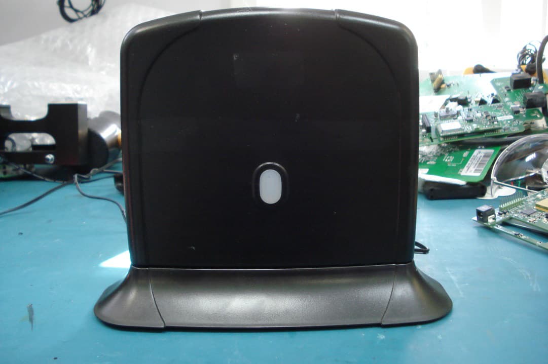
Click to zoom
Application Details
- Equipment Class
- DXT - Part 15 Low Power Transceiver, Rx Verified
- Date of Grant
- Sep 16, 2014
- Application Purpose
- Original Equipment
- Date of Application
- Sep 16, 2014
- Equipment Note
- OM247 Home Station
- Frequency Range
- 915.25000000 - 927.60000000
- Country
- United Kingdom
Documents & Files
Document Text
Text extracted from the exhibit documents filed with the FCC. Open a document above to read the original.
Users Manual
Document Classification: Public OM247-HS (Home Station) Safety Guide User Safety and Regulations Page 2Document Classification: Public This guide contains basic regulatory and safety information. Document Number: 94-0398-01 Revision: 1.0 Issue Date: 01/08/2014 About This Manual Page 3Document Classification: Public Operational Warnings Important information on safe and efficient operation. Read this information before using the device. For safe and efficient use of the device, observe the guidelines outlined below. International Protection Rating The device carries an IP rating of IP68 and as such can be immersed in water up to a depth of 5 metres. Environmental Specification 10% to 90% humidity (Battery Charger fitted) 0°C to +45°C (No Battery Charger fitted) -20°C to +60°C Installation The equipment must be installed by a SERVICE PERSON. Unit Record The model number, regulatory number and serial number are located on a nameplate on the rear of the device. Battery Charging When not in use, disconnect the battery charger from both the device and the mains electricity supply. To halt charging, remove the charging clip from the device. User Safety Page 4Document Classification: Public Do not disassemble, open, crush, deform or puncture the product. Do not modify, remanufacture, attempt to insert foreign objects, expose to fire, explosion or other hazards. Only use the product with an approved charger. Use of an unqualified charger may present a risk of fire, explosion, leakage or other hazard. Use only approved power accessories such as AC power adaptors. AC Power Adaptor Source: G4SMTL Model: SMC Part Number: 35-0092-3 Input Rating: 100-240V VAC, 50-60Hz, 350mA Output Rating: 5VDC, 3000mA Product Handling Page 5Document Classification: Public This equipment has been tested and found to comply with the limits for a Class B digital device, pursuant to part 15 of the FCC Rules. These limits are designed to provide reasonable protection against harmful interference in a residential installation. This equipment generates, uses and can radiate radio frequency energy and, if not installed and used in accordance with the instructions, may cause harmful interference to radio communications. However, there is no guarantee that interference will not occur in a particular installation. If this equipment does cause harmful interference to radio or television reception, which can be determined by turning the equipment off and on, the user is encouraged to try to correct the interference by one or more of the following measures: Reorient or relocate the receiving antenna. Increase the separation between the equipment and receiver. Connect the equipment into an outlet on a circuit different from that to which the receiver is connected. Consult the dealer or an experienced radio/TV technician for help. FCC Statements Page 6Document Classification: Public FCC Statements (continued) Modifications not expressly approved by the manufacturer could void the user’s authority to operate the equipment under FCC rules. This device complies with part 15 of the FCC Rules. Operation is subject to the following two conditions: 1. This device may not cause harmful interference. 2. This device must accept any interference received, including interference that may cause undesired operation. This product meets the FCC Radiofrequency Emission Guidelines and is certified with the FCC as: FCC ID: 2ACBHST915 The FCC ID is located on a label on the bottom of the product. Page 7Document Classification: Public We hereby declare that this device is in conformance to all essential requirements of the R&TTE Directive 1999/5/EC. This equipment is marked with the ‘CE’ symbol and can be used throughout the European Community. This indicates compliance with the R&TTE Directive 1999/5/ EC and meets the relevant parts of the following technical specifications: EN60950-1:2006 EN55022:2006 EN55024:1998 + A1:2001, A2:2003 EU Regulatory Conformance This symbol indicates that this product should be recycled and not be disposed of in unsorted municipal waste. This product should be returned to the supplier for correct disposal.
Attestation Statements
TRL 51F047 iss04
Cover Letter(s)
TRL 51F050 iss04 G4S Monitoring Technologies 3 Centurion Court Meridian East Meridian Business Park Leicester LE19 1TP REQUEST FOR CONFIDENTIALITY IN ACCORDANCE WITH FCC RULE 0.459 30/05/2014 TRaC GLOBAL LTD. 100 Frobisher Business Park Malvern Worcestershire WR14 1BX UK RE: Certification Application FCC ID: 2ACGBHST915 To Whom It May Concern: Please be advised that the following information is to be held confidential on behalf of G4S Monitoring technologies Ltd. • Track and Component Layout drawings • Technical documents: Home Station - System Overview • Block diagrams • Schematics • BOMs • Internal Photographs The application contains technical information which G4S Monitoring Technologies deems to be trade secrets and propriety. If made public, the information might be used to the disadvantage of the applicant in the market place. The product is a sealed device (welded in production) and a non-consumer device serviceable only by the grantee. Thank you for your attention to this matter. Yours faithfully G4S Monitoring Technologies Ltd
External Photos
G4S Monitoring Technologies Ltd Issue Date: 12/08/2014 Version: 1.0 Document Owner: Fiona Farrer Current Date: 12/08/14 Page 1 of 5 Home Station 915MHz External Photographs COPYRIGHT STATEMENT This document and the information contained therein is the property of G4S Monitoring Technologies Ltd. It must not be reproduced in whole or part or otherwise disclosed without prior written consent of the G4S Monitoring Technologies Ltd Quality Manager or Quality Director. Home Station 915MHz External Photographs Page 2 of 5 Contents 1 External: Complete ................................................................................................ 3 2 External: Top Case containing main pcb ............................................................... 3 3 External: Underside of Top case ........................................................................... 4 4 External: Inside of Plinth ........................................................................................ 4 5 External: Underside of Plinth ................................................................................. 5 Home Station 915MHz External Photographs Page 3 of 5 1 External: Complete 2 External: Top Case containing main pcb Home Station 915MHz External Photographs Page 4 of 5 3 External: Underside of Top case 4 External: Inside of Plinth Home Station 915MHz External Photographs Page 5 of 5 5 External: Underside of Plinth
ID Label/Location Info
G4S Monitoring Technologies Ltd +/- 1 +0.25 -0 +0.10 -0 +0.05 -0 +0 -0.25 +0 -0.10 +0 -0.05 X X.X X.XX 2:1 A 1245 A 2145 A4 NW 01 96-0190-4 A-700-MP POLYESTER SILVER THERMAL TRANSFER PRINTED AS DRAWING FCC RCM HOME STATION LABEL DRAWING 22/05/14 Document Classification: CONFIDENTIAL HSTGMTXXXXXX HSTGMT750041 3.0 25.0 FCC RCM HOME STATION CODE128 BARCODE NOTES - 1. DIMENSIONS FOR INSPECTION PURPOSES ONLY. FOR ALL OTHER DIMENSIONS REFER TO - 96-0164-4 FCC RCM HOME STATION LABEL DRAWING.AI 2. PRINTED ON ADVANCED LABELS A-700-MP SILVER THERMAL TRANSFER POLYESTER LABEL STOCK 104μm THICK P/N 96-0130-4. 3. PRINTED COLOURS: TEXT AND LOGOS BLACK. 4. BACKED WITH 20μm #310 ACRYLIC ADHESIVE. 5. USE TRUE TYPE FONT: ARIEL SIZE 8 POINT. S/N FONT ARIAL 8 POINT ON CL 2.5 7.0 FCC ID: 2ACGBHST915 SYMBOL MUST BE EQUALLY SPACED AND A MINIMUM OF 5MM TALL 35.0
ID Label/Location Info
G4S Monitoring Technologies Ltd Issue Date: 12/08/2014 Version: 1.0 Document Owner: Fiona Farrer Current Date: 12/08/14 Page 1 of 4 Home Station 915MHz Label position COPYRIGHT STATEMENT This document and the information contained therein is the property of G4S Monitoring Technologies Ltd. It must not be reproduced in whole or part or otherwise disclosed without prior written consent of the G4S Monitoring Technologies Ltd Quality Manager or Quality Director. Home Station 915MHz Label Position Page 2 of 4 Contents 1 FCC Label Position................................................................................................ 3 Home Station 915MHz Label Position Page 3 of 4 1 FCC Label Position The FCC label is to be positioned on the underside of the main case, visible through a hole on the underside of the plinth. The plinth is tamper riveted to the main case so the label can be viewed but is not easily accessible by anyone. Complete Unit: Top case Plinth FCC Label as detailed in FCC label artwork located on underside of Top Case in place of this representative label Home Station 915MHz Label Position Page 4 of 4 Plinth has hole for label on top case to be viewed from underside of plinth Tamper rivet hole Tamper rivet locks plinth and top case together
Test Report
A RADIO TEST REPORT FOR G4S Monitoring Technologies LTD ON OM247 Home Station 915MHz 10-0166-4 DOCUMENT NO.TRA-016455WUS5A Total number of pages: 47 TRaC Wireless Test Report : TRA-016455WUS5A Applicant : G4S Monitoring Technologies Ltd. Apparatus : OM247 Home Station 915MHz 10-0166-4 Specification(s) : CFR47 Part 15.249 Purpose of Test : Certification FCCID : 2ACGBHST915 Authorised by : : Radio Product Manager Issue Date : 16 th September 2014 Authorised Copy Number : PDF TRaC Global Test Report: TRA-016455WUS5A 3 Contents Section 1: Introduction 4 1.1 General 4 1.2 Tests Requested By 5 1.3 Manufacturer 5 1.4 Apparatus Assessed 5 1.5 Test Result Summary 6 1.6 Notes Relating To The Assessment 7 1.7 Deviations from Test Standards 7 Section 2 General Test Procedures 8 2.1 Radiated Test Setup and Procedures 8 2.2 AC Powerline Conducted Emissions Test Setup and Procedures 9 2.3 Antenna Port Conducted Emissions 9 2.4 Power Supply Variation 10 2.5 Thermal Variation 10 2.6 Time Domain Measurements 10 Section 3: Measurement Uncertainty 11 3.1 Measurement Uncertainty Values 11 Section 4: Modifications 12 4.1 Modifications Performed During Assessment 12 Appendix A: Formal Emission Test Results 13 A1 Transmitter Intentional Emission Radiated 14 A2 Transmitter Bandwidth 15 A3 Radiated Electric Field Emissions 16 A4 Unintentional Radiated Emissions 19 A5 Power Line Conducted Spurious Emissions 21 Appendix B: Supporting Graphical Data 25 Appendix C: Additional Test and Sample Details 34 Appendix D: Additional Information 40 Appendix E: Calculation of the duty cycle correction factor 41 Appendix F: Photographs and Figures 42 Appendix G: General SAR test reduction and exclusion guidance 46 TRaC Global Test Report: TRA-016455WUS5A 4 Section 1: Introduction 1.1 General This report contains an assessment of an apparatus against Electromagnetic Compatibility Standards based upon tests carried out on samples submitted to the Laboratory. Test performed by: TRaC Global [X] Unit E South Orbital Trading Park Hedon Road Hull, HU9 1NJ. United Kingdom. Telephone: +44 (0) 1482 801801 Fax: +44 (0) 1482 801806 TRaC Global [ ] Unit 1 Pendle Place Skelmersdale West Lancashire, WN8 9PN United Kingdom Telephone: +44 (0) 1695 556666 Fax: +44 (0) 1695 577077 Email: [email protected] Web site: http://www.tracglobal.com Tests performed by: A Longley Report author: A Longley This report must not be reproduced except in full without prior written permission from TRaC Global. TRaC Global Test Report: TRA-016455WUS5A 5 1.2 Tests Requested By This testing in this report was requested by: G4S Monitoring Technologies Ltd. 3 Centurion Court Meridian Business Park Leicester LE19 1TP United Kingdom 1.3 Manufacturer As Above 1.4 Apparatus Assessed The following apparatus was assessed between 07 th July 2014 – 11 th July 2014: OM247 Home Station 915MHz 10-0166-4 The above device is a Monitoring Unit for an ankle monitor containing a Radio Transceiver operating on 2 fixed frequencies (915.25 & 927.6 MHz) in the 902 – 928 MHz band. TRaC Global Test Report: TRA-016455WUS5A 6 1.5 Test Result Summary Full details of test results are contained within Appendix A. The following table summarises the results of the assessment. The statements relating to compliance with the standards below apply ONLY as qualified in the notes and deviations stated in sections 1.6 to 1.7 of this test report. Full details of test results are contained within Appendix A. The following table summarises the results of the assessment. Test Type Regulation Measurement standard Result Title 47 of the CFR: Part 15 Subpart (c) Intentional Emission Field Strength 15.249 (a) ANSI C63.10:2009 Pass Intentional Emission Band Occupancy 15.215 (c) ANSI C63.10:2009 Pass Spurious Emissions Radiated <1000MHz 15.209 & 15.249 (a) (d) ANSI C63.10:2009 Pass Unintentional Radiated Spurious Emissions 15.109 ANSI C63.10:2009 Pass Power Line Conducted Spurious Emissions 15.207 ANSI C63.10:2009 Pass Abbreviations used in the above table: CFR : Code of Federal Regulations ANSI : American National Standards Institution REFE : Radiated Electric Field Emissions PLCE : Power Line Conducted Emissions TRaC Global Test Report: TRA-016455WUS5A 7 1.6 Notes Relating To The Assessment With regard to this assessment, the following points should be noted: The results contained in this report relate only to the items tested and were obtained in the period between the date of initial receipt of samples and the date of issue of the report. The apparatus was set up and exercised using the configurations, modes of operation and arrangements defined in this report only. Particular operating modes, apparatus monitoring methods and performance criteria required by the standards tested to have been performed except where identified in Section 1.7 of this test report (Deviations from Test Standards). For emissions testing, throughout this test report, “Pass” indicates that the results for the sample as tested were below the specified limit (refer also to Section 2, Measurement Uncertainty). Where relevant, the apparatus was only assessed using the monitoring methods and susceptibility criteria defined in this report. All testing was performed under the following environmental conditions: Temperature : 17 to 23 °C Humidity : 45 to 75 % Barometric Pressure : 86 to 106 kPa All dates used in this report are in the format dd/mm/yy. This assessment has been performed in accordance with the requirements of CFR47 Part 2 & RSS-Gen. 1.7 Deviations from Test Standards There were no deviations from the standards tested to. TRaC Global Test Report: TRA-016455WUS5A 8 Section 2 General Test Procedures 2.1 Radiated Test Setup and Procedures Radiated electromagnetic emissions from the EUT are checked first by preview scans. Preview scans for all spectrum and modulation characteristics are checked, using a peak detector and where applicable worst case determined for function, operation, orientation etc for both vertical and horizont…
Text truncated - open the document above for the full version.
Contact Information
Applicant
Aled Hughes(Mr)
Test Firm
Element Materials Technology Warwick LtdMax Leach
Technical Specifications
| # | Rule Parts | Frequency Range | Power Output |
|---|---|---|---|
| 1 | 15C | 915.25 MHz - 927.6 MHz | - |
Other Applications from G4S Monitoring Technologies Limited
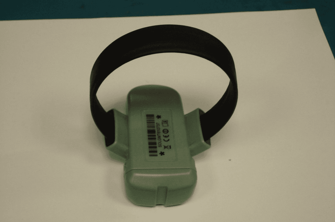
2ACGBSOL915
Apr 29, 2015OM247 SOLO2
Equipment Class
DXT - Part 15 Low Power Transceiver, Rx Verified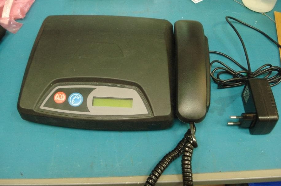
2ACGBMCM3915
Jul 13, 2014OM247 MU3 MultiCom
Equipment Class
DXX - Part 15 Low Power Communication Device Transmitter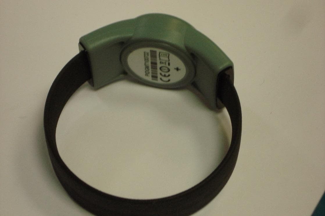
2ACGBPID915
Jun 24, 2014OM247 PID3
Equipment Class
DXX - Part 15 Low Power Communication Device Transmitter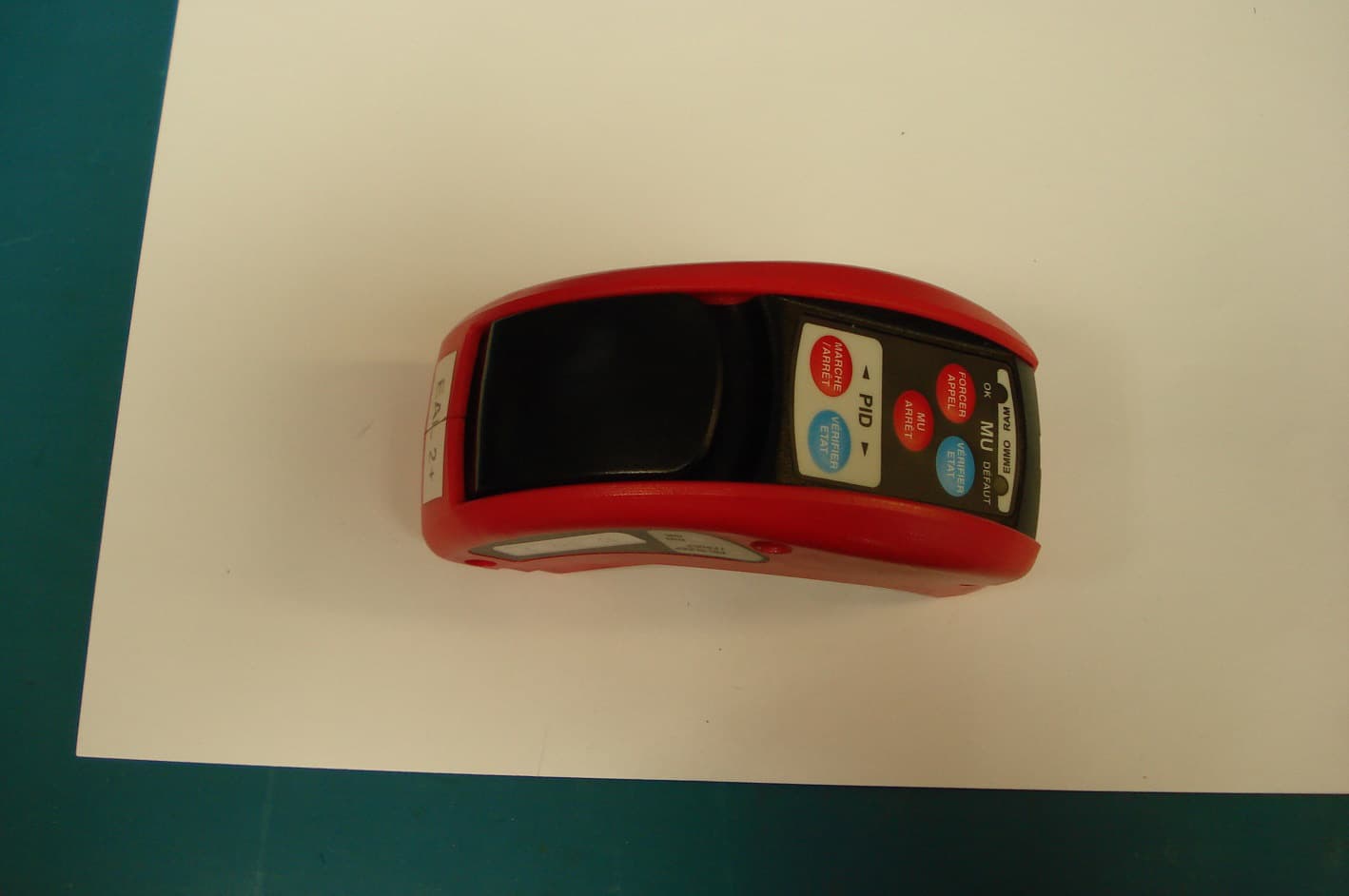
2ACGBFIT915
Jun 24, 2014OM247 FIT3
Equipment Class
DXX - Part 15 Low Power Communication Device Transmitter