2ACK6AMP100Amplifier
CABASSE SA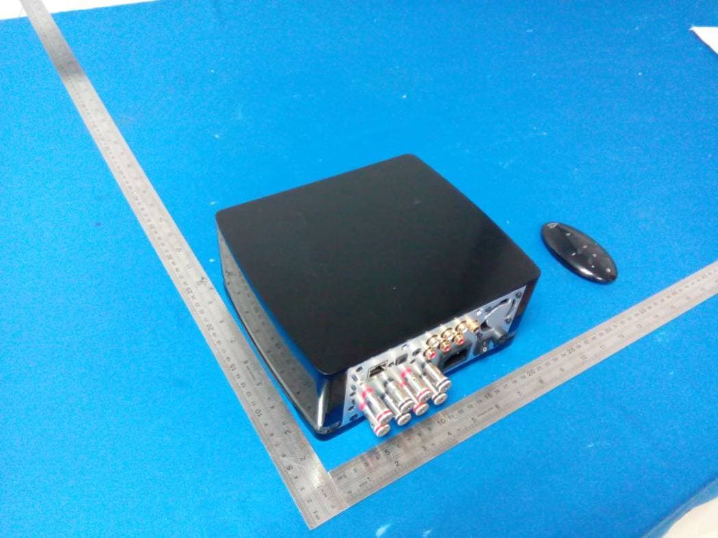
Click to zoom
Application Details
- Equipment Class
- DTS - Digital Transmission System
- Date of Grant
- Nov 17, 2014
- Application Purpose
- Original Equipment
- Date of Application
- Nov 17, 2014
- Equipment Note
- Amplifier
- Frequency Range
- 2412.00000000 - 2462.00000000
- Company
- CABASSE SA
- Country
- France
Documents & Files
Document Text
Text extracted from the exhibit documents filed with the FCC. Open a document above to read the original.
Users Manual
notice d'installation owner's manual betriebsanleitung 用户手册 stream amP 100 www.cabasse.com f r a n c a i s 22 3 218 190 91 218 f r a n c a i s 44 1 11 8 3 4 10 2 9 IDENTIFICATION DES COMMANDES 1LED DISPLAYMARCHE (diode blanche)/ ECO(diode rouge) 2VOL -Diminution du volume 3VOL +Augmentation du volume 4 Active et désactive la coupure du son 8 Selection de la source 9SOURCES BLUETOOTH - WIFI (WiFi/Ethernet) - RCA ANALOG 1 - RCA ANALOG 2 - OPTIQUE 10 Position du patch NFC 5 1 2 5 7 3 4 6 8 IDENTIFICATION DES COMMANDES 1MARCHE / ECO 2VOL -Diminution du volume 3VOL +Augmentation du volume 4 Activation et désactivation de la coupure du son 5 Titre précédent de l'album en cours de lecture 6 Titre suivant de l'album en cours de lecture 7Pause/Lecture 8 Selection de la source FONCTIONS Connexion Bluetooth WIFI/ETHERNET via routeur internet / box internet WIFI direct smartphone/ tablette Diffusion audio loss less 44 Accès à tous les supports audio depuis le reseau WIFI (ordinateur...) 4 Multi-room 4 Diffusion des contenus audio smartphone/tablette 444 Diffusion application audio (youtube...) depuis smartphone/ tablette 4 Diffusion à partir de supports USB 44 Web radio /DEEZER 4 Fabriqué sous licence de Dolby Laboratories. Dolby et le symbole du double D sont des marques déposées de Dolby Laboratories. f r a n c a i s 6 INSTALLATION RAPIDE Installer votre STREAM AMP à proximité d'une prise de courant. Prévoir un espace suffisant autour, dessous (sur une surface solide et plane) et au dessus de l'appareil pour un bon fonctionnent des antennes Bluetooth et WIFI et une bonne ventilation de l'électronique de puissance. La face avant de l'appareil doit rester visible. Brancher 2 ou 4 enceintes aux bornes de STREAM AMP. Si 2 enceintes, choisir la sortie SP1 pour l’enceinte droite, la sortie SP2 pour la gauche. ATTENTION: respecter les polarités en reliant les bornes + entre elles et bien connecter les sorties gauche (L) aux entrées gauche (L). Sélecteur d’impédance: Position « I » (réglage usine) : STREAM AMP délivre 2 x 50 W ou 4 x 25 W RMS pour les enceintes avec une impédance minimum inférieure à 6,4 ohms, 2 x 25 W ou 4 x 12,5 W avec des impédances supérieures. Position « II » : à utiliser avec des enceintes acoustiques dont l’impédance minimum est supérieure ou égale à 6,4 ohms pour obtenir 2 x 50 W ou 4 x 25 W RMS. Choisir cette position pour les modèles Cabasse de la gamme Archipel et pour Antigua IW. Connecter le câble d'alimentation au STREAM AMP puis au secteur et basculer l'interrupteur marche/arrêt sur "on". STREAM AMP est opérationnel dès que la diode 1 s'allume en rouge (mode ECO). Passer en mode MARCHE en appuyant sur la touche 1 du STREAM AMP ou de la télécommande. NOTE : la fonction DLNA de STREAM AMP devient opérationnelle lorsque la diode PWR (power) est passée du rouge au vert, environ 40 secondes après la mise sous tension. 2 1 7 3 Paramétrage des sorties enceintes. Sélectionner une des 4 options par appuis successifs sur la touche après la première mise en route du Stream Amp: - 1 paire d’enceintes en STEREO (réglage par défaut). Les diodes SP1, SP2, STEREO sont allumées. - 2 paires d’enceintes en STEREO. Les diodes SP1, SP2, SP3, SP4 et STEREO sont allumées. - 2 enceintes en MONO. Les diodes SP1, SP2, MONO sont allumées. - 4 enceintes en MONO. Les diodes SP1, SP2, SP3, SP4 et MONO sont allumées. Avant la première utilisation, dévisser la vis (tournevis PH00), enlever le couvercle, retirer la languette de protection, remettre le couvercle et resserrer la vis. . Remplacement de la pile bouton type CR-2025 : retourner la télécommande, dévisser la vis, enlever le couvercle, enlever la pile usagée, insérer la pile neuve, coté marquée "+" vers l'extérieur, remettre le couvercle, resserrer la vis. 4 f r a n c a i s 8 ENTREES ANALOGIQUES 1 ET 2 Choisissez les entrées 1 ou 2 pour pour connecter une source audio (TV, lecteur CD, lecteur MP3, smartphone) équipée d'une sortie analogique type RCA ou mini-jack. Pour un appareil équipé d'une sortie mini-jack, utiliser un cordon mini-jack/RCA (non fourni). ENTREE USB Connecter une clé USB ou un disque dur contenant des fichiers audio à cette entrée pour les mettre automatiquement en réseau. Tous les fichiers aux formats reconnus par le serveur DLNA inclus dans STREAM AMP sont alors listés dans l'application Stream Audio Control et peuvent être lus par tous les lecteurs Cabasse Stream connectés au même réseau. La prise USB de STREAM AMP est pourvue d'une alimentation de 1 ampère pour l'utilisation d'un disque dur nomade sans recours à une alimentation externe. 5 6 7 Une fois les connexions Bluetooth et Wi-Fi/Ethernet activées (voir chapitres suivants), sélectionner la source avec des appuis successifs sur la touche 8 de la télécommande Stream ou de la face-avant du Stream Amp. Le Stream Amp affiche l'entrée sélectionnée. La LED Wi-fi représente la connexion Wi-Fi, la LED ETH représente la connexion réseau. La solution Ethernet est prioritaire. 9 CONNEXION BLUETOOTH Le STREAM AMP est configuré en mode ouvert pour les connexions Bluetooth. il suffit donc, dans le menu de l'appareil à connecter, de sélectionner "Cabasse STREAM AMP" dans la liste des appareils Bluetooth disponibles. Sélectionner si nécessaire la source Bluetooth en pressant le bouton 8 de la télécommande "Stream" ou de Stream Amp jusqu'à ce que la diode 9 BLUETOOTH s'illumine. Si un appareil est déjà connecté en Bluetooth avec STREAM AMP, il faut interrompre cette liaison avant d'en réaliser une nouvelle avec un autre appareil. EXEMPLE DE CONNEXION BLUETOOTH AVEC UNE TABLETTE ANDROID : voir la version française en page 16. CONNEXION ET UTILISATION AVEC UN ORDINATEUR APPLE: version française en page 17. CONNEXION BLUETOOTH INSTANTANEE AVEC UN SMARTPHONE NFC 1) Installation de l'application NFC Cabasse a) Activer le mode NFC dans le menu de votre smartphone NFC. b) Vérifier/activer la connexion du smartphone à Internet (réseau cellulaire wifi ou 3G, 4G). c) Approcher le smartphone du patc…
Text truncated - open the document above for the full version.
Cover Letter(s)
SCS-F18: Project and Product Certification Representative Authorization Letter Page 1 of 2 Rev 5.0 775 Montague Expressway Milpitas, CA 95035 Tel: 408-526-1188 Fax: 408-526-1088 Email: [email protected] Project and Product Certification Representative Authorization Letter Revision History Reason for Amendment (current / obsolete) From To Approved Date Initial Release (obsolete) 1.0 1.0 Nov-14-2006 Revised wording (obsolete) 1.0 2.0 Sept–25-2007 Updated company template (obsolete) 2.0 3.0 Jan-31-2012 Updated letter information (obsolete) 3.0 4.0 May-23-2014 Added FCC ID field (current) 4.0 5.0 Sept 16 2014 SCS-F18: Project and Product Certification Representative Authorization Letter Page 2 of 2 Rev 5.0 CABASSE SA 210. RUE RENE DESCARTES-BP 10,29280 PLOUZANE, FRANCE 2014-11-1 To: SIEMIC, INC. 775 Montague Expressway, Milpitas, CA 95035 USA Dear Sir/Madam, Re: Product Certification Representative Authorization Letter We, CABASSE SA hereby authorize SIEMIC, Inc. to act as a Certification Body for certifying for the following project(s): FCC ID: 2ACK6AMP100 Model: Stream Amp 100 Product: Amplifier Sincerely, signature : name / title: KERNEIS David / Electronic engineer address: 210. RUE RENE DESCARTES-BP 10,29280 PLOUZANE, FRANCE
Cover Letter(s)
SCS-F19: Confidentiality Request Letter Page 1 of 2 Rev 3.0 775 Montague Expressway Milpitas, CA 95035 Tel: 408-526-1188 Fax: 408-526-1088 Email: [email protected] Confidentiality Request Letter Revision History Reason for Amendment (current / obsolete) From To Approved Date Initial Release (obsolete) 1.0 1.0 Nov-14-2006 Adding CFR 2.459 (obsolete) 1.0 2.0 August – 11 - 2008 Updated company template & Added text box (current) 2.0 3.0 Jan-31-2012 SCS-F19: Confidentiality Request Letter Page 2 of 2 Rev 3.0 CABASSE SA 210. RUE RENE DESCARTES-BP 10,29280 PLOUZANE, FRANCE 2014-11-1 To: Federal Communications Commission Authorization and Evaluation Division 7435 Oakland Mills Road Columbia, MD Subject: Permanent Confidentiality Request for FCC ID: 2ACK6AMP100 We hereby request confidential treatment of information accompanying this application as outlined below: Block Diagram Schematics Operational Description The above materials contain trade secrets and proprietary information not customarily released to the public. The public disclosure of these materials may be harmful to the applicant and provide unjustified benefits to its competitors. The applicant understands that pursuant to Section 0.457 & 0.459 of the Rules, disclosure of this application and all accompanying documentation will not be made before the date of the Grant for this application. Sincerely, signature : name / title: KERNEIS David / Electronic engineer address: 210. RUE RENE DESCARTES-BP 10,29280 PLOUZANE, FRANCE
Cover Letter(s)
CABASSE SA 210. RUE RENE DESCARTES-BP 10,29280 PLOUZANE, FRANCE FCC ID: 2ACK6AMP100 To Whom It May Concern: We, the undersigned, hereby attest to the fact that we will apply the Declaration of Conformity procedure to the class B computer peripheral portion of this composite device. We understand that devices subject to the DoC procedure are required to be tested to show compliance with the FCC technical regulations by a recognized accredited testing laboratory. The testing laboratory must be accredited by a Commission approved accreditation body or designated under the terms of a government-to-government Mutual Recognition Agreement (MRA). A listing of those accredited testing laboratories that have been recognized by the Commission is published on the FCC Test facilities located in countries, where the U.S. does not have an operational Telcom MRA are not recognized by the FCC to test for the DoC procedure. Sincerely, signature : name / title: KERNEIS David / Electronic engineer address: 210. RUE RENE DESCARTES-BP 10,29280 PLOUZANE, FRANCE
ID Label/Location Info
Label location
Internal Photos
BT Antenna WIFI Antenna
RF Exposure Info
FCC ID: 2ACK6AMP100 1. RF EXPOSURE EVALUATION 1.1. Limits The criteria listed in the following table shall be used to evaluate the environment impact of human exposure to radio frequency (RF) radiation as specified in 1.1307(b) Limits for Maximum Permissible Exposure (MPE) f = frequency in MHz Friis transmission formula: Pd = (Pout*G)/(4*pi*r 2 ) Where Pd = power density in mW/cm 2 , Pout = output power to antenna in mW; G = gain of antenna in linear scale, Pi = 3.1416; R = distance between observation point and center of the radiator in cm Pd id the limit of MPE, 1 mW/cm 2 . If we know the maximum gain of the antenna and the total power input to the antenna, through the calculation, we will know the distance r where the MPE limit is reached. 1.2. Test Procedure Software provided by client enabled the EUT to transmit and receive data at lowest, middle and highest channel individually. FCC ID: 2ACK6AMP100 1.3. Test Result of RF Exposure Evaluation Target power W/ tolerance (dBm) Max tune up power tolerance (dBm) Output power to antenna (mW) Antenna Gain(dBi) Power Density at R=20cm (mW/cm 2 ) Limit (mW/cm 2 ) Result 802.11b 16 ±1.0 17.0 50.12 1.0 0.01255 1.0 Pass 802.11g 13 ±1.0 14.0 25.12 1.0 0.00629 1.0 Pass 802.11n (HT20) 12 ±1.0 13.0 19.95 1.0 0.00500 1.0 Pass 802.11n (HT40) 11 ±1.0 12.0 15.85 1.0 0.00397 1.0 Pass
Test Report
FCC ID: 2ACK6AMP100 Keyway Testing Technology Co., Ltd. Report No. 14KWE11199902F Page 1 of 57 FCC TEST REPORT for CABASSE SA Amplifier Model Number: Stream Amp 100 FCC ID: 2ACK6AMP100 Prepared for : CABASSE SA Address : 210. RUE RENE DESCARTES-BP 10, 29280 PLOUZANE, FRANCE Prepared by : Keyway Testing Technology Co., Ltd. Address : Building 1, Baishun Industrial Zone, Zhangmotou Town, Dongguan, Guangdong, China Report No. : 14KWE11199902F Date of Test : Nov. 1~5, 2014 Date of Report : Nov. 5, 2014 FCC ID: 2ACK6AMP100 Keyway Testing Technology Co., Ltd. Report No. 14KWE11199902F Page 2 of 57 TABLE OF CONTENTS Test Report Declaration Page 1. TEST SUMMARY .................................................................................................................................4 2. GENERAL PRODUCT INFORMATION ...............................................................................................4 2.1. Product Function...........................................................................................................................4 2.2. Description of Device (EUT) .........................................................................................................4 2.3. Independent Operation Modes .....................................................................................................5 2.4. Test Supporting System................................................................................................................5 3. TEST SITES .........................................................................................................................................6 3.1. Test Facilities ................................................................................................................................6 3.2. List of Test and Measurement Instruments...................................................................................7 4. TEST SET-UP AND OPERATION MODES .........................................................................................8 4.1. Principle of Configuration Selection ..............................................................................................8 4.2. Block Diagram of Test Set-up .......................................................................................................8 4.3. Test Operation Mode and Test Software ......................................................................................8 4.4. Special Accessories and Auxiliary Equipment ..............................................................................8 4.5. Countermeasures to Achieve EMC Compliance...........................................................................8 5. EMISSION TEST RESULTS ................................................................................................................9 5.1. Conducted Emission at the Mains Terminals Test........................................................................9 5.2. Radiated Emission Test ..............................................................................................................12 6. 6DB OCCUPY BANDWIDTH .............................................................................................................30 6.1. Limits...........................................................................................................................................30 6.2. Test setup ...................................................................................................................................30 6.3. Test result ...................................................................................................................................30 7. BAND EDGE COMPLIANCE TEST ...................................................................................................37 7.1. Limits...........................................................................................................................................37 7.2. Test setup ...................................................................................................................................37 8. OUTPUT POWER TEST ....................................................................................................................39 8.1. Limits...........................................................................................................................................39 8.2. Test setup ...................................................................................................................................39 8.3. Test result ...................................................................................................................................39 9. POWER SPECTRAL DENSITY TEST ...............................................................................................40 9.1. Limits...........................................................................................................................................40 9.2. Test setup ...................................................................................................................................40 9.3. Test result ...................................................................................................................................40 10. ANTENNA REQUIREMENTS ..........................................................................................................43 10.1. Limits.........................................................................................................................................43 10.2. Result........................................................................................................................................43 11. PHOTOGRAPHS OF TEST SET-UP ...............................................................................................44 12. PHOTOGRAPHS OF THE EUT .................................................................................................…
Text truncated - open the document above for the full version.
Test Report
FCC ID: 2ACK6AMP100 Keyway Testing Technology Co., Ltd. Report No. 14KWE11199902F Page 46 of 57 12. PHOTOGRAPHS OF THE EUT FCC ID: 2ACK6AMP100 Keyway Testing Technology Co., Ltd. Report No. 14KWE11199902F Page 47 of 57 FCC ID: 2ACK6AMP100 Keyway Testing Technology Co., Ltd. Report No. 14KWE11199902F Page 48 of 57 FCC ID: 2ACK6AMP100 Keyway Testing Technology Co., Ltd. Report No. 14KWE11199902F Page 49 of 57 FCC ID: 2ACK6AMP100 Keyway Testing Technology Co., Ltd. Report No. 14KWE11199902F Page 50 of 57 FCC ID: 2ACK6AMP100 Keyway Testing Technology Co., Ltd. Report No. 14KWE11199902F Page 51 of 57 FCC ID: 2ACK6AMP100 Keyway Testing Technology Co., Ltd. Report No. 14KWE11199902F Page 52 of 57 FCC ID: 2ACK6AMP100 Keyway Testing Technology Co., Ltd. Report No. 14KWE11199902F Page 53 of 57 FCC ID: 2ACK6AMP100 Keyway Testing Technology Co., Ltd. Report No. 14KWE11199902F Page 54 of 57 FCC ID: 2ACK6AMP100 Keyway Testing Technology Co., Ltd. Report No. 14KWE11199902F Page 55 of 57 FCC ID: 2ACK6AMP100 Keyway Testing Technology Co., Ltd. Report No. 14KWE11199902F Page 56 of 57 FCC ID: 2ACK6AMP100 Keyway Testing Technology Co., Ltd. Report No. 14KWE11199902F Page 57 of 57 ------END------
Test Setup Photos
Conducted Emission Radiated Emission
Contact Information
Applicant
KERNEIS David
Test Firm
Keyway Testing Technology Co., Ltd.Jade Yang
Technical Specifications
| # | Rule Parts | Frequency Range | Power Output |
|---|---|---|---|
| 1 | 15C | 2.41 GHz - 2.46 GHz | 47.00 mW |
Other Applications from CABASSE SA
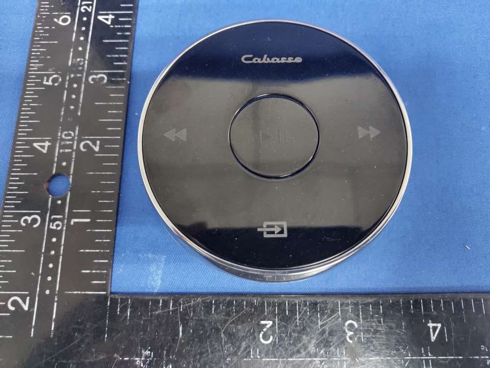
2ACK6-ELC0343
Jun 02, 2021Cabasse Pearl Remote Control
Equipment Class
DTS - Digital Transmission System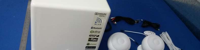
2ACK6STRM3
Jul 20, 2014Active speaker system
Equipment Class
DTS - Digital Transmission System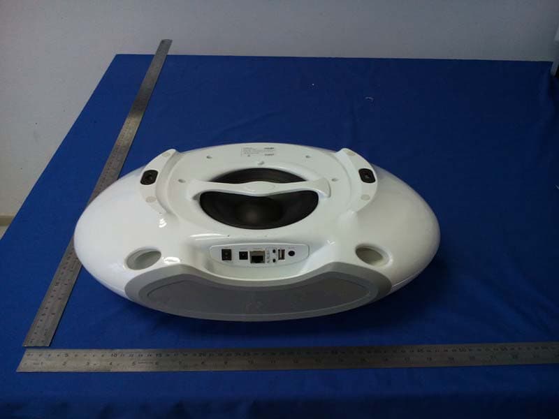
2ACK6STRM1
Jul 03, 2014Active speaker system
Equipment Class
DTS - Digital Transmission System